VPN Technologies
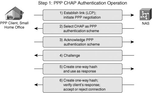
| Although IPsec-based VPNs represent one of the most secure and widely deployed types of VPNs, they are only one of many VPN technologies in existence today. As we'll discuss throughout the course of this book, VPNs have been designed to protect data at almost every layer of the OSI stack. For example, customers in different market verticals will deploy a range of encryption technologies, from Layer 1 bulk encryptors to encryption technologies embedded within the applications themselves (SSL-based VPNs). The OSI model consists of 7 layers, Physical, Data-Link, Network, Transport, Session, Presentation, and Application. Although our primary focus will be IPsec VPNs, which are a Layer 3 VPN technology, it is important to understand IPsec VPNs within the context of other VPN technologies corresponding to different layers within the OSI stack. Figure 1-4 illustrates the OSI stack and provides some examples of VPN technologies that operate at each corresponding OSI layer Figure 1-4. VPN Technologies and the OSI Model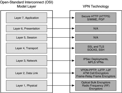 Virtual Private Dialup NetworksVirtual private dialup networks (VPDN) are used to tunnel data across a shared media. Although the primary goal of a VPDN is to tunnel data across shared network infrastructures, some VPDNs may also incorporate data confidentiality. Most VPDNs rely on the use of PPP to encapsulate data in transit across a common network infrastructure. Typical VPDN deployments consist of one or many PPP clients establishing a PPP session that terminates on a device at the opposite end of the tunnel, usually located at a central location within the enterprise or service provider edge. In doing so, a secure point-to-point tunnel is established from the client's network to the PPP concentrator. After the tunnel has been established, the client's network appears as if it were the same network as the enterprise side, while the underlying common network infrastructure across which data is tunneled remains unchanged. Common VPDN technologies deployed in today's networks include Layer 2 Forwarding Protocol, Point-to-Point Tunneling Protocol, and Layer 2 Tunneling Protocol. Layer 2 Forwarding ProtocolThe Layer 2 Forwarding (L2F) Protocol was originally developed by Cisco Systems as a way to tunnel privately addressed IP, AppleTalk, and Novell Internet Protocol Exchange (IPX) over PPP or Serial Line Internet Protocol (SLIP) dialup connections over shared networks. In order to do this, this VPDN technology concentrates tunnels at a home gateway, allowing all dial-up networks to appear as if their physical point of termination is the home gateway itself, regardless of the location of their actual dialup termination point. L2F uses control messages on UDP port 1701 to establish the session. Once a tunnel is established, L2F-encapsulated packets are forwarded in parallel with L2F control datagrams. Both L2F control and payload datagrams are forwarded on UDP 1701. The L2F encapsulated PPP packets have the format described in Figure 1-5. Figure 1-5. L2F Data Packet Format During the creation of an L2F tunnel, initially a user dials into the Network Access Server (NAS), negotiates PPP, and is authenticated with either Password Authentication Protocol (PAP) or Challenge Handshake Authentication Protocol (CHAP), as illustrated in Figure 1-6. Figure 1-6. L2F Topology and Tunnel Establishment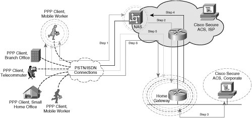 Note In an L2F environment, a "home" gateway refers to a gateway located at the corporate headquarters. The following steps describe the creation of an L2F tunnel, as illustrated in the steps in Figure 1-6:
Point-to-Point Tunneling ProtocolPoint-to-point Tunneling Protocol (PPTP), a technology originally created by Microsoft, provides a seamless integration of remote PPP capable devices into an enterprise network. PPTP leverages authentication parameters inherent to native PPP and the tunneling capabilities of GRE to establish a VPDN. After a client has established a PPTP tunnel to a concentrator on a centralized enterprise network resource, that client appears as if it were part of the enterprise network itself, regardless of the underlying common infrastructure that the data is tunneled across. Consider the following exchange between a small remote office network (the PPP client) and a corporate VPDN (PPTP) concentrator. Figure 1-8 illustrates the order of operations executed when a client accesses the VPDN using PPTP. Figure 1-8. PPTP Topology and Tunnel Negotiation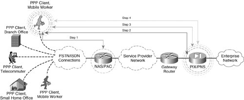 The PPP client in this scenario needs to connect to their enterprise network. The corporation's security policy mandates that data be separated from the common service provider infrastructure and that central network connectivity provided by the service provider must remain transparent to the PPP clients, who are PSTN or ISDN attached. In order to accomplish this task, PPTP is used to provide an end-to-end tunnel for PPP connections inbound to the service provider. Generally, there are two different types of PPTP VPDN tunnels: compulsory tunnels and voluntary tunnels. Compulsory tunnels are formed when a PPP client accesses the NAS or PPTP Access Concentrator (PAC). The NAS/PAC in turn establishes a tunnel with the PPTP Network Server (PNS). Voluntary tunnels are formed when a PPP client directly negotiates a PPTP tunnel with the PNS. The creation of a voluntary PPTP tunnel executes the following steps (illustrated in Figure 1-8):
Note The header used in the PPTP encapsulation process is similar to a GRE header, with some slight modifications to the specification outlined in RFC 1701. The PPTP version of the GRE header includes an acknowledgment field to determine the rate at which packets are traversing the PPTP tunnel. The preceding scenario describes a voluntary PPTP tunnel negotiation between the PPP client, which also acts as its own PAC, and the corporate PIX Firewall, acting as the PNS. In a compulsory PPTP tunnel negotiation, the NAS would act as the PAC and would multiplex multiple sessions from the PPTP clients into a single tunnel to the PIX, or PNS. The exchanges in a compulsory tunnel would follow the same steps chronologically, but would appear as displayed in Figure 1-10. Figure 1-10. A PPTP Compulsory Tunnel Setup between PAC and PNS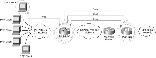 Note Although both L2TP and PPTP support both voluntary and compulsory tunnels, Cisco IOS only supports voluntary and compulsory tunnels for L2TP. While voluntary PPTP tunnels are supported in Cisco IOS, compulsory PPTP tunnels are currently not supported. As depicted in Figure 1-10, only a single tunnel is negotiated between the PAC/PNS pair. In a voluntary exchange, it is possible that all 5 PPP clients dialing into the NAS terminate separate tunnels with the PIX/PNS. As such, compulsory tunnel architectures can be used to keep tunnel termination overhead low on the PNS. In the examples in this chapter, the voluntary tunnel negotiation option could yield up to five times the tunnel maintenance of a compulsory tunnel negotiation option (five PPP clients initiating tunnels to the PIX in a voluntary arrangement vs. one tunnel initiated from the NAS in a compulsory setting). Compulsory tunnels, however, do not offer end-to-end confidentiality with MPPE. In the preceding compulsory arrangement, the PPP connections to the NAS would remain unencryptedonly the connection from the PAC to the PNS would be encrypted with MPPE. As such, those network administrators requiring fully confidential exchange of data in their PPTP environments should choose to allow their clients to voluntarily negotiate an end-to-end PPTP tunnel with the PNS or, in this case, the corporate PIX Firewall. In doing so, the network administrator can ensure that all legs of the VPDN from their remote dialup hosts using PPP to their corporate PNS are encrypted for end-to-end data confidentiality. Layer 2 Tunneling ProtocolLayer 2 Tunneling Protocol (L2TP) is a collaborative effort to develop a standards-based VPDN protocol within IETF. Vendors collaborating on this initiative include, among others, Cisco and Microsoft. As with PPTP, L2TP is a client-server operation consisting of two main components:
A typical L2TP session resembles a compulsory PPTP tunnel negotiation between a PAC and a PNS. As with PPTP, two types of data are forwarded into an L2TP tunnelcontrol data and tunnel data. Unlike PPTP, however, L2TP is not connection oriented. Instead, it is packet oriented. So, whereas PPTP relied on a TCP-based connection to establish a control channel between the PAC and PNS, L2TP uses UDP to maintain control data and tunnel data simultaneously. L2TP leverages the use of control messages and data packets as follows:
Note L2F control and payload packets are also sent on UDP port 1701. Network devices inspect the version field to differentiate between L2F and L2TP packet formats. Figure 1-12 depicts a sample L2TP tunnel setup in which a company uses L2TP to establish seamless, secure connectivity across an untrusted media. In this case, that shared network is the ISP cloud. The ISP owns the access server that terminates the customer's dialup connection using PPP as the Layer 2 protocol. In this example, the access server also serves as the LAC. The LNS is located on the customer premises and terminates the L2TP tunnel originated from the LAC. Figure 1-12. L2TP Tunnel Negotiation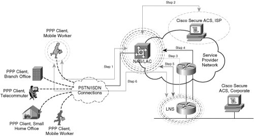 The following steps outline the creation of the L2TP VPDN from the remote host to the corporate network as described in Figure 1-12:
Multiprotocol Label Switching VPNsMultiprotocol Label Switching (MPLS) VPNs logically separate VPN traffic over a shared media through the use of VPN Routing and Forwarding Instances (VRFs). In an MPLS network, different devices play different roles to achieve this logical separation:
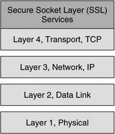
Caution An MPLS VPN does not provide confidentiality unless it is deployed in conjunction with IPsec. A VRF describes a separate routing and forwarding table, enabled by the use of Route Descriptors, which are 8-byte unique identifiers derived from VPN-specific information at the provider edge (PE). MPLS VPNs enable customer edge (CE) routers to establish normal Layer 3 RP adjacencies with MPLS-aware PE routers. Each PE router is MPLS VPN aware and is able to forward traffic to its destination PE router on the opposite side of the provider core using VPNv4 addresses learned from MP-BGP advertisements from other PE routers. The provider core routers remain unaware of the customer network's routing table or IP addressing information. Instead, traffic is switched within the MPLS cloud using labels and an entry in the P router's label forwarding information base (LFIB). Figure 1-13 illustrates IP-routed and VRF-routed domains with MPLS. Figure 1-13. Traffic is IP-Routed to the Provider Edge (PE) When the traffic from the customer edge reaches the PE router, it is then label switched across the MPLS Service Provider core to its destination PE router. In this manner, customer routing and IP addressing information is kept virtual and private from the provider corethe P routers use MPLS labels and an associated LFIB entry to forward the traffic across the MPLS core rather than IP addressing information. When MPLS-switched traffic arrives at the destination PE router, traffic can be forwarded to neighboring CE routers based on the previously installed VPNv4 address learned from MP-BGP advertisements from neighboring MP-BGPenabled PE routers. The CE routers perform IP RIB lookups to determine the appropriate destination and forwarding decisions within the customer core IP network. The operation of MPLS offers separation of multiple virtual data networks across a shared network such as an ISP. The addition of MPLS labels at the service provider core allows customers to separate networks from other customers virtually over a shared core network such as a service provider network. The use of route descriptors on PE nodes provides separation at the control plane, allowing customers to use overlapping address space and overlapping services that would normally present conflict within a non-MPLS environment. As mentioned previously, data-plane separation is achieved using VPN labels to make the forwarding decisions on PE routers. IPsec VPNsIPsec VPNs encrypt data at the Layer 3 IP packet layer, offering a comprehensively secure VPN solution through providing data authentication, anti-replay protection, data confidentiality, and data integrity protection. As such, IPsec is one of the most widespread VPN technologies in today's enterprise, service provider, and government networks. Using ESP in tunnel mode, IPsec supports the rewrite of Type of Service (ToS) bits into an outer IP header, thereby supporting encrypted data payloads while preserving quality of service (QoS) within a given network. IPsec is a standards-based protocol and therefore supports interoperability across products from multiple vendors. Note Although IPsec is standards based, there are many optional components of IPsec (not required for RFC compliance) and proprietary innovations that present compatibility considerations in multi-vendor environments. We will discuss these design considerations in greater detail in Chapter 8, "Handling Vendor Interoperability with High Availability." As we will discuss, IPsec is supported within Cisco IOS on a wide array of different routers, firewalls, VPN Service Modules, VPN concentrators, and VPN clients. Likewise, Cisco offers a variety of different hardware-based VPN acceleration options for enhanced VPN performance within a network. IPsec will serve as the primary VPN discussion point for the duration of this book. IPsec VPNs tunnel data across shared media using ESP, AH, or a combination of both. These two standards-based protocols both use symmetric encryption technology. Note The precise operation of ESP and AH are outlined more comprehensively in Chapter 2. IPsec-supported symmetric encryption transforms include data encryption standard (DES, 56-bit transform), triple data encryption standard (3DES, 168-bit transform), and most recently, advanced encryption standard (AES, 256-bit transform). Security parameters, including keys used for symmetric encryption, are communicated securely using the Internet Key Exchange (IKE) protocol, which is also considered part of the IPsec protocol suite. The operation of protocols incorporated within the IPsec protocol suite is discussed in greater detail in Chapter 2. Subsequent chapters will explore design considerations of IPsec-based VPNs. Transport Layer VPNsTransport layer VPNs provide an additional layer of security at the transport of the OSI stack. Transport layer VPNs typically consist of a client application and a server. A transport layer VPN will undergo a handshake to agree on common parameters to use for the SSL or TLS session, including cryptographic keying material and transforms. The messages in this handshake are confidentially exchanged between client and server, typically with a form of public key encryption such as RSA encryption. During the handshake, the client and server also agree on a set of symmetric session keys and a symmetric key transform, such as DES or 3DES, for bulk data encryption over the SSL VPN. Secure Socket Layer VPNsIn today's network architectures, Secure Socket Layer (SSL) VPNs represent one of the most popular choices for transport layer security. SSL was originally developed by Netscape in 1994 to secure client/server applications across the Internet. SSL is effective at providing data authentication, data integrity, and data confidentiality between client and server applications, but it does not offer data non-repudiation services. As discussed before, SSL is performed over TCP in the transport layer of the OSI stack, as illustrated in Figure 1-14. Figure 1-14. SSL and the OSI Stack SSL follows five broad steps when establishing a secure sessionclient exchange of cryptographic parameters, server exchange of cryptographic parameters, cryptographic key derivation, session authentication, and secure data exchange. Refer to the scenario illustrated in Figure 1-15 for the following description of SSL tunnel negotiation. In the SSL tunnel negotiation, public key encryption is typically used for initial client and server authentication. The client and server also exchange public keys to encrypt each message in the handshake. Once the handshake is completed, symmetric key transforms are used for bulk data encryption between client and server. Figure 1-15. SSL Tunnel Establishment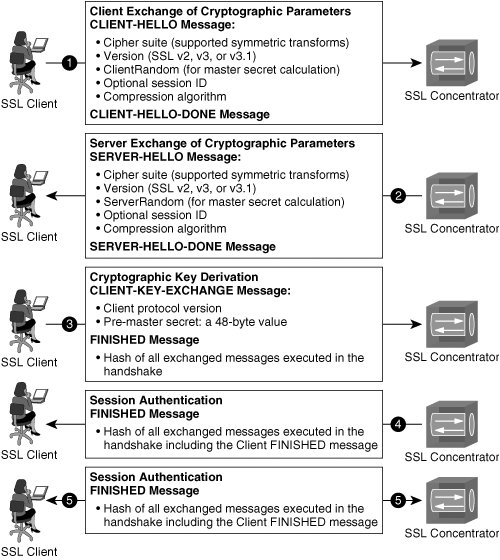 The following order of operations describes the SSL handshake illustrated in Figure 1-15: Note RSA signatures are commonly used to facilitate the authentication and confidential exchange of messages during the SSL handshake. RSA Signatures, including x.509-based certificates and certificate authorities, are discussed in full detail in Chapter 2 and Chapter 12, "Public Key Infrastructures and IPsec."
Note The creation of hashed message authentication codes is covered in greater detail in Chapter 2. Transport Layer Security and SSL VPNsSSL was originally developed by Netscape and has proven to be effective for HTTPS communications. However, the IETF standards track protocol for security at the transport layer is actually transport layer security (TLS). The operation of TLS is similar to SSL 3.0 but has significant modifications, specifically with respect to support for different cryptographic algorithms, that make the two incompatible with one another. TLS has big implications in 802.1x identity-based networking systems, because extensible authentication protocol with TLS (EAP-TLS) is part of the 802.1x standard. Additionally, TLS is a critical component in wireless network security. Although not formally a component of the newly ratified 802.11i IEEE standard for wireless network security, EAP-TLS is the de facto means of authentication in 802.11i-compliant networks. |
EAN: 2147483647
Pages: 113