Lab 3.1: Replacing a Floppy Drive
The 51/4-inch floppy drive was part of the original PC. Most personal computers still have a floppy drive, although these days it is usually a 1.44MB 31/2-inch drive.
Replacing a floppy disk drive in any computer involves opening the case—and that means you may lose the computer’s CMOS disk drive settings. Without its CMOS data, the computer won’t work, so you must be able to replace this data. Therefore, you need to make a record of this data before you begin the process of floppy-drive replacement.
| Note | Remember to practice standard ESD safety anytime you open the case. It’s important! |
Upon completion of this lab, you will be able to:
-
Remove a floppy drive
-
Install a floppy drive
Set Up
For this exercise, you will need a working computer with a floppy drive installed.
Exercises
In this lab, you’ll run a CMOS setup and record the data. Then you’ll work through the steps of removing any expansion cards in your path, removing the floppy drive, and reinstalling the floppy drive.
Removing a Floppy Drive
To remove a floppy drive,
-
Run the CMOS setup routine and record the drive data in the table provided:
Note You can access the CMOS setup routine several different ways, depending on the brand of BIOS. Some of the common ways to start the routine are to press Delete, F2, Ctrl+F1, or Ctrl+Alt+Esc. Most manufacturers tell you how to enter the CMOS setup as the computer is booting.
Drive
Physical Size
Capacity
A:
____________
____________
B:
____________
____________
Drive
Cylinders
Heads
Sectors
C:
____________
____________
____________
D:
____________
____________
____________
-
Boot the computer, place a floppy disk in drive A:, right-click the drive A: icon in the My Computer window, and then click Explore to display the floppy disk’s contents to verify that drive A: is operational.
-
Shut down the computer and turn off the power to all peripherals attached to the computer.
-
Open the computer case.
Warning As soon as the cover is removed, put on your antistatic wrist strap to protect the computer from ESD.
-
If any of the expansion cards are obstructing your access to the floppy drive, you need to remove them. Important: Before you remove any expansion cards, prepare a sketch that shows where each expansion card goes in the motherboard expansion slots and where any cables or wires are connected to the expansion card. On your sketch, note the pin 1 edge (the edge that has a stripe) on the cables and the colors of individual wires attached to the expansion card.
-
Once the sketch has been completed, disconnect any wires and cables connected to the expansion cards that are obstructing your access and remove the cards one at a time. To remove a card, remove the mounting screw, grasp the expansion card with both hands, and pull upward while gently rocking the board from front to back (see Figure 3.1).
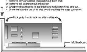
Figure 3.1: Removing an expansion card -
As soon as the expansion card is out, place it on an antistatic mat to protect against ESD.
Note Any expansion cards that are removed must be reinstalled before you replace the computer cover.
-
The power cable plug on the floppy drive is keyed so it fits only one way, but the ribbon (data) cable can be accidentally reversed. To keep this from happening, note the pin 1 position of the floppy drive so you can later match it with the striped edge on the data cable when the drive is reinstalled. After you’ve done this, disconnect the ribbon (data) cable and power cable from the floppy drive. Note the pin 1 position to the controller on the motherboard and remove the floppy cable from the controller.
-
To remove the floppy drive from the computer, unbolt or release the floppy drive from the drive bay and pull the drive out of the front of the computer. You may have to remove the front panel to do this.
Installing a Floppy Drive
To install a floppy drive,
-
Slide the drive into the drive bay and fasten it in.
-
Attach the DC power connector to the drive.
-
Attach the ribbon (data) cable to the drive, with the striped edge of the ribbon cable on pin 1 of the floppy-drive plug. If this is the only floppy drive in the computer, it is drive A: and must be attached to a connector that is between the twisted wires and the end of the cable. If this is a second floppy drive, it is drive B:. Drive B: must be attached between the twist in the floppy- drive cable and the floppy-drive controller. (See Figure 3.2.)
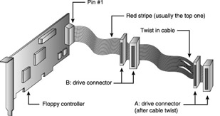
Figure 3.2: A typical floppy cable -
Attach the ribbon cable to the controller with the striped edge on the cable connected to pin 1 on the controller.
-
Using the sketch you made, reinstall all expansion cards that you removed. To install an expansion card, place the card in the same motherboard slot from which you removed it and press down firmly until the card is seated in the slot. Reconnect any cables or wires you disconnected from the card, and then replace the expansion card screw.
-
Replace the computer cover and connect all external cables.
-
Run the CMOS setup sequence. If the floppy drive indicated in the CMOS is incorrect for the new drive, select the type of drive you installed. When you exit CMOS setup, the computer will reboot, and the new settings will be loaded.
-
Boot the computer, place a floppy disk in drive A:, right-click the drive A: icon in the My Computer window, and then click Explore to display the floppy disk’s contents to verify that drive A: is operational
-
If drive A: isn’t working, check whether the floppy-drive light is always on. A floppy-drive light that is constantly on usually indicates that the data cable is upside down.