Foundation and Supplemental Topics
Cisco IPS Response OverviewBeginning with Cisco IPS version 5.0, your signature response options increased because of the inline response options. Now when you configure your signatures, you can choose one or more of the following responses for a triggered signature:
Note The Modify Packet Inline action was added to support the Normalizer signature engine. For more information on using the Normalizer signature engine, refer to Chapter 6, "Cisco IPS Signature Engines." The standard response to a triggered signature is the generation of an alert (alarm). This chapter focuses on other actions that your IPS signatures can invoke. Inline ActionsBy adding inline functionality, Cisco IPS was able to incorporate the following signature actions:
These actions impact even the initial traffic from an attacking system. Therefore, they can be used to prevent attack traffic from reaching the target system or network. To use these actions, however, you must configure your sensor using inline mode. Deny Packet InlineConfiguring a signature with the Deny Packet Inline action causes your sensor to drop any packets that match the signature's parameters. This action is useful for preventing specific attack traffic while allowing all other traffic to continue to travel through the network. Deny Connection InlineIn some situations, you need to deny all of the traffic for an entire connection (not just the initial attack traffic). Configuring a signature with the Deny Connection Inline action causes the sensor to drop all traffic for the connection that triggered the signature. A connection is defined as all traffic in which the following fields match the traffic that triggered the signature:
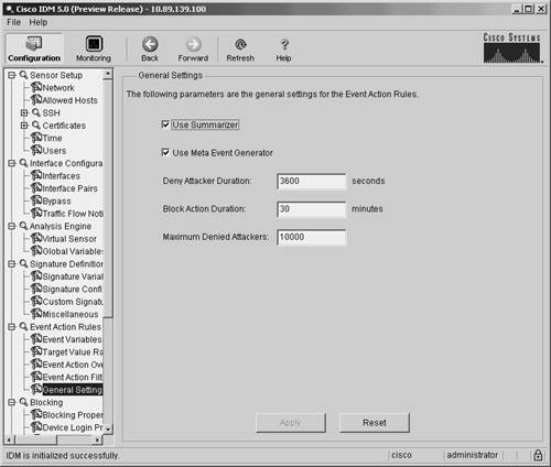
The traffic for the connection is denied for the length of time specified by the Deny Attacker Duration parameter. After the configured amount of time has passed, the traffic matching the connection's parameters is no longer denied. Deny Attacker InlineConfiguring a signature with the Deny Attacker Inline action causes the sensor to drop all packets from the attacker's IP address. This action prevents the entry of all traffic originating from the attacker's IP address, not just traffic that matches the initial connection that triggered the signature. Again, the Deny Attacker Duration parameter determines for how long the traffic from the attacker's IP address is denied. Configuring Deny Attacker Duration ParameterWhen using inline actions, you need to define the length of time that the sensor continues to deny the traffic. This length of time (measured in seconds) is defined by the Deny Attacker Duration parameter. You can also configure the maximum number of attackers that the sensor will deny at one time by using the Maximum Denied Attackers field. To configure both of these parameters, perform the following steps:
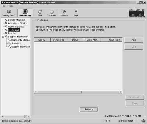
Logging ActionsIP logging enables you to capture the actual packets that an attacking host is sending to your network. These packets are stored on the sensor, either on the hard drive or in memory (for sensors without hard drives). You can then analyze these packets by using a packet analysis tool, such as Ethereal, to determine exactly what an attacker is doing. You can capture traffic by using IP logging in response to both a signature configured with the IP logging action as well as a manually initiated IP logging request. When logging an attacker's activity, you have the following three options:
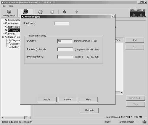
Note The length of time that the sensor logs traffic after a signature is triggered depends on the values of the IP Log parameters. For information on how to configure these parameters, refer to Chapter 8, "Sensor Tuning." Log Attacker PacketsConfiguring a signature to use the Log Attacker Packets action causes the sensor to log (or capture) traffic from the source IP address that caused the signature to trigger. This will show you all the systems and services that the attacking system is accessing. Log Pair PacketsInstead of logging all the traffic from the source IP address of the traffic that triggers a signature, you can limit the number of packets logged by configuring a signature for the Log Pair Packets action. This action causes a signature to log only the traffic that matches both the source and destination IP addresses that initially triggered the signature. Log Victim PacketsThe third logging option is Log Victim Packets. This action causes the sensor to log all the packets going to the victim (destination) IP address. This option is useful for monitoring the target system in situations where the attack may be coming from multiple IP addresses. By logging traffic to the target system, you can identify all the traffic going to the victim machine. Manual IP LoggingSometimes you may want to capture the traffic from a specific source address. When initiating manual logging, you can specify the amount of traffic to capture by using one of the following characteristics:
To manually initiate IP logging using IDM, perform the following steps:
IP BlockingIP blocking enables you to halt future traffic from an attacking host for a specified period of time, thereby limiting the attacker's access to your network. You have the following two options with respect to IP blocking:
The Request Block Host action causes the sensor to block all traffic from the host that triggered the signature. This is very effective at protecting your network because all the traffic from the attacking system is prevented from entering your network. The drawback is that if the alarm is a false positive, you will cause a denial of service (DoS) attack until you have time to analyze the situation and remove the block (or until it expires automatically). The same situation applies if the attacker is able to spoof the source address in the attack traffic, such as with User Datagram Protocol (UDP) traffic since it is connectionless. In that case, the attack traffic can be used to arbitrarily block access to various systems by spoofing their IP addresses. The Request Block Connection action, however, blocks only traffic (from the host that triggered the signature) to the destination port of the traffic that triggered the signature. If an attacker targets a specific service on systems across your network, Request Block Connection would prevent the attack from proceeding. The attacker would still be able to send traffic to other services or ports (any destination port except the destination port that originally triggered the alarm). In a false positive situation, you deny only a single service (port number) on the normal user's system. This is still a DoS situation but is not as severe as denying all traffic from the user. You configure IP blocking on an individual-signature basis. This section focuses on explaining the following topics:
Before broaching these topics, you may benefit from reviewing some of the terminology used in conjunction with IP blocking. IP Blocking DefinitionsTable 9-2 lists the terms commonly used in conjunction with IP blocking.
IP Blocking DevicesYou can configure your sensor to perform device management on a variety of Cisco devices. You can use the following types of devices as managed devices:
Cisco RoutersThe following Cisco routers have been tested and approved to serve as blocking devices:
The Network Access Controller (NAC) on a single sensor can control up to ten interfaces on any of the supported devices. When using IP blocking, your sensor must be able to communicate with the managed device in order to reconfigure the device to block the traffic from the attacking system. Your sensor logs in to the managed device and dynamically applies an ACL. The sensor also removes the block after a configured amount of time. To manipulate the ACLs on the managed device, configure the following on your managed routers:
Note Although Telnet is available, SSH access to your IOS router is preferred because the communication with the router is encrypted (preventing someone on the network from sniffing your login credentials). Cisco Catalyst 6000 SwitchesSome Catalyst 6000 switches do not support ACLs (for example, those without an MSFC). You can still use these devices to perform device management by using VLAN Access Control Lists (VACLs) if you have a Policy Feature Card (PFC) and you are running CatOS. Note To support ACLs on your Catalyst 6000 switch, you must have an MSFC installed on the switch. If your supervisor module contains a PFC, your Catalyst 6000 switch supports VACLs. If you have neither a PFC nor an MSFC, your Catalyst 6000 switch supports neither VACLs nor ACLs, and it cannot be used for IP blocking. To manipulate the VACLs on the Catalyst 6000 switch device, you must configure the following on your Catalyst switch:
Note If your Catalyst 6000 switch has an MSFC and you are running CatOS on your switch, you have the option of using ACLs or VACLs when implementing IP blocking. Note Although Telnet is available, SSH access to your Catalyst 6000 switch is preferred because the communication with the switch is encrypted (preventing someone on the network from sniffing your login credentials). Cisco PIX FirewallsIn addition to Cisco routers and Catalyst 6000 switches, you can also use Cisco PIX Firewalls (and ASAs) to serve as managed devices. Instead of updating an ACL on the router, however, the sensor uses the PIX Firewall's shun command to block the traffic from the attacking system. Since the shun command was introduced in version 6.0 of the PIX operating system, any of the following PIX models running version 6.0 or higher can serve as a managed device:
Just as with the Cisco routers that serve as blocking devices, your sensor must be able to communicate with the PIX Firewalls being used as blocking devices. To communicate with the PIX Firewall, you must enable one of the following communication protocols:
Note Although Telnet is available, SSH access to your PIX Firewall is preferred because the communication with the firewall is encrypted (preventing someone on the network from sniffing your login credentials). This is especially important for access to your PIX Firewall because it is installed to protect your network. No matter which of these communication protocols you decide to use, you must assign an enable password to your PIX Firewall. Blocking GuidelinesThe IP blocking functionality in Cisco IPS provides a powerful tool to protect your network. If IP blocking is used incorrectly, however, a knowledgeable attacker can use the error against your network in a DoS attack. The IP blocking feature generates ACLs that are based solely on IP addresses. The sensor has no mechanism to determine whether the address being blocked is a critical server on your network or the address of a legitimate attacker. Therefore, implementing IP blocking requires careful planning and analysis. Some of the important considerations in designing and implementing IP blocking are as follows:
Antispoofing MechanismsAttackers will usually forge packets with IP addresses that are either private addresses (refer to RFC 1918) or addresses of your internal network. The attacker's goal is to have Cisco Secure IPS block valid IP addresses, thus causing a DoS. When you properly implement an antispoofing mechanism, Cisco Secure IPS will not block these valid addresses. An excellent reference on IP address filtering is RFC 2827, "Network Ingress Filtering: Defeating Denial of Service Attacks Which Employ IP Source Address Spoofing." This reference explains how you can apply basic filtering to your router interfaces. Although these recommendations are not foolproof, they significantly help reduce the IP spoofing attacks against your network. Basically, you want to make sure that all of the traffic leaving your protected network comes from a source IP address that is a valid address on your protected network. Consequently, for traffic entering your protected network, you need to make sure that the source IP address is not one of your valid internal addresses. Addresses that violate these criteria are probably spoofed and need to be dropped by your router. Critical HostsMany hosts on your network perform critical tasks. To prevent any possible disruption of the operation of your network, these systems should not be blocked. Critical components that should not be blocked include the following:
By establishing never-block addresses (see "Defining Addresses Never to Block" later in the chapter) for these critical systems, you can prevent IP blocking from disrupting the operation of these important systems (either accidentally or during a deliberate attack). Network TopologyYour network topology impacts the implementation of IP blocking. You will have sensors deployed throughout your network, but a single blocking device can be controlled by only one sensor. You need to decide which sensors will control which managed devices. Furthermore, a single sensor can perform IP blocking only on a maximum of ten interfaces across one or more managed devices. Entry PointsMany networks have multiple entry points to provide redundancy and reliability. These entry points provide multiple avenues for an attacker to access your network. You need to decide if all of these entry points need to participate in IP blocking. Furthermore, you need to make sure that when IP blocking is initiated on one entry point, an attacker cannot bypass the block by using another entry point. If multiple sensors perform blocking on your network, you will need to configure Master Blocking Sensors to coordinate blocking between these various sensors. Signature SelectionCisco IPS supports hundreds of signatures. It is not feasible or manageable to perform IP blocking on all of these signatures. Some signatures are more susceptible to spoofing than others. If you implement IP blocking on a UDP signature, for instance, an attacker may be able to impersonate one of your business partners, causing you to generate a DoS attack against your own network. Other signatures are prone to false positives. Implementing IP blocking on these signatures can disrupt normal user traffic since the sensor has no way of distinguishing a false positive from a real attack. Deciding which signatures you want to perform IP blocking and whether the blocking will be for the destination port only (Request Block Connection) or all traffic (Request Block Host) is one of the major configuration tasks in implementing IP blocking on your network. Blocking DurationThe default blocking duration is 30 minutes for signatures configured to perform IP blocking. You need to decide whether this value is appropriate for your network environment. IP blocking is designed to stop traffic from an attacking host to enable you to analyze what is happening and give you time to take more long-term blocking actions, if appropriate. Note For manually initiated IP blocking, the default duration is 60 minutes. If your blocking duration is too short, the attacker will regain access to your network before you have had a chance to fully examine the extent of the attack and to take appropriate actions. If the initial attack compromises a system, the subsequent access (after the blocking duration expires) might appear to be normal user traffic and might not trigger any of your IPS signatures. So it is important to thoroughly analyze the attack before the attacker can regain access to your network. Setting your blocking duration too high, however, also has its drawbacks. A very large duration value creates a DoS situation when the block occurs because of a false positive. Since the block duration is long, it will impact the normal user for a longer period of time (usually until you have analyzed the circumstances and determined that the alarm was a false positive). You must carefully consider the appropriate blocking duration for your network environment. Device Login InformationWhen implementing IP blocking, your sensor must be able to log in to the managed device and dynamically apply an ACL (or other IP blocking feature). Therefore, your sensor needs to have privileged login credentials to this device. Some devices support SSH, whereas others may support only Telnet. When you connect via Telnet, the connection needs to traverse a secure network (to protect login credentials), whereas SSH access has somewhat more flexibility because the traffic is encrypted. Interface ACL RequirementsAn interface/direction on your managed device can have only one ACL applied to it. If you already have existing ACL entries on a given interface/direction (besides the block entries generated by the NAC), you need to configure these entries in either a Pre-Block ACL or Post-Block ACL (or both) on your managed device. When the NAC generates a blocking ACL for a device, it first includes all of the entries from the Pre-Block ACL. Then it adds the block entries that it dynamically creates. Finally, it adds the entries from the Post-Block ACL. This is the complete ACL that is applied to the managed device. Blocking ProcessBlocking is initiated when a signature configured for IP blocking triggers an alarm or when a manual blocking event is generated. This causes the NAC to create the appropriate blocking ACLs (or sets of configurations) and to send this information to all of the managed devices that it controls. At the same time, an alarm is sent to the Event Store. When the block duration expires, the NAC updates the ACLs (or configurations) to remove the block from each controlled device. The NAC is the sensor service that controls starting and stopping blocks on routers, switches, and PIX Firewalls (and ASAs). A block is initiated when one of the following two events occurs:
Note Usually, blocks expire after a configured amount of time. You can also configure the NAC to initiate a permanent block that does not expire until you remove it. These permanent blocks will initiate a persistent connection with your managed device until you remove the block. The blocking process involves the following sequence of operations:
ACL Placement ConsiderationsWhen applying ACLs on your network, consider your operational requirements and network topology. You have several options when applying ACLs to one of your network devices. The ACL might be applied on either the external or internal interface of the router. It can also be configured for inbound or outbound traffic on each of these two interfaces (when using ACLs). Although you can choose inbound or outbound traffic (with respect to the router interface, not your network) on each physical interface, the most ACL placements are illustrated in Figure 9-4. Figure 9-4. ACL Placement When deciding where to apply your ACLs, you need to understand the various options available to you. These options are as follows:
Note VACLs do not have a concept of traffic direction. If you use VACLs, you must limit traffic without regard to the traffic's direction. The traffic direction option specifies whether the ACL is applied to traffic entering the interface or to traffic leaving the interface. You can allow certain traffic into an interface while denying this same traffic from leaving the interface. You must apply a traffic direction when creating an ACL for a given interface on your network. The external interface is located on the unprotected side of your network device (see Figure 9-4). Applying your ACL to your external interface for inbound traffic provides the best protection since the traffic is denied before it enters the router. The internal interface resides on the protected side of your network device (see Figure 9-4). Applying your ACL to your internal interface for inbound traffic does not block traffic from reaching the router itself and prevents you from accidentally blocking traffic that your router needs. External Versus InternalApplying the ACL to the external interface in the inward direction denies a host access before the router processes the packets. If the attacker is generating a large amount of traffic (common for DoS attacks), this reduces the performance impact on your router. Applying the ACL to the internal interface in the outbound direction denies traffic from a host to the devices on your protected network but allows the packets to be processed by the router. This scenario is less desirable, but it has the benefit of preventing you from accidentally denying traffic that the router needs, such as routing updates. Each network configuration has its own requirements. You must decide, based on your unique network architecture, which configuration meets your needs for security and user functionality. ACLs Versus VACLsIn most situations, you are limited to using either ACLs or VACLs. But if you have an MSFC and a Catalyst 6000 running CatOS, you can choose to use either VACLs or ACLs. Therefore, it is helpful to understand the benefits of each of these access-control mechanisms. VACLs are directionless. You can't specify a direction as you can when defining ACLs. This means that if direction is important to you when blocking the traffic, using an ACL is the only choice. ACLs are applied to the MSFC on the switch. The MSFC is essentially a headless router, and any ACLs that you define on the MSFC are used to restrict only the flow of traffic between different VLANs or broadcast domains. ACLs can't be used to restrict traffic between systems on the same network segment (since the traffic is transmitted at the link layer). A VACL, however, is applied at the link layer on the switch (which is one of the reasons why VACLs are directionless). This means that VACLs can restrict traffic between systems that are on the same network segment or VLAN. Using Existing ACLsIn some situations, you may need to configure an IP block on an interface/direction on which you already have an ACL. If you simply configure your sensor to generate blocks for an interface/ direction on the managed device, your existing ACL entries will be lost because the blocking sensor will take control of the interface and apply its own ACL. Therefore, to use blocking on an interface/ direction that has an existing ACL, you need to define the following extra ACLs:
When you configure a sensor as a blocking sensor, it takes control of the ACL for the specified interface and traffic direction on the managed device. If you configure either a Pre-Block or Post-Block ACL, the sensor applies these entries to the managed device by creating a single ACL composed of the Pre-Block and Post-Block entries. When a blocking event occurs, the NAC creates a new single ACL to perform the blocking. This ACL begins with the Pre-Block ACL entries following by the dynamically created block entries and ending with the Post-Block entries. Note Consider carefully which entries you place in your Pre-Block ACL. The addresses allowed by the Pre-Block ACL will come before the dynamically created block entries (in the ACL that is applied to the managed device). That means that these entries can't be blocked by the block entries because the router looks for only the first match in the ACL. Master Blocking SensorDepending on your network configuration, you may have multiple entry points into your network. When one of your sensors initiates a blocking event, it prevents further intrusive traffic from entering your network from that source address. If more than one of your sensors is configured for IP blocking, you probably need these sensors to coordinate their blocking actions with each other so that all entry points into you network are blocked when an attack is noticed by any of your sensors. A Master Blocking Sensor can handle this coordination. It is, perhaps, easiest to explain the Master Blocking Sensor through an example. Figure 9-5 illustrates a scenario in which a network is connected to the Internet through multiple Internet service providers (ISPs). A Cisco Secure IPS sensor monitors each of the entry points into this network. Furthermore, each of the sensors is configured to perform device management on its associated border or perimeter router. Figure 9-5. Master Blocking Sensor Scenario An attacker attempts to compromise a host on the protected network (Step 1 in Figure 9-5). This usually involves the attacker launching an exploit against the target machine. When Sensor A detects the attack, it fires one of the signatures in its database (Step 2 in Figure 9-5). Because the signature is configured for blocking, Sensor A telnets (or uses SSH) into Router A and updates the ACL to block the traffic from the attacker's host. At the same time, the sensor performs other signature actions such as generating the alert event (Step 3 in Figure 9-5). The ACL on Router A will prevent the attacker from sending any traffic into the network through Provider X's network (see Figure 9-5). Because there are two entry points into the network, however, the attacker can reroute his traffic through Provider Y's network because it is still allowing traffic from the attacker's host. Therefore, to completely protect the network from the attacker, Sensor B is configured as a Master Blocking Sensor. After blocking the attacker's traffic at Router A, Sensor A then tells Sensor B to also block the attacker's traffic. Since Sensor B is configured as the Master Blocking Sensor (for Sensor A), Sensor B accepts Sensor A's request and telnets (or uses SSH) into Router B to update the ACL to also block the attacker's traffic. At this point, both entry points into the network are now protected from the attacker. Note A savvy network security administrator will configure Sensor A to command Sensor B to block traffic from Provider Y's router. This will protect the network from attacks initiated through Provider X's network. Then to complete the security configuration, the administrator also needs to configure Sensor A as the Master Blocking Sensor for Sensor B. Therefore, whether an attack comes from Provider X or Provider Y's network, both entry points are protected. Configuring IP BlockingWhen configuring IP blocking, you need to perform numerous configuration operations. These operations fall into the following categories:
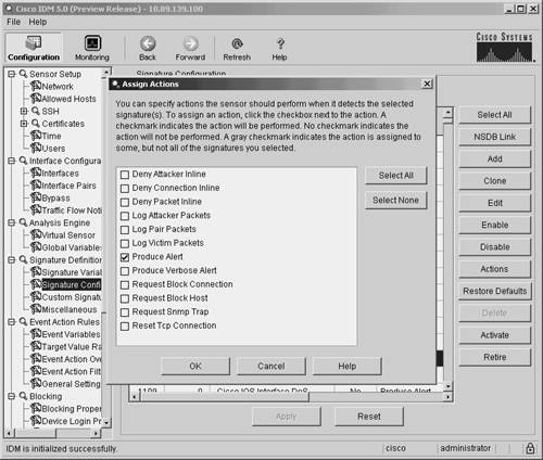
Assigning a Blocking ActionBefore your sensor will initiate IP blocking, configure one or more of your Cisco IPS signatures with a blocking action. In IDM version 5.0, you can configure the actions for a signature by performing the following steps:
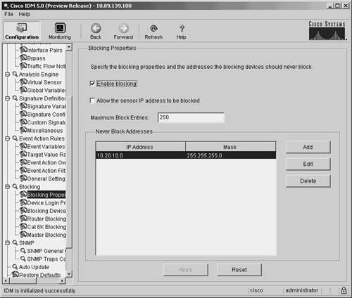
Note You can also configure the actions for a signature by editing the Event Action field for the signature. Configuring signatures is explained in detail in Chapter 5, "Basic Cisco IPS Signature Configuration," and Chapter 7, "Advanced Signature Configuration." Setting Blocking PropertiesCertain blocking properties apply to all of the signatures that are configured with the block action. The following blocking parameters apply to all automatic blocks that the NAC initiates:
The maximum block entries parameter specifies the maximum number of dynamically created block entries that the blocking sensor can place into the ACL to block attacking hosts. This value prevents the sensor from generating an ACL that contains an abnormally large number of entries, which could impact the performance of the managed device. The default value is 250 entries. The blocking properties screen contains a check box that is labeled with something similar to "Allow the sensor IP address to be blocked" (phrasing varies slightly between management systems). Checking this box causes the sensor to place a permit entry for the sensor's IP address at the beginning of the dynamically created block entries. Because this permit statement is processed before any deny entries, traffic to the sensor's IP address can't be blocked by the blocking ACL. The block action duration parameter specifies the length of time that your blocking sensor will wait before removing the blocking ACL. The default block duration is 30 minutes. Unlike the other two general blocking properties, the block action duration parameter is located on the Event Action Rules>General Settings configuration screen. Setting Blocking Properties via IDMTo set the blocking properties through IDM, perform the following steps:
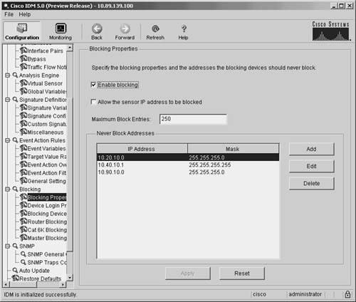
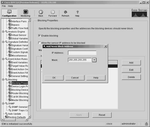
Defining Addresses Never to BlockTo prevent your blocking sensor from blocking traffic to critical systems on your network (either accidentally or because of a deliberate attack), you can configure which IP addresses your blocking device should never block. Note The never-block entries are added (as permit statements) before the dynamically created blocking entries that are generated by the sensor. Since these entries come before any blocking entries, these addresses can't be blocked by the blocking ACL. To configure which addresses can't be blocked by the blocking ACL generated by your blocking sensor when using IDM, perform the following steps:
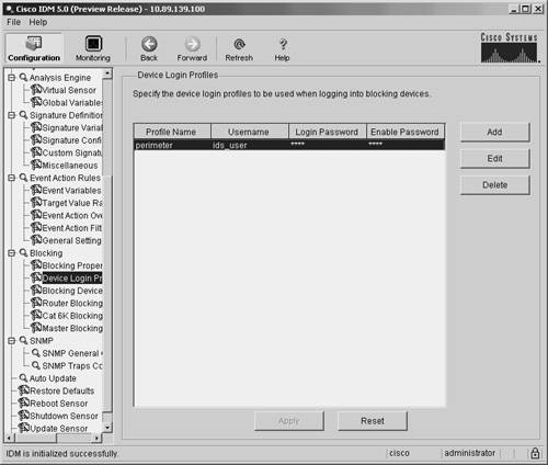
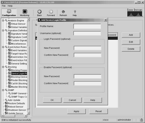
Note From the Never Block Addresses screen, you can manipulate existing entries by highlighting the entry that you want to modify and then clicking on either Edit or Delete. Setting Up Logical DevicesIf you use IDM to manage your sensors, you can configure Device Login Profiles to identify the following authentication parameters for a blocking device:
When you create a blocking device, you associate the appropriate login profile with it. A single login profile can be associated with multiple blocking devices. To configure a device login profile in IDM, perform the following steps:
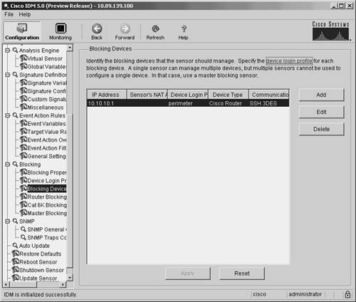
Defining Blocking DevicesCisco IPS supports the following three types of blocking devices:
Each of these blocking devices uses a slightly different mechanism to block traffic on the network. The routers use ACLs to restrict traffic flow. The Catalyst switch uses VACLs to restrict traffic, and the PIX Firewalls use the shun command to restrict traffic. Therefore, the processes for configuring each of these types of blocking devices differ slightly. Note It is important to choose the correct device type when defining a blocking device. The sensor creates the commands to initiate blocking based on this device type. Using the wrong device type (especially with respect to the operating system running on the Catalyst switch) will prevent blocking from operating correctly. Defining Blocking Devices Using IDMWhen you use IDM, defining a blocking device is a two-step process. You must first define the blocking device. Then you define one of the following interfaces that you associate with the blocking device:
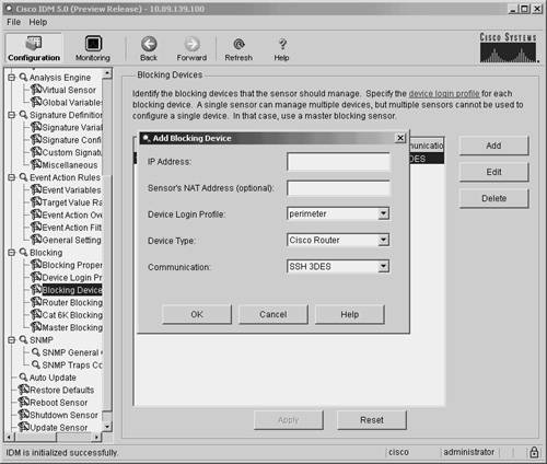
Note You do not need to create an interface when you are using a PIX Firewall as your blocking device. The PIX Firewall performs the blocking via its shun command, so you do not need to specify an interface. So with PIX-managed devices, you need to define only the blocking device itself. You define blocking devices through IDM by defining the fields shown in Table 9-3.
Note If you choose SSH DES or SSH 3DES, you need to use the CLI command ssh host-key to add the router to the list of valid SSH servers before the sensor will be able to successfully communicate with your blocking device. For more information on adding a host key, refer to the section titled "Adding a Known SSH Host" in Chapter 2. To add a blocking device by using the IDM interface, you perform the following steps:
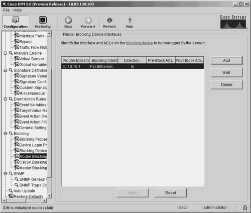
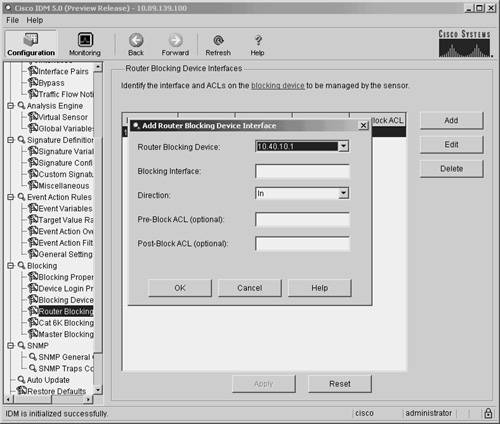
Defining Router Blocking Devices Interfaces Using IDMYour blocking sensor needs to know which interface on your router you want to apply the blocking ACL to. You configure this information by defining a router-blocking device interface entry using the fields listed in Table 9-4.
To add a router interface in the IDM interface, perform the following steps:
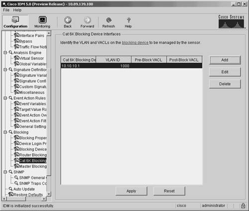
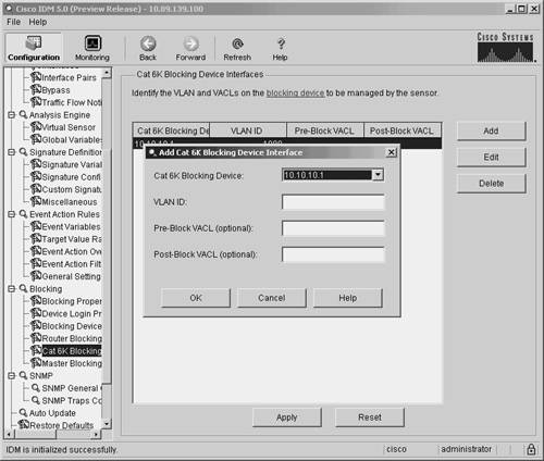
Defining Cat6K Blocking Device Interfaces Using IDMYour blocking sensor needs to know which VLAN on your Catalyst 6000 switch you want to apply the blocking VACL to, along with your Pre-Block and Post-Block information. You configure this information by defining the fields listed in Table 9-5.
To add a Cat6K blocking interface by using the IDM interface, perform the following steps:
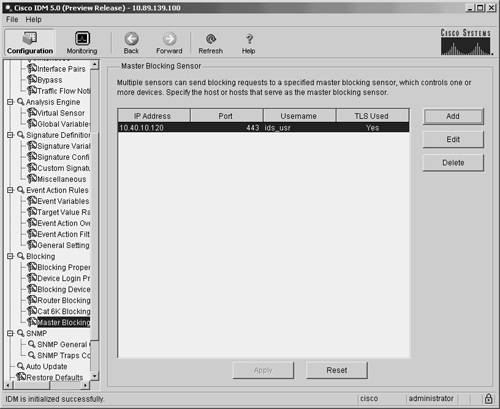
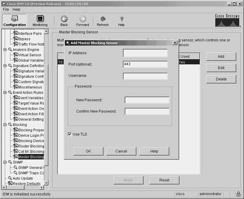
Defining Master Blocking SensorsOne sensor can initiate blocking on multiple managed devices on your network. Only one sensor, however, can initiate blocking on a specific managed device. If you use multiple sensors to perform IP blocking on your network, you will need to define Master Blocking Sensors to coordinate your blocking so that all entrances into your network are protected. Configuring a Master Blocking Sensor in IDMWhen defining a Master Blocking Sensor in IDM, you need to specify the parameters listed in Table 9-6.
Note As when you use SSH instead of Telnet, you should use Transport Layer Security (TLS) when communicating with the Master Blocking Sensor since it encrypts the communication session, preventing an attacker from viewing the information (such as login credentials) exchanged during the session. To add a Master Blocking Sensor in IDM, you need to perform the following steps:
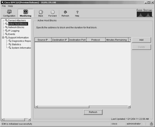
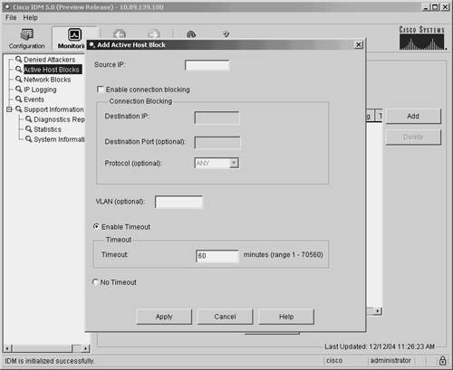
Manual BlockingUsing IDM, you can also manually initiate block requests. You have the option of initiating manual blocks for a single host or for a specific network. Blocking HostsWhen defining a manual block against a single host, you need to define the fields shown in Table 9-7.
To initiate a manual host block, perform the following steps:
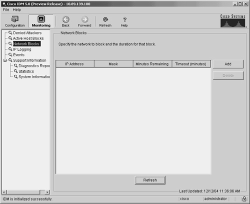
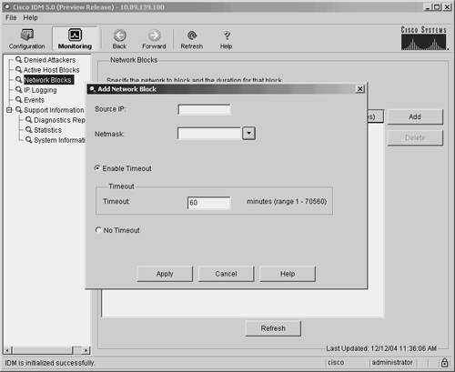
Note You can remove current manual host blocks by clicking on the host block entry to highlight it and then by clicking on Delete. Blocking NetworksWhen defining a manual block against a network, you need to define the fields shown in Table 9-8.
To initiate a manual network block, perform the following steps:
Note You can remove the current manual network block entry by first selecting the network block entry and then clicking on Delete. TCP ResetThe TCP reset response action essentially kills the current TCP connection from the attacker by sending a TCP reset packet to both systems involved in the TCP connection. This response is effective only for TCP-based connections. UDP traffic, for example, is unaffected by TCP resets. Note Transmission Control Protocol (TCP) provides a connection-oriented communication mechanism. The connection is established through a three-way handshake. To terminate a connection, each side of the connection can send a FIN packet, signaling the end of the connection. It is also possible, however, for one side of the connection to abruptly terminate the connection by sending a reset packet (a packet with the RST flag set) to the other side. The sensor uses this approach to terminate an attacker TCP connection. For a detailed explanation of TCP/IP protocols, refer to W. Richard Stevens's book, TCP/IP Illustrated, Volume 1: The Protocols, published by Addison-Wesley. To configure a (TCP-based) signature to perform the TCP reset response action, you only need to configure the Reset TCP Connection action for the signature. Then, when a specific TCP connection triggers the signature, the sensor will send TCP resets to both ends of the connection to terminate it. Although this ends the attacker's connection with your network, it does not prevent the attacker from initiating another connection with your network. This new connection will work until another triggered signature either resets the connection or initiates a blocking response. |
EAN: 2147483647
Pages: 119