Operating and Supporting an MSPP Network
| Operation is the day-to-day task to support a MSPP network. This can include the following actions:
Monitoring Alarms and ConditionsMonitoring alarms and conditions is most easily accomplished using CTC, but you can also use a serial connection to the shelf and TL1 language. In addition, the ONS 15454 shelf has three colored LEDs (yellow, orange, and red) on the front of the shelf fan tray that illuminate for each respective alarm severity: yellow for minor, orange for major, and red for critical. Using CTC permits the user to view alarms and conditions from Shelf view as well as Network view. In each case, the alarms or conditions are related to the respective view. AlarmsFor alarms, if the user is viewing in Network view of CTC and any alarms are present, the alarm information is displayed under the Alarms tab in the bottom half of the CTC display. The affected nodes in Network view of the display also change from green to either yellow for minor alarm, orange for major alarm, or red for critical alarm. If the user is viewing in Shelf view and any alarms are present, the alarm information is displayed under the Alarms tab in the bottom half of the CTC display. The alarm has a description and the severity is displayed in the same colors as mentioned previously. If the alarm is associated with an interface module in the shelf, the module is also colored appropriately for the severity of the alarm. ConditionsFor conditions, if the user is viewing in either Network view or Shelf view of CTC and any conditions are present, there likely would be no visible indication. To view the conditions, the user clicks the Conditions tab in the bottom half of the display to display the conditions table, and then clicks the Retrieve button to display all the conditions related to the shelf. Note Conditions often reflect a "hidden" problem; if ignored, the condition can result in an alarm. Initially, this is a minor alarm; if it is still ignored, it can escalate to a major or critical alarm. Adding or Removing Interface ModulesAfter a ONS 15454 system has been in operation, the time will come when a interface module needs to be added or replaced. Typically, interface modules are added when the system needs to expand. Adding more DS-1 or DS-3 interface modules for anticipated or immediate growth is an example of the need to add interface modules. When an interface module fails or has some technical issue that will create an alarm, it must be replaced. Various types of interface modules exist; replacing one requires following a specific procedure. Procedures for adding or replacing interface modules of various types, and for various reasons, can be found in the Procedure Guide, located at http://www.cisco.com/en/US/products/hw/optical/ps2006/tsd_products_support_series_home.html. Provisioning ServiceProvisioning services is part of the operation of the MSPP. Services exist in the form of the types of circuits required to support various applications, as well as the associated interface module or port the circuits will terminate on. These types of service circuits could be as follows:
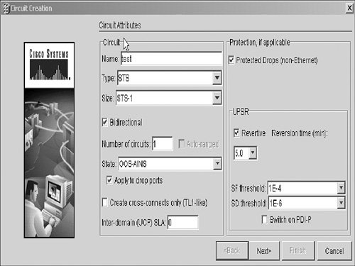
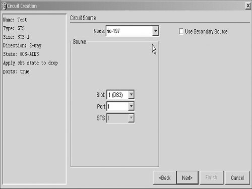
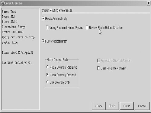
In addition to creating circuits, the user must provision the particular interface module or port on a module being used for the service. The user logs into the ONS 15454 shelf using CTC and is shown Shelf view of CTC. The user selects a particular interface module by double-clicking the graphical representation of the module in the shelf. This presents the module level of CTC and a graphical representation of the module and all interface ports associated with this particular module. (Interface ports can be from 1 to 56, depending on the module.) If the user clicks the Provisioning tab in the lower section of the CTC display, a table (similar to a Microsoft Excel table) displays. Each column in the table has a heading for each parameter associated with the ports of the displayed module. The most commonly used heading is "Service State" or "State." This is the column that the user selects to provision a port to a particular status. Examples of service state are Out of Service (OOS), In Service (IS), In Service Normal (IS-NR), and Out of ServiceMaintenance (OOS-MT). Creating CircuitsProvisioning service is a two-part process: provisioning the interface module or the port of an interface module, and creating a single circuit or multiple circuits. In this section, you will learn about creating circuits to provision services. You can create circuits at the Shelf or Network view of CTC. For this chapter, we use Network view and create a DS-3 circuit from a DS-3 port on a DS-3 interface module in one location (source) to another DS-3 port on a different DS-3 interface module at a second location (destination). CTC allows two methods of creating circuits: manually routing circuits and automatically routing circuits. (Both methods are discussed in this chapter.) Both methods use the Circuit Wizard in CTC. The Circuit Wizard creates a circuit or multiple circuits from one location (called the source) to a different location (called the destination). This is accomplished when the user selects items from drop-down menus, checks boxes, and clicks icons and Next or Finish buttons. Note Source and destination are relative terms, meaning that they don't necessarily have to be two different locations or ONS 15454 shelves. For example, a DS-3 circuit is created from one port of a DS-3 interface module (source) to a different port on the same DS-3 interface module (destination), which is typically called a "hairpin circuit." Source and destination just refer to the two terminating points of the circuit. Automatically Routed CircuitsThis section describes the step-by-step method of creating a circuit by selecting the "Route Automatically" option in the Circuit Routing Preferences window of the Circuit Wizard in CTC.
To create optical circuits (circuits that use optical cards and ports) and Ethernet circuits (circuits that use Ethernet cards and ports), you use the same method, with some exceptions. When provisioning optical or Ethernet circuits, in the Circuit Source and Destination boxes, you must select the STS-1 or STS-1s concatenated that you want to use on the port. Manually Routed CircuitsCreating manually routed circuits begins the same as the process of creating automatically routed circuits:
Troubleshooting Alarms or ConditionsTroubleshooting alarms and conditions begins with the user logging into the ONS 15454 with CTC and, in Shelf view, clicking the Alarms tab or the Conditions tab in the lower half of the CTC display. This displays a table similar to an Excel table with information related to the type of alarm, the date and time, the node name, the interface module and port, and the severity and description of the alarm. To see this same information for conditions, after clicking the Conditions tab, click the Retrieve button. All conditions are displayed, with the most current at the top of the table. Troubleshooting alarms and conditions can be a time-consuming process. It is important to recognize the description of the alarm or condition. This information can be used with the ONS 15454 documentation to determine what the trouble or condition is and what to do to clear it. The ONS 15454 documentation is located at http://www.cisco.com/en/US/products/hw/optical/ps2006/tsd_products_support_series_home.html. Acceptance TestingWhy do acceptance testing? MSPPs are designed to provide 99.999 percent reliability to the traffic on the system. Without this testing, you have no way of knowing that the network that you have built is performing properly. Now that you have a circuit provisioned on your network, it's time to perform the acceptance testing of the network. Simply put, acceptance tests prove that the network is carrying traffic (such as voice and data) from one node to another and that the protection schemes that were provisioned are operating properly. To perform an acceptance test, you need two DS-1/DS-3 SONET test sets. These test sets connect to the circuits that have been provisioned between nodes on the network, with one test set at each of the nodes being tested. The DS-1/DS-3 circuits will have been terminated at some type of termination point. This is typically a DSX-1 or DSX-3 panel. The optical and Ethernet circuits can be tested either from the face of the card on the port or at some type of termination panel. Note In this example, a DS-3 circuit test application is used. You will need to log into the node using CTC and verify that no alarms or conditions are present. Any alarms or conditions should be cleared prior to acceptance testing. Use the test equipment setup procedures to configure the test set for DS-3 testing. Ensure that the port on the card is in either the IS (In Service), OOS-MT (Maintenance), or, preferably, OOS-AINS (Out of ServiceAutomatic in Service) state. Connect the test set at each respective node location to the appropriate circuit on the DSX-3 panel, with test leads from the test equipment labeled Transmit and Receive. Proper connection of the test set is indicated on the liquid crystal display (LCD) screen or by the LEDs that signal, pattern, and frame synch are all present. These should be in the OK state on the LCD screen or green LEDs on the test set. With both test sets connected and transmitting valid signals, you can insert a bit error from one test set to the other. This proves that test traffic is transported over the network. Depending on the protection scheme you have used in configuring your nodes on the network, you can simulate various "outage" conditions of optical interfaces by unplugging a fiber jumper from a port on an interface module or from a connector in the LGX panel. To simulate an outage on an electrical interfacethat is, DS-1, DS-3, or STS-1you can remove one end of a jumper, usually located at an electrical DSX-n panel, which creates an LOS for this particular port on an interface module. Performing a manual or forced switch from CTC on your PC forces the traffic on a circuit, port, or interface module to move from the working path for a circuit, port, or interface module to the assigned protect circuit, port, or interface module. You perform a manual or forced switch on a circuit when it is in Shelf view or Network view of CTC. To do this, follow these steps:
Note Purposely unseating an interface module is not the Cisco preferred way of conducting a switching test. Any of these actions or simulated outage conditions causes some level of protection to take place, and your test circuit will take a few bit errors each time. However, this is a normal condition. This is what protection is all about: protecting the traffic from total failure during some type of network interruption. Detailed protection test procedures can be found in the Cisco ONS 15454 Procedures Guide, located at http://www.cisco.com/en/US/products/hw/optical/ps2006/tsd_products_support_series_home.html. MaintenanceMaintenance is typically conducted on a routine basis: weekly, monthly, or quarterly. These routines include a physical inspection of the 15454 shelf and interface modules. You can use CTC to perform a database backup and review the conditions of the system and the performance of interface modules. Performance-monitoring and database-backup procedures are described in the next two sections of this chapter. Physical maintenance for the ONS 15454 is limited to making sure that the system is located and operated in a clean, environmentally controlled area. Periodic cleaning of the fan filter, which is located beneath the fan tray of the 15454 shelf, is recommended. Performance MonitoringIn Chapter 2, "Technology Foundation for MSPP Networks," you learned about SONET. Some alarms displayed in the Alarm tab window might have some reference to section, line, or path. These are all SONET terms and are used in the troubleshooting process of locating and clearing alarms and conditions. Understanding the terminology and having some knowledge of SONET technology will help in understanding performance monitoring and managing alarms of the Cisco ONS 15454. Log into the ONS 15454 using your PC and CTC, and select the Alarms tab at the top of the lower window, as shown in Figure 12-16. Figure 12-16. CTC Shelf View Alarm Window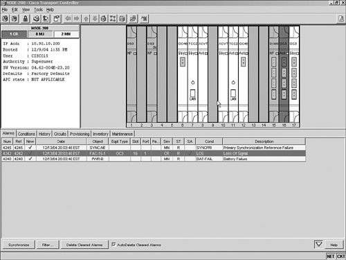 Note For the local technician, CTC is the most important tool used for alarm and trouble management. When you view the Alarms window, you will notice that there are different colors in both the graphical shelf section and the tab section of the window. Red is associated with a critical alarm. Gold is associated with a major alarm. Yellow is associated with a minor alarm. You can also see alarms in the Network view of CTC, as shown in Figure 12-17. Figure 12-17. CTC Network View Alarm Window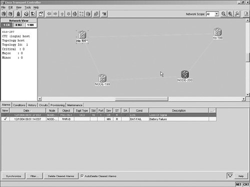 The Alarms tab of CTC provides information such as the date and time, the name of the node, the type of alarm, the card slot of the shelf, the port on the card, and a description of the alarm. You might notice in Figures 12-16 and 12-17 that both views of CTC (Shelf and Network) show some of the same alarms. Also in Network view, being able to see the entire network and the node that has the alarm is a great benefit for reducing the time needed to clear the alarm. Many times when an alarm occurs on a network, a large amount of time is spent trying to determine where the alarm is. Having the network "map" clearly shows by the different colors displayed which node or nodes have a problem. When alarms are displayed in the tab area of the window with the various colors or levels of severity, usually one of the displayed alarms is the primary alarm. That means that when the primary alarm is cleared, the rest of the lower-level (minor) alarms clear as well. For example, if a node was timed from or was receiving its clocking from the optical line instead of an external source, and there was a break in the fiber connected to that optical receiver, you would have a number of alarms in that node. Some would be more critical than others, such as loss of signal (LOS), and some would be synchronization reference alarms. After viewing all the alarms, you would have to select the most critical alarm to be cleared. In this example, you would try to determine the reason for the LOS. If the fiber cable had been cut, you would have to wait until the parties responsible for the cable repair completed the repairs. You would then see the alarms associated with this problem clear automatically because the optical receiver recognized the signal coming from the optical transmitter at the node on the other end of this particular span. In addition to alarms, conditions are events that could become alarms or that indicate some sort of abnormality. An example of a condition that could become an alarm is a bit error condition. Bit errors can be caused by many things, including dirty fiber connectors, bad splices in the cable, too much loss in the fiber span between nodes, and a bend radius violation in a fiber jumper. Any of these could cause a "dirty" or unrecognizable signal to be received, resulting in bit errors. These bit errors are counted, and when a certain threshold is crossed, an alarm is generated. Different threshold levels generate different levels of alarms, such as minor, major, or critical. A condition could also indicate that an abnormal condition exists in the system. An example of this type condition is an interface card, such as a DS-1, DS-3/STS-1, or optical card (OC-N), that might have been placed in loopback mode for testing purposes. An interface card in loopback mode is an abnormal condition and is displayed under the Conditions tab. Database BackupThe ONS 15454 uses the two TCC2 in the shelf for redundancy. Each of these processors contains all the system software of a specific release, all the provisioning and options you input when you turn up the system, and the CTC craft interface GUI, as shown in Figure 12-18. Figure 12-18. Database Backup and Restore Window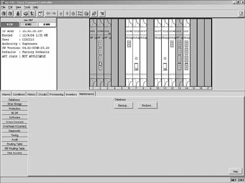 A time might come when you need to upgrade a system release, perform some type of maintenance procedure, or completely replace a node that has been destroyed by a disaster. These require "backing up" the system database in its current working configuration as a precautionary measure or to "restore" a system that has been replaced. The system database can be backed up to a PC file or a CD. Some companies set up a routine to periodically back up all node configurations in a network as part of the restoration plan. In large networks, this task is typically performed from a network operation center (NOC) or some other centrally located facility. Database RestorationRestoring a node typically is done after a node has been destroyed, a failure has occurred and standard troubleshooting methods do not resolve the problem, a new node has been installed, or possibly the TCC2 cards have been replaced. Detailed procedures for database backup and restoration can be found in the Cisco 15454 ONS Procedure Guide. Card SparingCard sparing means that maintenance spares of the critical cards for the ONS 15454 system are maintained in a protected location. These spares can be used in the rare case of a card failure in the system. Detailed information on replacing failed cards can be found in the Cisco 15454 ONS Procedure Guide located at http://www.cisco.com/en/US/products/hw/optical/ps2006/tsd_products_support_series_home.html. Software UpgradesWhen the ONS 15454 shelf and the common cards (TCC2, XC-VT, or XC-10G) are received from a supplier, the TCC2s come with the current system software release loaded on the cards, along with CTC. As with all systems that are software based, they might need to be upgraded to a newer release. The reason for the upgrade might be to add a new feature that the current release doesn't have, or a maintenance release might be required. In either case, the ONS 15454 can be upgraded to a newer release by using CTC and access to the new release from a CD or a file. To perform a software upgrade, you must verify that no alarms or conditions exist in the node being upgraded. If any alarms or conditions are present, they must be cleared before software activation, as shown in Figure 12-19. Figure 12-19. Software Upgrade View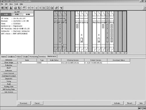 The TCC2 card has two memory partitions for performing software upgrades: There is a "working version" location and a "protect version" location. When you log into the node in Shelf view and click the Maintenance tab and the Software tab, you will see the software upgrade window. At the top of the window, you will see fields for the node name, node status, working version, protect version, and download status, along with the Download, Cancel, Activate, and Revert buttons. Two memory locations allow the TCC2 card to be loaded with a newer release in the protect version location while the system continues to operate on the working version location. Clicking the Download button opens a window to browse for the location of the new release. The download process then begins, and the new release is loaded into the protect version location. When the download is complete, the next task is to activate the new release by clicking the Activate button. Software ActivationActivation of the new release causes the node to reboot, which logs you out of the node. When the reboot is complete and you have logged into the node, click the Maintenance tab and the Software tab to view the upgrade window. You'll notice that the new release is in the working version location and that the prior release is now in the protect version location. The system is now operating on the new release. Software ReversionIf problems occur with the new release, you have the option to revert to the protect version by clicking the Revert button. This causes the system to reboot onto the prior release, which is still in the TCC2 card. This is the ONS 15454 method of recovering a system that might have failed a software upgrade. Keep in mind that any new provisioning additions are lost through the reversion process. |
EAN: 2147483647
Pages: 140