ONS 15454 ML-Series Interface Cards
| The ONS 15454 ML (Multilayer)-Series cards are essentially Layer 3 switches embedded in the SONET/SDH transport system. These cards are used to efficiently transport Ethernet frames between two or more locations on the network by using nondedicated SONET/SDH circuit links. Unlike the G-Series and CE-Series Ethernet cards, which use dedicated or "nailed-up" point-to-point connections over the MSPP network, the ML Series uses shared pathways to link two or more locations, providing a VLAN across a metro or regional area. The ML family consists of three cards. The ML1000-2 card is a GigE interface card; the ML100T-12 and ML100X-8 are Fast Ethernet interface cards. Each of the three ML-Series cards uses the same basic hardware and software, and has similar features. The primary difference between the cards is in their Layer 1 faceplate user-side interface types. Table 7-6 summarizes the Layer 1 interface features for each of the three card types.
As shown in Table 7-6, each ML-Series card has both an ACT (Active) and a LINK LED for each interface port. The ACT and LINK LED states have the following meanings for all cards:
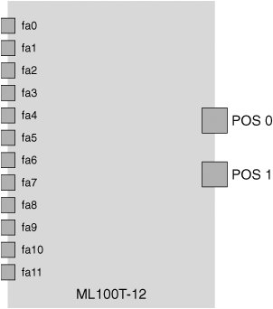
Each ML-Series card has two virtual Packet over SONET/SDH (POS) ports, which interface the faceplate Ethernet ports to the SONET/SDH ring. These POS ports are administered through the Cisco Internetwork Operating System and can be thought of as the "trunk" or network-side ports for the ML-Series cards. They function in a manner comparable to the way that OC-N/STM-N ports operate in a SONET/SDH interface card. These POS ports support CCAT or VCAT circuit types, as well as a software-based LCAS. The POS ports are called POS0 and POS1 in the Internet Operating System (IOS) software interface. They can be provisioned in a point-to-point manner with POS ports on other Ethernet cards in the network, or as East- and West-facing interfaces in a metro-/regional-area Ethernet overlay ring configuration such as resilient packet ring (RPR). RPR is discussed in greater detail later in this chapter. Figure 7-7 illustrates the POS ports and Ethernet ports for an ML100T-12 card. Figure 7-7. ML100T-12 Ethernet Interface Card: POS and Fast Ethernet Ports The ML-Series cards are provisioned and managed by a combination of CTC and Cisco IOS software. Cisco Transport Manager (CTM), which is the element management system (EMS) for multiple Cisco networking equipment (including the ONS 15454), can also be used for provisioning and managing the ML-Series cards. IOS software is the primary user interface for the ML-Series cards and is used for tasks such as Ethernet interface configuration, bridging configuration, VLAN configuration, and RPR configuration. CTC is also used for configuring and managing the ML Series, and is required for SONET/SDH circuit provisioning to link the ML-Series card(s) with other Ethernet cards in the SONET/SDH ring. This cannot be done using the IOS command-line interface (CLI). CTC can be used for the following actions related to the ML-Series cards:
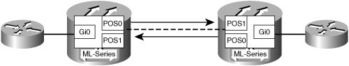
ML-Series Card Transport Architecture ExamplesFrom a transport network perspective, the ML-Series cards can be used several different ways in a SONET/SDH network. In this section, you will learn three different options for ML-based network topologies, including point-to-point, hub and spoke, and shared resilient packet ring (RPR). The type of network topology implemented depends on several factors, including the traffic pattern required and the availability of fiber facilities between ONS 15454 locations. Point-to-Point Transport ArchitectureML-Series cards can be connected in a point-to-point design to transport data between two MSPP nodes in a SONET/SDH ring. Figure 7-8 shows this type of network. Figure 7-8. ML-Series Point-to-Point Network Application Example RPR Transport ArchitectureRPR is a network architecture designed to reliably transport Ethernet frames at high speeds over local, metro, or regional optical-fiber ring networks. RPR is a Layer 2 technology. It was standardized by the IEEE in 2004 and is known as IEEE 802.17. The current generation of Cisco ONS 15454 ML Series uses a prestandard implementation of RPR and does not fully comply with the IEEE standard. A discussion of differences between IEEE 802.17 and ML-Series RPR comes later in this chapter. RPR is used in lieu of STP or Rapid Spanning Tree Protocol (RSTP) to ensure loop-free transmission with faster network convergence time in the event of a failure. Unlike STP or RSTP, RPR uses spatial reuse of bandwidth on the SONET/SDH network and does not need to block redundant paths. A detailed description of RPR follows in this section, but first review the following key benefits of ML-Series RPR:
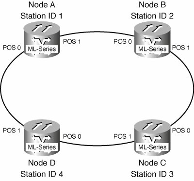
RPR Operation in the ONS 15454 ML-Series CardsTo explore the application and operation of RPR using the ONS 15454 ML-Series interface cards, consider the example shown in Figure 7-9. In this example, you want to connect four locations with an ONS 15454 SONET MSPP OC-48 UPSR ring, and you want to allow any-to-any Ethernet connectivity among all locations with carrier-class (less than 50 ms) failover in the event of a facility failure. This can be provisioned using ML-Series cards in an RPR network architecture. Each node will contain an ML1000-2 card installed in Slot 5. See Figure 7-10 for a typical node configuration in this network. Figure 7-9. ML-Series RPR Network Application Example Figure 7-10. Typical Node ConfigurationML-Series RPR Network Application Example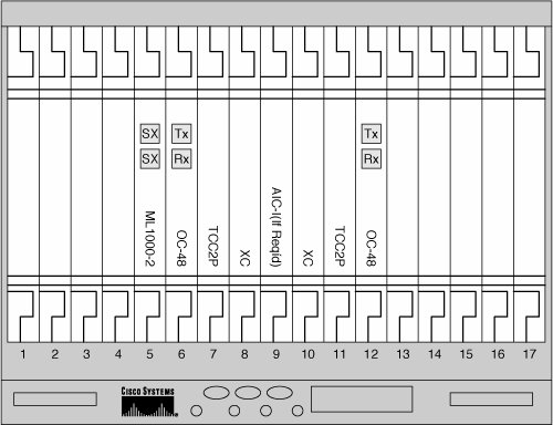 As shown in Figure 7-9, you connect the ML-Series cards installed in each of the nodes with a point-to-point, unprotected (from a Layer 1 ring standpoint) SONET circuit, connecting POS port 1 at one node to POS port 0 at the next adjacent node. For example, Node A POS port 1 is connected to Node B POS port 0. Again, these circuits are provisioned as unprotected because the failover protection is provided through the Layer 2 RPR instead of the Layer 1 SONET protocol. As previously mentioned, multiple circuit sizes can be used based on the bandwidth required between ML-Series cards participating in the RPR. Table 7-7 shows the available circuit sizes that can be provisioned between POS ports on ML-Series cards.
To provide the maximum amount of bandwidth between ML-Series cards, STS-24c circuits are provisioned between network-adjacent POS ports in our example network. These circuits can be provisioned using CTC. Table 7-8 provides a summary of the circuits provisioned for the RPR.
When virtually concatenated circuits are used with the ML-Series cards, a software-based LCAS can be used. ML-Series LCAS allows for the automatic addition or removal of a VCAT circuit member in case of the failure or recovery of a SONET/SDH facility. For example, suppose that you are using STS-12c-2v (two virtually concatenated STS-12c circuits) for the RPR instead of single STS-24c circuits in a 2-Fiber SONET BLSR. You could provision one of the two members of the STS-12c-2v as a Protection Channel Access (PCA) circuit. This PCA circuit would be dropped in the event of a line protection switch, but LCAS would allow this member to be dropped from the VCAT group and the link would continue to function with half the normal bandwidth. Software-based LCAS differs from the hardware-based version primarily because it is not errorless in operation. Each of the ML-Series cards installed in the ONS 15454 nodes is designated with a unique RPR Station ID: The Node A ML-Series card is assigned to be RPR Station 1, Node B is RPR Station 2, Node C is RPR Station 3, and Node D is RPR Station 4. Note In some cases, multiple ML-Series cards might be installed in the same ONS 15454 node and might be participating in the same RPR. This could be the case if card redundancy is required to provide a very high level of network availability at one or more MSPP locations. In this scenario, the two ML-Series cards still have unique RPR Station IDs, even though they are located in the same node. Each ML-Series card can insert traffic onto the RPR on either the POS0 or POS1 interfaces, and Ethernet frames are stripped from the RPR network at either the source or destination RPR station, depending on the traffic type. Frames are forwarded onto the RPR using either the POS0 or POS1 based on the following criteria:
ONS 15454 ML-Series RPR Frame FormatThe RPR framing is added to each Ethernet frame for transport on the RPR, and is removed at the egress ML-Series port. The RPR frame format on the current ML Series is Cisco proprietary. Figure 7-11 shows the RPR frame format and encapsulation of an Ethernet frame. Figure 7-11. ML-Series RPR Frame Format and Encapsulation of an Ethernet Frame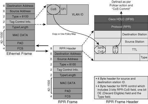 The RPR header includes the following:
ML-Series Bridge GroupsUnlike many Layer 2 switches, such as the Cisco 6500 series, the ML-Series cards forwards no traffic by default, including untagged frames and frames tagged as VLAN 1. For any traffic to be bridged by the ML Series over the RPR, one or more bridge groups must be created. The bridge group controls which ports traffic can be forwarded to and which VLANs can be forwarded on those ports. The bridge group can be compared to the cross-connect matrix of the SONET/SDH network node, in that each bridge group on the ML Series is locally significant (like the cross-connect matrix on an individual ONS 15454 node) and provides local bridging between the selected interfaces on the ML-Series card. Configuration of bridge groups can be accomplished using the IOS CLI to the ML Series. Figure 7-12 shows the relationship between the ML-Series interfaces, including the physical client interfaces, the virtual POS interfaces, and the RPR through the bridge group. Each bridge group is configured with a bridge group number in the range of 1 to 255. Ethernet or GigE interfaces (or subinterfaces) are associated with bridge groups as required. The ML-Series card bridges traffic among the interfaces configured with the same bridge group. Any interface that is not configured with a bridge group cannot forward bridged traffic. For bridge groups that need to be connected to the RPR ring, the bridge group is configured to a subinterface on the RPR interface. Figure 7-12. Ethernet Bridging over RPR (Bridge Group and VLAN)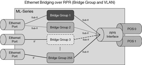 RPR OperationML-Series cards with the RPR implementation prevent loops by using source and destination station frame stripping, and by using the RPR header information. If a facility failure occurs, such as a fiber cable cut, frame loss is prevented through a wrapping procedure executed within the RPR protocol. The forwarding table in the ML Series is implemented with high-speed content addressable memory (CAM). When a frame is received and a database lookup is done from SONET/SDH, a typical Layer 2 learn occurs for the source MAC address; the source station ID is also saved. Each ML-Series RPR card can handle an Ethernet frame in three ways: with bridging, pass-through, and stripping. Each of these is briefly described as follows:
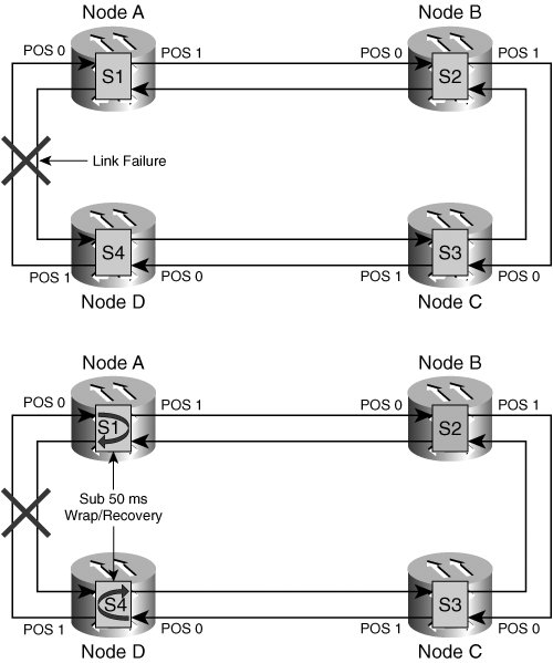
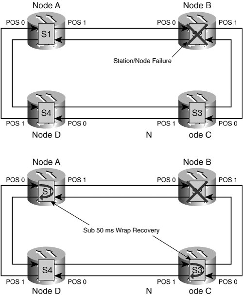
To further understand each of these operations, examine how some frames are handled in your example RPR network. In Figure 7-13, you can see the sequence of events involved in transporting a unicast packet from a router connected to the ML-Series card in Node A (RPR Station 1) to a router connected to the ML-Series card in Node C (RPR Station 3). Assume that this is the initial Ethernet frame added from Station 1. Figure 7-13. RPR Operation: Unicast Frame Transport from Node A to Node C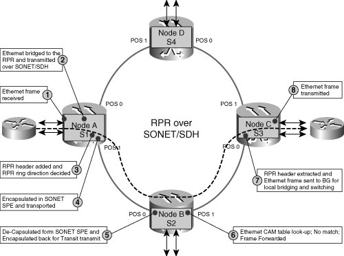 The frame arrives at the ML1000-2 card on client interface GigE 0 (gi0). The Station 1 ML Series adds the RPR header to the Ethernet frame and sets its station ID (1) in the Source Station field of the RPR header. Station 1 also sets the destination station address in the packet to the well-known 0x00 address to flood the packet onto the ring. Station 1 then determines the direction of transit on the RPR ring, based on the previously mentioned algorithm. In this example, assume that the packet is transmitted in the clockwise direction, which is the link from Node A to Node B, using the POS1 interface. When Station 2 (which is the ML-Series card located in Slot 5 at Node B) receives the packet on its POS0 interface, it checks the source station ID and determines that it did not originate this packet. Station 2 then examines the destination station ID and finds that it is not a transit packet because the destination station is set for 0x00. Therefore, Station 2 must perform a lookup in its bridging table. Station 2 performs a MAC lookup for the source address MAC and completes a standard MAC learning. It also learns the source station from the packet and saves it in the CAM table. Because Station 2 finds no match in the bridging table lookup, it floods the packet forward on the Node B to Node C link using its POS1 interface. Any subsequent station on the RPR would perform the same operation as Station 2 until the packet arrives at the POS0 interface of the proper destination station, which, in this case, is Station 3. If none of the other stations participating in the RPR can find a match for the destination address MAC, the packet eventually reaches the originating station (in this case, Station 1 on its POS0) and is dropped because the source station ID matches and the bypass flag is not set. Figure 7-14 illustrates the RPR operation for the initial frame transmitted from Station 3 to Station 1. Because this frame is added at one of the client interfaces at Station 3, it is not flooded as in the previous example because the bridging table lookup finds the destination address MAC in the table along with the destination station ID. This information was learned from the initial packet sent from Station 1 in the previous example. The frame is encapsulated with the RPR header, Station 3's ID is set as the source station, and Station 1's ID is set as the destination station. Station 3 then performs the calculation to determine the direction of transmission onto the RPR. In this case, it is transmitted clockwise on the link between Node C and Node D using its POS1 interface. Figure 7-14. RPR Operation: Unicast Frame Transport from Node C to Node A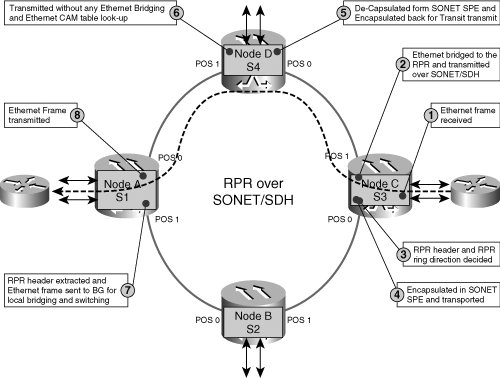 Station 4, which is the ML-Series card located in Slot 5 of Node D, checks the source station in the frame header and determines that it did not originate the frame. Station 4 then can determine that this is a pass-through frame by looking at the destination station ID, which is set for Station 1. Therefore, it forwards the frame onto the ring using its POS1 interface. When Station 1 receives the frame on its POS0 interface, it determines that the destination station is a match. A bridging table lookup and learn are performed, with two possible outcomes. In the normal case, a match is found in the table and the frame is forwarded out one of the ML-Series card's front client ports. In this case, the frame is not transmitted back out onto the RPR. However, if the destination address MAC is not found, the frame is flooded back onto the RPR using the POS1 interface. In the second scenario, the frame will eventually be removed from the RPR by the originating station, which is Station 3 in this example. Station 3 would also invalidate its CAM entry used to send the destination address MAC to Station 1. RPR Operation in Failure ScenariosThe ML-Series RPR implementation efficiently handles failure scenarios, such as fiber facility failures or node/station failures. To illustrate the operation of the RPR in a fiber cut, refer to the example network shown in Figure 7-15. Figure 7-15. RPR Operation During Fiber Facility Failure When the fiber facility between Nodes A and D is cut, the failure is detected in less than 50 ms, and the RPR stations (in this case, stations 1 and 4) transition into "wrap" mode and can be said to be "wrapped." When in wrapped mode, the RPR stations wrap packets back into the direction opposite the facility failure. Figure 7-15 shows this wrapping operation. To understand how packets are handled under the wrap failure-recovery system, examine a unicast packet sent from Node B to Node D. After the adjacent stations 1 and 4 detect the cut, a unicast packet is added at Station 2 (Node B) with a destination station of 4 (Node D). Station 2 encapsulates the packet with the RPR header, adds its station ID as the source station, and performs a calculation to determine the direction that the packet will traverse the ring. In this case, the packet will be forwarded over the link from Node B to Node A in the counterclockwise direction on the ring, using the Node B POS0 interface. After receiving the packet on its POS1 interface, Station 1 would normally inspect the packet's destination station ID, see that it is intended for Station 4, and forward it out using its POS0 interface. However, because of the fiber cut, Station 1 is in the wrapped condition. Because Station 1 is wrapping, it sets the wrap flag (equal to 1), sets the bypass flag (equal to 1), assigns its station ID of 1 to the Wrap Station field, and transmits the packet back out the incoming port (POS1). When Station 2 receives the packet (on the POS0 interface), it detects that it is the originating station by finding its station ID as the source station. However, because the bypass flag is set, it resets the bypass flag (equal to 0) and performs a pass-through operation, sending the packet back out onto the ring using its POS1 interface. When Station 3 receives the packet on its POS0 interface, it determines that it is not the originating station (because the source station is set as Station 2) and that it is not the intended destination (because the destination station is set as Station 4), so the packet is treated as transit and forwarded out onto the ring using its POS1 interface. Station 4, which is the ML-Series card in Slot 5 at Node D, receives the packet on its POS0 interface. After determining that it is the destination station, it performs a lookup and forwards the packet out of a client port. The packet is then not forwarded back onto the RPR (dropped). Another possible failure scenario is the loss of a station in the RPR because of facility isolation or catastrophic node failure (such as a loss of power to the MSPP node). In this case, the adjacent nodes to the failed station perform a wrap and packets are handled much as described in the previous fiber cut scenario. A special case of this scenario occurs when the station that fails (or is removed) is the intended destination of a packet. In this situation, when the packet arrives at the first wrapping node, it sets the wrap and bypass flags (equal to 1) and wraps the packet. All other nodes then perform a pass-through operation as the packet circles the ring in the opposite direction until it arrives at the other wrapping node, where it is dropped. Figure 7-16 shows this situation. Figure 7-16. RPR Operation During Single-Node Isolation/Failure RPR Spatial ReuseNow that we have examined the operation of the RPR, including the capability to avoid loops and recover from facility and node failures, it is easier to understand the capability of the RPR network to simultaneously transmit packets among multiple station sets on the ring. This is shown in Figure 7-17: Packet flows are simultaneously occurring between Station 1 and Station 3 (Frame A), Station 4 and Station 5 (Frame B), and Station 7 and Station 10 (Frame C). Figure 7-17. RPR Spatial Reuse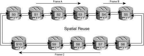 Provisioning RPR Using the ONS 15454 ML-Series CardsSetting up an RPR topology with the ML-Series cards can be accomplished using CTC and the Cisco IOS CLI for the ML Series. Configuration can also be accomplished using CTM, which is Cisco's integrated optical element-management system. Chapter 15, "Large-Scale Management," covers CTM in greater detail. This section concentrates on RPR provisioning using CTC. The network in Figure 7-18 shows the process of creating the RPR. In this example, a group of seven ML-Series cards installed in four different ONS 15454 (SONET) MSPP nodes (participating in an OC-48 UPSR) will be placed into the RPR, with three VLANs, as shown in the figure. Figure 7-18. ML-Series RPR Network Example Configuration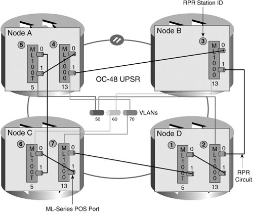 CTC RPR Circuit and Framing Mode ProvisioningProvisioning the "backbone" circuits between the RPR stations in CTC is a fairly straightforward process. This is essentially the same process as provisioning a normal TDM circuit, such as a DS1 or DS3; the primary difference is that the RPR circuits are typically provisioned as unprotected. This is because failover is provided using the RPR station wrap functionality instead of SONET protection switching. A high-level overview of this circuit-provisioning process in CTC is provided in the following steps:
Figure 7-19 shows an example of the CTC Detailed Circuit View for an RPR circuit. Figure 7-19. CTC Detailed Circuit View for an Unprotected RPR Circuit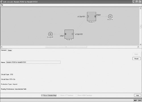 In addition to the SONET/SDH circuit provisioning, the framing mode for the ML-Series card is configured using CTC. This is accomplished in card view for the ML-Series card, under the Provisioning tab and Card subtab. Framing mode options are HDLC or GFP-F. HDLC is the default. Peer POS ports must have the same framing mode. Note The ML-Series card will reboot if the configured framing mode is changed. ML-Series IOS Configuration File ManagementAfter provisioning the circuits in CTC, the remaining provisioning required for RPR functionality can be performed in the ML-Series IOS CLI. Each ML-Series card is configured independently. The ML-Series CLI is typically accessed either by using the console port located on the faceplate of the card (using the RJ-11 to RJ-45 adapter cable that ships with the ML-Series cards) or by opening an IOS CLI session in CTC. It can also be accessed using a Telnet session. You can load the startup configuration file that the ML Series requires using CTC. Cisco supplies a sample IOS configuration file, called Basic-IOS-startup-config.txt on the ONS 15454 software CDs. CTC can also be used to load a user-supplied configuration file. If the configuration file is uploaded to the Timing, Communications, and Control Cards (TCC+, TCC2, or TCC2P) before the ML-Series card is installed, the ML Series is download and applies the file when it is installed. This allows the card to immediately begin functioning as a fully configured card. If the configuration file is uploaded after the ML Series is installed, the ML-Series card will need to be reset to use the file. The copy-run-start command executed in the CLI copies the current running configuration on the ML-Series card to the Flash memory of the ML Series. This is also saved to the node's database-restoration file after approximately 30 seconds. If the user performs a database backup, this IOS configuration file is stored in the backup file along with all of the other provisioning in the node. The ML-Series card's IOS configuration file can be managed by right-clicking the ML-Series card in CTC shelf view, which opens a shortcut menu. This is also one way to open a Telnet IOS CLI session with the card. RPR Provisioning and Verification in the IOS CLIIn the example to demonstrate the IOS RPR configuration process, place all seven of the ML-Series cards in the four-node ring into the same RPR. Two of the cards, the ML100T-12 in Slot 5 in Node A and the ML1000-2 in Slot 13 of Node C, will participate in VLAN 50. Likewise, VLANs 60 and 70 will also be used between two stations (each) in the RPR, as shown in Figure 7-18. Table 7-9 shows a step-by-step configuration of the ML-Series card in Node D, Slot 5. Assume that an IOS session has been established with the ML-Series card using the Open IOS Session shortcut option in CTC shelf view. A similar configuration is performed for each of the other ML-Series cards that will be placed into the RPR.
To verify the configuration, the show running-config command can be entered in privileged mode. Example 7-1 shows sample output for this command. Note The other Fast Ethernet interfaces (1 through 11) have been omitted for clarity. Example 7-1. Verifying RPR Configuration for ML-Series Card in Node A, Slot 5
You can use the show vlans command to view the interface VLAN configuration, as shown in Example 7-2. Example 7-2. Displaying Interface VLAN Configuration
Now configure all the other ML-Series cards in the RPR in a similar manner. Table 7-10 shows the parameters used in the command series to configure the network to match the functionality shown in Figure 7-18.
When all other ML-Series cards in the RPR are configured, you can use the show cdp neighbors command to see the other RPR stations, as shown in Example 7-3. Example 7-3. Displaying Neighboring RPR Stations
|
EAN: 2147483647
Pages: 140