Cross-Connect Cards
| The cross-connect (XC) cards are required for operation of the ONS 15454 MSPP system and are installed in a redundant pair in shelf Slots 8 and 10. Three versions currently are available from Cisco: XCVT, XC10G, and XC-VXC-10G. Each version has both a high-order (STS-N) cross-connect fabric and a low-order virtual tributary (VT1.5) fabric. All three perform the same basic functions, but they feature varying cross-connect capacities. Table 6-3 summarizes the high-order and low-order cross-connect capacities of the XCVT, XC10G, and XC-VXC-10G cards. The meanings of these capacities are covered later in this section.
The XCVT, XC10G, and XC-VXC-10G have green cross symbols on their faceplates, which correspond to matching symbols on the front of the ONS 15454 shelf assembly. This serves as an aid in easily identifying the correct location to install the cards. The XC card types are the only cards allowed in Slots 8 and 10 for the MSPP, and both slots should always be equipped. Cisco does not support the operation of the ONS 15454 MSPP system with only a single XCVT, XC10G, or XC-VXC-10G installed. Although the system will technically function with only a single card, the second card is necessary for redundancy and to allow for continuity of system traffic. An earlier version of the cross-connect card is called simply the XC card. This older version provides a 288 STS-1 fabric, which is the same size as the high-order fabric in the Cross-Connect Virtual Tributary (XCVT). However, the XC card does not support low-order (VT1.5) grooming, and systems that are equipped with the XC card cannot drop DS1 circuits. Although it can be installed in some existing systems, Cisco no longer produces the XC card. The XCVT, XC10G, and XC-VXC-10G cards have only two faceplate LEDs. The red FAIL LED illuminates during a reset and flashes during the boot process to indicate that the card's processor is not ready for operation. If the FAIL LED does not extinguish, this is an indication that the card has failed and needs to be replaced. The ACT/STBY LED indicates whether the card is the active (green) or standby (amber) card in the redundant pair. Cross-Connect Card BandwidthEach of the three cross-connect card types has a high-order (STS-1) and low-order (VT1.5) capacity, as shown in Table 6-3. For example, the XC10G card has an STS-1 capacity of 1152 STS terminations. Each STS-1 circuit requires at least two terminations, one for entering (ingress) and one for exiting (egress) the cross-connect matrix. Therefore, a single Bidirectional Line Switch Ring (BLSR) circuit, a pass-through circuit, or an unprotected circuit consumes two terminations of the available capacity. In a Unidirectional Path-Switched Ring (UPSR) circuit-termination node, an STS-1 circuit consumes three matrix terminations because of the signal bridging that occurs to enable UPSR protection. As an example, a DS3 circuit in a UPSR termination node would use three STS-1 terminations (of the available 1152 for the XC10G or XC-VXC-10G, or the available 288 for the XCVT). VT1.5-Level cross-connections are made via logical STS ports in the VT matrix of the various cross-connect cards. The XCVT and XC10G VT matrices have 24 logical STS ports (24 STS ports x 28 VT1.5/port = 672 VT capacity); the XC-VXC-10G has 96 logical STS ports (96 STS ports x 28 VT1.5/port = 2688 VT capacity). To fully use the VT matrix capacity, each STS port must carry 28 VT1.5 circuits. Because of this, stranded capacity can occur when using, for example, a DS1-14 card as a circuit source/destination. Because the 14 DS1s from the DS1-14 card's 14 ports are carried to the cross-connect matrix on an STS-1, the remaining 14 VT1.5 capacity within the STS-1 is unused on the VT cross-connect matrix. To further aid in understanding the way the cross-connect matrixes operate on the ONS 15454, see Figures 6-4 and 6-5. Figure 6-4 shows a VT1.5 circuit from a DS1-14 card in a BLSR termination node; Figure 6-5 shows the same circuit in a UPSR termination node. Note the matrix use information shown for each of the figures. Figure 6-4. VT Matrix Use for a DS1 Circuit in a BLSR Termination Node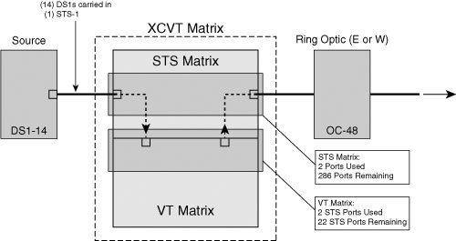 Figure 6-5. VT Matrix Use for a DS1 Circuit in a UPSR Termination Node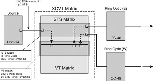 Note The transition connections between the STS (high-order) matrix and the VT (low-order) matrix are not counted when calculating ports used on the STS (high-order) matrix. |
EAN: 2147483647
Pages: 140