Chapter 16: Bridging Two Networks
|
|
Building the Bandwidth Expander
Building a tin can gain antenna isn't difficult at all. The simplest kind consists of one tin can, a type N female coaxial connector, and less than 2" of #12 copper wire. The work required consists of a little math, a little measurement, and some minor handywork with an electric drill and a soldering iron. In this subtopic, I'll provide gruesomely detailed instructions for how to build one.
After that, well, the field is ripe for experimentation. I encourage you to study up on the theory and try different things, and I'll point out some of the possibilities that you can pursue.
Choosing Your Can
In an ideal world, you could just order the precise length of metal cylinder (ideally silver-plated copper or brass) at the precise diameter your calculations specify, say, 93 millimeters. Doubtless there is somebody somewhere in the world who will sell you tubing like that, but if you have to ask what it costs, you can't afford it.
No. We're using tin cans here. So we have to look and see what's out there, and then decide what available sizes fit within the constraints of the RF physics that govern waveguide operation.
Diameter is the key. For any given frequency, the diameter of a useful circular waveguide is constrained by a minimum and a maximum value. Within these two bounds, your waveguide will conduct Radio Frequency (RF) energy at the given frequency (for us, within a band centered on 2.45 GHz) with the least loss of power on transmit and signal on receive.
These two bounds define the waveguide diameter limits within which a single wave propagation mode (called TM 11) predominates at a given frequency. Above and below the bounds, other propagation modes begin to operate as well, and the lossiness of the waveguide increases.
If the notion of a 'propagation mode' is meaningless to you, don't sweat it. Having a complete understanding of waveguide physics isn't necessary to make a good waveguide antenna, but the physics are very cool nonetheless, and I encourage you to read up on it. (The best treatment I've seen is in the ARRL UHF/Microwave Experimenter's Manual, Chapter 5.)
So what are the bounds for our frequency, which is 2.45 GHz? (2.45 GHz is roughly the center of the band of frequencies used by Wi-Fi gear.) The lower diameter limit in centimeters is defined by the 'free space' wavelength at 2.45 GHz divided by 1.706. The wavelength there is 12.25 cm:
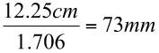
The higher diameter limit is defined by the wavelength divided by 1.3065:
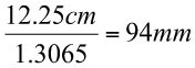
There's our bounds: 73 mm on the low side, and 94 mm on the high side. Explaining where the two constants 1.706 and 1.3065 come from is more than I can tackle in this book, but they're consequences of the geometry of circular waveguides. You'll have to trust me on it-or go read the ARRL UHF/Microwave Experimenter's Manual.
So… do we aim down the middle and pick a can with a diameter of about 85 mm? (This would be convenient, as by total coincidence that's one of the commonest can sizes in your local supermarket!) Not necessarily, unless you can find an 85 mm can that's long enough. The problem is that the efficiency of a circular waveguide doesn't peak halfway between the bounds. It's mostly flat inside the bounds, and decreases (with increased lossiness) in both directions outside the bounds.
Furthermore, this increase of lossiness outside the bounds is not symmetrical. It goes up much more quickly as your waveguide gets smaller than as it gets larger. In fact, going outside the bounds on the large side doesn't lose you all that much for the first fifteen or twenty percent.
Another advantage of choosing your waveguide on the larger end is that the position of the probe (the quarter-wave spike that transfers RF energy between the waveguide and your coax pigtail) is much less critical there, so small errors in drilling for the N connector won't make as much difference.
So what are we faced with? If you could choose your size arbitrarily, it would be 94 mm. I'm not sure about Europe, but in the US I've found nothing at that size. I'm already laughing at the thought of thousands of Wi-Fi users around the world searching the canned food aisle and coffee section of supermarkets with ruler in hand seeking the perfect can. I measured enough to say that cans in the U.S. tend to be in one three sizes: 3 3/8", 4", and 4 3/16", which in metric terms are 87, 100, and 105 mm, respectively.
Of these three, only the 87 mm can is inside our diameter bounds. Can we use the others? Yes. This isn't like crossing the streams in Ghostbusters -in fact, a 100 mm waveguide will work fine for Wi-Fi, and that's the size I recommend, for two purely practical reasons: 4" (100 mm) cans are very common, and the 4" cans that are out there are longer than the 3 3/8" cans. They are long enough, in fact, so that you can use a single tall 4" can (like a 1-pound coffee can) as an effective waveguide antenna. If you decide to use the 3 3/8" cans, you might have to solder two or three together, end-to-end, which is a lot more work. (I found a 5 5/8" tall one in that diameter, full of Hunt's Spaghetti Sauce, and used it on Mark III. I don't know how common that size can is, but grab one if you can. The antenna works great, and the sauce is actually pretty good!)
So go get yourself some cans. It sounds silly and your spouse will probably want to be two aisles over, but do what I did: Take a pocket tape measure with you to the supermarket, and find something sold in a 4" can that you can force down without choking. If you're a coffee drinker, look for ground coffee in the 1-pound size. (These days, you may only get 12 ounces of coffee in that size can.) That's a relatively tall can (which we want) and virtually all such cans are 4" in diameter. In fact, I consider the 1-pound coffee can the best all-around can for use as a waveguide antenna.
Another possible prospect is the 46-ounce tomato juice can. It's 7" long and 4 3/16" diameter (about 105 mm.) The greater length gives you a little more gain, which compensates for the slightly greater loss inherent in its diameter. The other problem with tomato juice cans is that they have fairly pronounced corrugations along most of their length. These increase the scattering of RF energy within the can and thus reduce the can's effectiveness as an antenna.
Dinty Moore Beef Stew and various Chef Boy-Ar-Dee glop lunches come in 4" diameter cans, as do various species of canned fruit. They aren't very long cans, so if you drink neither coffee nor tomato juice, (and can't find that variety of Hunt's Spaghetti Sauce) you may have to solder two or three ravioli or peach half cans endtoend to get sufficient gain to make the work worth the bother. (Soldering cans together requires a hefty soldering iron, a jig to hold the cans together, the right kind of solder, and some practice. Teaching structural soldering is outside the charter of this book. If you're not already an ace, avoid it if you can.)
Don't use a 2-pound coffee can, which at 6" diameter is way outside the diameter bounds for a 2.45 GHz waveguide. An antenna performance 'shoot-out' published on the Web showed that 2-pound coffee cans do not perform as well as the narrower cans. For more information about this, visit the following Web site:
http://www.turnpoint.net/wireless/has.html
If you can find a steel tennis ball can it might be worth a try. Such cans are a little under the ideal diameter (mine measures 75 mm) but they're 8" long and have no corrugations as most larger cans do. They're shaped a lot like Pringle's potato chip cans, in fact, but since they're made of metal they will actually work.
Ideally, the can should be clean and not dented nor distorted in any dimension. Cans get rough handling and most do not end up as waveguide antennas. Choose a can that hasn't been dropped, dented, or otherwise bent.
You'll need a can of an acceptable size, plus a chassis-mount N-style coaxial connector. (See Figure 15.3.) The connectors are available from many places. (I order silver-plated ones, but you can do well with the ordinary zinc-plated connectors, which are half the price.) See the vendor list in Appendix A. You'll also need about 2" of #12 copper wire.
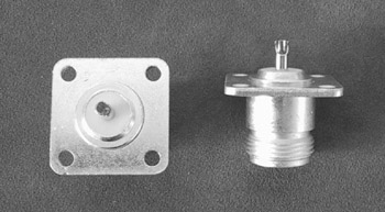
Figure 15.3: The UG-58: Chassis Mount N Connector.
The Overall Design and a Little More Math
A waveguide antenna is basically a cylinder open on only one end, with an N-type coaxial connector fastened into a hole drilled somewhere along the long axis of the cylinder. When you take the food/juice/coffee out of the can, remove one end entirely with a can opener, but leave the other end intact. Take off the label and wash the can thoroughly. If the can opener left any burrs, take a small file and file them down until they're not a threat to your hands. (Burrs won't reduce the electrical effectiveness of the antenna, but they can be razor-sharp.)
Figure 15.4 is a drawing of the finished antenna. The work to be done consists of calculating and measuring the distance from the closed end at which the connector should be mounted, then drilling a hole there for the N connector. After you measure, cut and solder the wire probe to the N connector, you mount it in the hole you drilled.
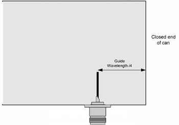
Figure 15.4: The Simplest Tin Can Antenna.
And that's it!
But before you grab your electric drill, there's some more math to be done. We need to calculate how far from the closed end of the can to drill for the N connector. The distance to measure for is the guide wavelength divided by 4.
The guide wavelength is not the same as the free-space wavelength. The free-space wavelength, as the name implies, is the wavelength of radio energy traveling through free space. The guide wavelength is the distance between successive radio wave peaks and nulls as they impinge on the walls of the physical waveguide.
A waveguide is essentially a pipe for radio waves, but radio waves do not travel in a single straight line down the center of a waveguide. They bounce back and forth off the walls, at an angle, and at any given point along the waveguide the incident waves either cancel or reinforce one another.This canceling and reinforcement creates a pattern of electromagnetic peaks and nulls within the waveguide. The distance between successive peaks (or between successive nulls) is the guide wavelength. It depends upon both the frequency of the radio waves passing through the waveguide, and on the diameter of the waveguide itself.
Understanding this completely isn't necessary to making a good antenna. What you must understand is that you have to calculate the guide wavelength for each different can size that you use. The guide wavelength for a 4" can is not the same as the guide wavelength for a 4 3/16" can. I could give you a pre-calculated table for common can sizes, but if you come up with an odd size piece of can or tubing or pipe, you'll need to crunch the numbers yourself.
The formula isn't hideous. In fact, if you're mathophilic (hah!) it may even look familiar:
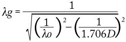
Here λg represents the guide wavelength, λo represents the free-space wavelength, and D represents the waveguide's diameter, all in centimeters. (If you haven't forgotten your junior-year math, you'll see that what we're doing here is using the Pythagorean Theorem to solve for one of the sides of a right triangle-which is key to understanding the physics, but not key to solving the equation! See the ARRL UHF/Microwave Experimenter's Manual for the full treatment.)
If you're more a coder than a mathematician, here's the formula expressed in Pascal:
GuideWL := 1 / SQRT(SQR(1/FreeSpaceWL) - SQR(1/(1.706*GuideDia)));
The three variables are all floating-point types. This should translate without much hassle into most other programming languages. Pop in 12.245 for FreeSpaceWL and the diameter of your can for GuideDia (both in cm) and turn the crank to find the guide wavelength in cm.
Drilling for the Connector
The N connector must be attached one quarter of the guide wavelength from the closed bottom of the can. Divide the guide wavelength value by 4 and write it down. For a 4" can, that will be 4.2 cm, or a hair under 1 11/16".
Note that virtually all tin cans have a bead running around their top and bottom edges. The bottom of the can is inset slightly (usually about 1/8") from the edge of this bead. Measure this inset before you mark, and take the inset length into account when you mark the drill point, by adding the inset to the quarter guide wavelength value. This value will be the distance you measure and mark from the bead edge of the can. Call it the probe offset length. See Figure 15.5.
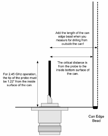
Figure 15.5: Probe Measurement Cautions.
Set the can on a flat surface, and measure as precisely as possible from the bottom of the can to the probe offset length. Put a dot at that point with a permanent marker.
Drilling into the can for the N connector might be tricky. You want to avoid pushing so hard on the side of the can that you bend the can. The best way to do it is to clamp a short length of 2 x 2 lumber in a vise so that 8" or 10" of wood extends away from the vise. If you have a drill press, you can clamp the 2 x 2 to the drill press plate with C clamps, and then offset the drill press plate as required so that the drill bit can come down on the measured point. What you want is for the wood to support the can as you drill it. See Figure 15.6.
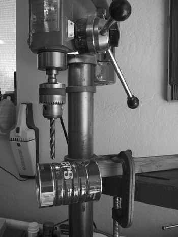
Figure 15.6: Drilling the Can.
Place the can over the 2 x 2 so that there is wood under the point where you need to drill. With a center punch, tap lightly at the center of your marked point. Then, drill a 1/8" pilot hole. The actual size hole you need to drill for the connector depends on the connector-they are not all precisely alike.
The very common and highly standard UG-58/AU 4-hole mount N female connector has a flange diameter of 15/32" (.469") and that's the hole size to drill in the can for that type of connector. The bulkhead N connector (see Figure 15.7) is designed to go through a 5/8" hole. The bulkhead connector is a little more expensive but obviates the need to drill the four additional small holes required for the UG-58.
Figure 15.7: An N female bulkhead connector.
If you're using the UG-58 connector, drill the 15/32" hole, then file the burrs with a rattail file. Insert the connector into the hole so that it's snug against the can, then mark through the four flange holes with a felt marker. Punch and drill the holes 1/8". Use 4-40 thread flat-head screws, at least 3/8" long.
A single clean 5/8" hole is all you need for the bulkhead connector.
Making the Probe Assembly
The probe is pretty simple: It's a short length of #12 copper wire soldered into the 'solder pot' of the N connector. The #12 wire is the commonest size used in residential construction wiring. You'll need at most about 2", so if you can avoid it, don't buy a whole roll! In fact, if you look around any construction site in the framing stages, you'll probably find little snippets of wire lying around everywhere. Take a few home. The #12 wire is 0.0815" thick, but that's not critical. The #10 wire will do fine, but is less common. The #14 wire is a little thin, and too easily bent.
Take about 2" of the wire, remove the plastic insulation, and get it as straight as possible. (Clamping it in a vise for an hour works well.) Solder the wire into the N connector's solder pot, which is the small protrusion opposite the connector end. Get it as close to perpendicular to the connector as you can. This may take a few tries, each of which requires re-melting the solder in the pot around the wire.
The probe length measurement must be reasonably precise. Do your best.The length is dependent only on the free-space wavelength, which for Wi-Fi is 2.45 GHz. The diameter of the can doesn't matter, and you can use the same probe in any size can suitable for a waveguide at 2.45 GHz. What you want to measure is from the inside of the can to the tip of the wire. Tin can metal varies slightly in thickness, but it hovers around .01" (one one-hundredth of an inch) and you can use that for a working value.
At 2.45 GHz the probe length is 1.22". Since it's easier measuring the probe outside the can than in it, add .01" for the sake of the tin can's thickness, and measure 1.23" from the inside surface of the mounting flange to a point on the wire. Mark and snip it with diagonal pliers. File the snipped end so that it's slightly rounded. Your probe is done. See Figure 15.8.
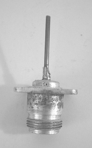
Figure 15.8: The finished probe.
All that remains is to fasten the probe into the can (as appropriate for the type of N connector you're using) and the antenna is complete. If you're using a UG-58 connector, make sure you put the heads of the mounting screws inside the can, pointing out. Do not put the 'long' ends of the screws, with nuts, on the inside!
If possible, avoid drilling additional holes into the can for mounting it. I used small pieces of thin aluminum sheet to create brackets, and drilled a hole to clear the body of the N connector. The bracket is held to the can by the same screws as the N connector. See Figure 15.9 for a close-up photo of the finished tin can antenna, including a mounting bracket I made for it by bending a strip of aluminum in a vise.
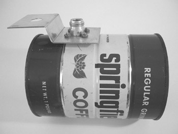
Figure 15.9: The finished tin can antenna.
What you mount the can on is more or less up to you. I chose a gooseneck mount because I had one in my junkbox, but you can mount it on anything that will keep it from moving around once it's been aimed. You can paint it, inside and out (paint on the inside will not reduce its effectiveness) and make it a little less ugly. I left Mark III unpainted because I felt it looked better that way. See Figure 15.10 for a shot of how it looks on my coffee table.
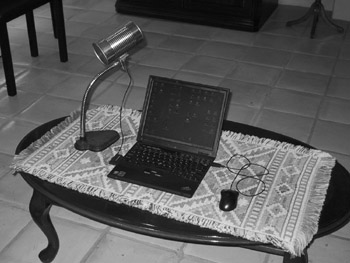
Figure 15.10: The Tin Can Expander, Mark III in use.
|
|
EAN: 2147483647
Pages: 181