Certification Objective 5.01: Create a Conceptual Model of Data Requirements
As we have already discussed, ORM is a process for designing the conceptual model for a database. ORM defines a step-by-step procedure for creating this model, called the CSDP. The CSDP contains seven steps, many of which involve checking the design to remove redundancies. In this way, CSDP incorporates the rules of normalization to ensure the database performs the task we expect from it without ambiguity, redundancy, or data loss.
The seven steps of CSDP are as follows:
-
Step 1 Transform familiar information examples into elementary facts and apply quality checks.
-
Step 2 Draw the fact types and apply a population check.
-
Step 3 Check for entity types that should be combined and note any arithmetic derivations.
-
Step 4 Add uniqueness constraints and check arity of fact types.
-
Step 5 Add mandatory role constraints and check for logical derivations.
-
Step 6 Add value, set comparison, and subtyping constraints.
-
Step 7 Add other constraints and perform final checks.
Author's Note Terms such as elementary facts, constraints, and arity will be defined later in the chapter.
In the sections that follow, we will go over each of the seven steps one at a time. As we go through the steps, we will make our way through the analysis and design of a case study. By the end of the chapter, we will have a working database model for this case.
Our case study for this chapter will be the Happy Go Lucky Employment Agency (HGL). HGL is a small agency that specializes in finding talented computer professionals in order to fill either full-time or contract positions for clients. HGL currently has eight agents working on staff, although that number often changes during extremely busy and extremely slow months. Agents work from a desk within HGL’s corporate offices, but they also need to be able to work from home or at a client’s site.
There are two interconnected parts to the employment agency business: finding quality candidates for clients and finding jobs for candidates. Often, the agent that finds the open job is not the same agent that finds the best candidate, so agents are constantly communicating with one another. Currently, this process happens over e-mail within the company, although this system frequently results in costly communication breakdowns.
HGL has decided it needs a centralized application to assist with matching available jobs and candidates. An agent with an open position will be able to search that database for qualified candidates, and an agent with an available candidate will be able to search for jobs for which the candidate qualifies. Future versions of the software may include an entire contact management system (CMS) to log agent interactions with customers and candidates, but that enhancement does not need to be included just yet.
Step One: Creating a Conceptual Model
The first step of the CSDP is the most important step of the design process. This step involves creating a list of elementary facts about the system. In ORM, an elementary fact is a sentence, written in natural language, that asserts that an object has a particular property or that a relationship between two or more objects exists.
For instance, in our case study example, we could say, “Fact 1: Each candidate has a name.” This fact happens to be a basic assertion about a known property of a Candidate object. The Candidate object has many more properties, to be sure, but each fact should relate to only one property or attribute.
Identifying the Elementary Facts
When designing a database using ORM, it is often helpful to use a subset of real data in order to validate facts and make it easier to work with them. For our purposes, let’s review the facts using a specific candidate’s data, as shown in Table 5-1.
| Exam Watch | Role descriptions are often reversible. For instance, the fact “An employee writes a report” can also be written as “A report is written by an employee.” |
Of course, the facts listed in Table 5-1 present a somewhat simplified view of a candidate. A real employment agency might need to store dozens of attributes about each candidate, including the number of years of experience for each skill, the names and addresses of previous employers, the names and addresses of educational institutions, and even a recent copy of the candidate’s r sum . Because this is just an example, we have the benefit of not having to worry about those kinds of things.
| Fact Number | Description |
|---|---|
| 1 | The candidate with Candidate ID 1234 has the name “John Smith.” |
| 2 | The candidate with Candidate ID 1234 lives at the address “123 Main Street, Anytown, CA.” |
| 3 | The candidate with Candidate ID 1234 has the phone number “(415) 555-1234.” |
| 4 | The candidate with Candidate ID 1234 can perform the skill “C programming” at an expert skill level. |
| 5 | The candidate with Candidate ID 1234 can perform the skill “SQL Server” at an intermediate skill level. |
| 6 | The candidate with Candidate ID 1234 can perform the skill “COBOL programming” at a beginner skill level. |
| 7 | The candidate with Candidate ID 1234 is available. |
Our case study also mentions the need for our database to track open jobs. In order to understand the range of values that can go into that field, we will need to examine a few more examples. Viewing only one row of data is often not enough to get an accurate representation of the data in a database. Table 5-2 lists the new facts we have gathered related to jobs.
| Fact Number | Description |
|---|---|
| 8 | The job with Job ID “T99” has the job title “Senior Programmer/Analyst.” |
| 9 | The job with Job ID “T99” is with the employer “Acme Health Labs.” |
| 10 | The job with Job ID “T99” has the status “unfilled.” |
| 11 | The job with Job ID “T99” has the type “full-time permanent.” |
| 12 | The job with Job ID “T99” pays an annual salary of $48,500. |
| 13 | The job with Job ID “T99” requires the skill “VB .NET programmer” at an intermediate skill level. |
| 14 | The job with Job ID “T99” requires the skill “SQL Server” at an intermediate skill level. |
| 15 | The job with Job ID “T99” requires the skill “Microsoft IIS” at an intermediate skill level. |
| 16 | The job with Job ID “T99” is located in “Downtown Anytown, CA.” |
From looking at Table 5-2, you can see that the fact numbers have continued in sequence from the previous list. We now have 16 facts; the first 7 facts list the candidate attributes, and the next 9 list the job attributes. We extracted these facts by looking at a couple of real-life examples of the data we need our system to capture.
One sample row of data often is not enough to capture all the potential facts of a system. Database designers need to review at least a few dozen records to check for differences within the first data row. For instance, if we looked at another candidate’s record, we might find that the second candidate is not currently looking for work. In that case, fact number 7 would not apply to this new candidate, and, therefore, we would need to create a new fact to take this new data rule into account:
| Fact Number | Description |
|---|---|
| 17 | The candidate with Candidate ID 2421 is available as of the date “05/17/2005.” |
| Exam Watch | It is often best to review many different examples of data to validate a conceptual design. |
As you may have noticed from the wording of the facts in this case study, facts in ORM are written in a specific format. Unary facts consist of an object and a property/ role. For example, if we look at fact number 7, the two components are
-
An object “The candidate with Candidate ID 1234”
-
A property/role “is available”
Binary facts define an object and its relationship to another object or value. For example, if we look at fact number 17, the three components are
-
An object “The candidate with Candidate ID 2421”
-
A relationship verb/role “is available as of ”
-
A related object or value “the date ‘05/17/2005’”
A fact can also define a relationship among three or more objects. For example, fact number 4 defines a relationship among three objects and is therefore known as a ternary fact:
-
An object “The candidate with Candidate ID 1234”
-
A relationship verb/role “can perform”
-
A related object or value “the skill ‘C programming’”
-
A relationship verb/role “at”
-
A related object or value “an expert skill level”
The number of entities involved in a fact is called the arity of the fact. A unary fact has an arity count of 1. A binary fact has an arity count of 2. Facts can have arity counts of 3, 4, or higher, but these types of facts are rare.
Applying a Basic Quality Check
Once all the facts are identified, they should be checked to make sure all of the objects are well identified. An object in ORM is either an entity or a value. A value is either a number or a string, whereas an entity represents a real world object. For instance, “candidate” is an entity, whereas “John Smith” is a value. Each of the facts we have listed should have clear entities, values, or both.
A second quality check should be made at this stage to see if any of the facts need to be split or can be combined. For instance, in our case study, there are three facts that are nearly identical:
| Fact Number | Description |
|---|---|
| 4 | The candidate with Candidate ID 1234 can perform the skill “C programming” at an expert skill level. |
| 5 | The candidate with Candidate ID 1234 can perform the skill “SQL Server” at an intermediate skill level. |
| 6 | The candidate with Candidate ID 1234 can perform the skill “COBOL programming” at a beginner skill level. |
By stripping away the sample data we have included in each fact, we can see that all three facts state the same relationship among a candidate, a skill, and a skill level.
There is an easy way to determine if more than one fact states the same relationship, and that is to list the facts without the sample data:
| Fact Number | Description |
|---|---|
| 4 | The candidate can perform a skill at a skill level. |
| 5 | The candidate can perform a skill at a skill level. |
| 6 | The candidate can perform a skill at a skill level. |
Therefore, fact numbers 5 and 6 can be deleted from our list because they are redundant. The same can be said for some of the job facts:
| Fact Number | Description |
|---|---|
| 13 | The job with Job ID “T99” requires the skill “VB .NET programmer” at an intermediate skill level. |
| 14 | The job with Job ID “T99” requires the skill “SQL Server” at an intermediate skill level. |
| 15 | The job with Job ID “T99” requires the skill “Microsoft IIS” at an intermediate skill level. |
Fact numbers 13, 14, and 15 are also redundant. We will remove fact numbers 14 and 15 from our list as well. To avoid confusion, we will not renumber the facts because we refer to specific fact numbers later in this chapter. It is up to you to determine if you want to renumber facts for your system after removing one.
As you can see from the list of facts we have constructed, similar facts tend to repeat a lot of information. ORM defines a method for simplifying fact descriptions, called a reference scheme. A reference scheme is a shorthand notation that you declare at the top of your fact list, which you can use to minimize the amount of text you have to enter.
For instance, for our case study we can declare the following reference scheme:
-
Candidate (Candidate ID)
-
Job (Job ID)
-
Skill (Skill Name)
Then, in listing our facts, we can use the string “Candidate 1234” instead of the more descriptive string “The candidate with Candidate ID 1234.”
| Fact Number | Description |
|---|---|
| 1 | Candidate 1234 has the name “John Smith.” |
| 2 | Candidate 1234 lives at the address “123 Main Street, Anytown, CA.” |
| 3 | Candidate 1234 has the phone number “(415) 555-1234.” |
| 4 | Candidate 1234 can perform the Skill “C programming” at an expert Skill Level. |
| 7 | Candidate 1234 is available. |
| 8 | Job “T99” has the Job Title “Senior Programmer/Analyst.” |
| 9 | Job “T99” is with the Employer “Acme Health Labs.” |
| 10 | Job “T99” has the Status “unfilled.” |
| 11 | Job “T99” has the Type “full-time permanent.” |
| 12 | Job “T99” pays an annual salary of $48,500. |
| 13 | Job “T99” requires the Skill “VB .NET programmer” at an intermediate Skill Level. |
| 16 | Job “T99” is located in “Downtown Anytown, CA.” |
| 17 | Candidate 2421 is available as of the date “05/17/2005.” |
Table 5-3 summarizes the 13 facts defined in our case study. These are the facts that exist after the end of the first CSDP step, using the preceding reference scheme.
Excerise 5-3: Creating a Simple ORM Diagram in Visio for Enterprise Architects
In Exercise 5-1, we created a blank ORM diagram in Visio based on the ORM Source Model template. In this exercise, we will add a basic fact to that model.
-
Choose Start | All Programs and choose Microsoft Visio to start the application.
-
Choose File | Open and navigate to the empty ORM diagram we created in the last exercise.
-
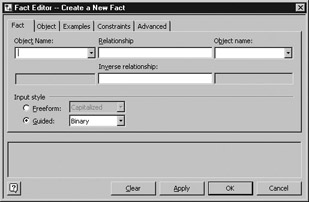
Click the Business Rules pane to give the pane focus and press the F2 key. The following dialog box will be displayed:
-
To enter the first elementary fact, type Candidate in the first Object Name field.
-
Type has a into the Relationship field.
-
Type Name into the second Object Name field.
-
Click the Apply button. We have now added the first elementary fact to our diagram: “Candidate has a Name.”
-
Click the Object tab.
-
Change the type of the Name object to Value because Name is an attribute of the Candidate and not an object unto itself.
-
Click the Examples tab.
-
To add some sample data to this fact, which will help validate the fact later, type the value 1234 in the Candidate column and the value John Smith in the Name column.
-
Click the OK button to exit the dialog box.
-
Add each of the 12 remaining facts from the case study to the business rules list in a similar fashion.
-
Choose File | Save to save the changes to the diagram.
Step Two: Drawing a Conceptual Model
One of the cool things Visio can do with ORM models is draw an ORM diagram for you based on the facts and constraints you have entered. This will make things easier for us as we make our way through this case study.
Once we have established all the elementary facts during the first step of the CSDP, it is fairly easy to turn those facts into an ORM diagram for the second step. The process of establishing (and quality-checking) facts has actually established the list of entities contained in our database. In ORM, entities are represented by ovals, drawn with solid lines. For instance, the following illustration shows how three of our database entities will look inside an ORM diagram.
![]()
| Exam Watch | Inside an ORM diagram, the << symbol is used to represent a role that is meant to be read from right to left. This is done so that objects and values can be spaced more evenly inside a diagram. |
Values, which are the text strings or numbers inside our elementary facts, are represented by dotted-line ovals. The relationship verb (or role) connects two objects on the screen, as you can see in the following illustration. This image represents a binary fact, as represented by the two boxes connecting the object and the value.
![]()
Unary facts are drawn using only the object and its role, as you can see here:
![]()
To create the ORM diagram, you simply go through each of the facts identified in step one and add them to the diagram.
Excerise 5-3: Autogenerating an ORM Diagram in Visio for Enterprise Architects
In Exercise 5-2, we used the Business Rules pane to add an elementary fact to an ORM diagram in Visio. Once we have added all 13 facts established in this chapter’s case study, we are ready to generate a diagram. In this exercise, we will tell Visio to build an ORM diagram automatically based on the elementary facts.
-
Choose Start | All Programs and choose Microsoft Visio to start the application.
-
Choose File | Open and navigate to the ORM diagram you saved in the last exercise to open it.
-
Select all the elementary facts in the Business Rules pane by selecting the first fact using the mouse and then selecting to the last fact using the mouse while holding down the SHIFT key.
-
Drag the group of selected facts onto the blank drawing.
-
The resulting diagram, shown in the following illustration, is the ORM diagram defined by our 13 elementary facts.
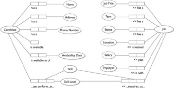
On The Job In Visio, the ORM diagrams that you create by dragging and dropping all the facts in one large group may not be organized on the page in the most readable manner. It is sometimes better to drag and drop each fact individually (or in smaller-sized groups) onto the page to get the diagram to look the way you would like it to look. Alternatively, you can move objects around the page manually after Visio has generated the diagram.
Step Three: Trimming the Conceptual Model
The third step of the CSDP process requires us to examine the basic entity types we have identified to see if any of them can be combined. In step three, we also need to examine the facts to see if any of them can be derived using arithmetic instead of having to be explicitly stated.
At first glance, our HGL employment agency case study does not appear to have any combinable entities. Following are the identities we have identified:
-
Candidate
-
Job
-
Skill
-
Skill Level
-
Availability Date
-
Type
-
Status
-
Employer
Two of those entities are very similar—you could potentially have the same person filling the roles of Candidate and Employer. That would occur if a person whose r sum were in your database (and presumably were not currently looking for work) also ran a small business that occasionally hired people; but since the candidate and the employer do not have very many properties in common and do not share the same relationships with other entities, it would not make sense to combine them into a single object.
For an example of when it makes sense to combine entities, let’s assume that fact numbers 4 and 13 were restated as follows:
| Fact Number | Description |
|---|---|
| 4 | Candidate 1234 can perform the Candidate Skill “C programming” at an expert Skill Level. |
| 13 | Job “T99” requires the Job Skill “VB .NET programmer” at an intermediate Skill Level. |
We could make the argument, if this were the case, that the Candidate Skill and Job Skill entities could potentially be combined into a single entity named Skill. Candidate Skill and Job Skill have enough in common that combining them simplifies the model instead of making it more complex, so it appears we were correct during the first step of the CSDP to define Skill as a single entity instead of two similar entities.
The second part of this step is to see if any of the facts can be derived by arithmetic instead of being facts on their own. None of the facts in our example so far have an arithmetic component, so we’re going to add an eighteenth fact in order to demonstrate this point:
| Fact Number | Description |
|---|---|
| 18 | Employer “Acme Health Labs” has available Jobs in quantity 5. |
Even though this statistic might be something that our system will have to keep track of, this value can be calculated simply by counting the number of jobs available with a particular employer. This saves us from having to store that information in the database separately. Since fact 18 can easily be derived using arithmetic, we shall safely remove it as a redundancy.
At the end of the third step, the data model for our case study has not changed from what it was at the end of step two.
Step Four: Adding Uniqueness Constraints and Checking Arity
The fourth step is to add uniqueness constraints to the diagram. Uniqueness constraints are a way to state that a particular value can occur at most once for a particular data field. You might think that certain properties can be called unique—Name, for instance—but a deeper examination would find that, in fact, it is entirely likely that two different candidates can share the same name; therefore, that field would not be considered unique. However, we could say that a candidate can have at most one name, so the candidate is unique to the name even though the name is not unique to the candidate.
The uniqueness of a particular set of values is represented in the ORM diagram as a bar across one or more roles, as in the following illustration. In this example, each Job object can have at most one Job Title value. Because a bar does not appear above the Job Title role, each Job Title can be repeated across several Jobs—that is, the title is not unique. In ER modeling, this is known as a zero-or-one-to-many relationship.
![]()
Uniqueness can occur between two unrelated entities or between an entity and an unrelated value. This is called external uniqueness. For instance, in our case study, we can say that in our database there is uniqueness between the candidate’s name and address. That is, although multiple candidates may live at a single address, each address will contain candidates with distinct names. There will not be two John Smiths living at a single address. If there are, they will have to be made distinct somehow—for example, with the addition of a middle initial or middle name.
External uniqueness is represented on an ORM diagram by a circle with a letter U inside, as you can see in the following illustration. This graphic depicts the fact that the candidates must have a name unique to that address in our database.

The second part of this step is checking for unnecessarily high arity counts. This step is important, particularly for ternary facts or facts with larger arity counts. Recall that a ternary fact is a fact that contains three objects. Let’s assume we had included the following fact in step one as fact 19:
| Fact Number | Description |
|---|---|
| 19 | The Candidate with Candidate ID 1234 currently has the Job Title “Programmer/Analyst” and is making an annual salary of $35,000. |
In step four, we need to evaluate whether this ternary fact should be split into two binary facts, as follows:
| Fact Number | Description |
|---|---|
| 20 | The Candidate with Candidate ID 1234 currently has the Job Title “Programmer/Analyst.” |
| 21 | The Candidate with Candidate ID 1234 is making an annual salary of $35,000. |
To decide if this fact needs to be split in two, we need only to ask ourselves if the Job Title and annual salary properties are dependent on each other. That is, do we lose any information by splitting the current job title and the current annual salary into two facts? In fact, we can see that we do not lose any information by splitting them into two facts, so if fact 19 were one of the facts required by our application, facts 20 and 21 would replace it.
Figure 5-2 shows how the ORM diagram from our case study looks with the uniqueness mark added.
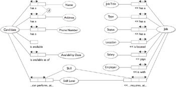
Figure 5-2: The updated diagram including uniqueness constraints
Step Five: Adding Mandatory Role Constraints and Checking for Logical Derivations
Step five of the CSDP requires that we add mandatory role constraints to our model. A mandatory role is like a mandatory field on a form. For instance, in our case study, we can say that all candidates must have a name. By stating this, we are indicating that the Name role is mandatory for the Candidate object. Likewise, we can state that a candidate may or may not have skills. Skill, therefore, would be an optional role for the Candidate object.
Mandatory roles are drawn using a dot attached to the object, as in the following example. The dot attached to the Job object in this illustration indicates that the Job Title value must be specified—it cannot be left empty or blank.
![]()
If an object must fill at least one of two or more roles, this is indicated with a dot inside a circle on the ORM diagram. For instance, in our case study example, a candidate must either be available or have an availability date on the system (as defined in facts 7 and 17).

If an object plays only one role in the system, then its role is mandatory by default and no mandatory constraint needs to be added to the diagram. For example, the Skill Level entity only has one role in the system—“Candidate can perform the Skill at Skill Level”—so even though Skill Level is obviously mandatory, it does not require a dot.
The second part of step five is to check for logical derivations. We already checked for arithmetic derivations in step four—to see if any of the facts could be derived using mathematics. Now we need to check to see if any of the facts can be derived using something other than arithmetic derivations. For instance, in our case study, we could ask whether the location of a job can be derived from the company that job is with. It might be safe to assume, for instance, that if a job were with Microsoft it would be located in Redmond, Washington; but, of course, many companies (including Microsoft) have more than one office location, so we cannot safely assume the location based on the client name.
There are other ways to derive one fact from another. For instance, let’s assume there were a number of years of experience associated with each candidate/skill combination, as shown here:
| Fact Number | Description |
|---|---|
| 21 | Candidate 1234 has experience of 5 years with Skill “C programming.” |
If this were true, it would be worth checking to see if there were a correlation between years of experience and skill level. It might be that the beginner level has less than two years of experience, the intermediate level has between two and five years, and the expert level has five or more years of experience. If the skill level can be logically derived from the years of experience, we would be able to get rid of the fact related to skill level in this example.
Because the case study was defined after step one, no logical derivations can be found. Figure 5-3 shows how the ORM diagram from our case study looks with the mandatory role dots added.
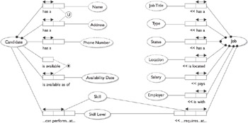
Figure 5-3: The updated diagram including mandatory role constraints
| If a fact can be derived using mathematics, such as a count or a total,... | Follow step 3 of the CSDP to remove it from the conceptual model. |
| If a fact can be derived using logic or a business rule,... | Follow step 5 of the CSDP to remove it from the conceptual model. |
Step Six: Adding Value, Set Comparison, and Subtyping Constraints
The sixth step of the conceptual database design is to add value, set comparison, and subtyping constraints to the ORM diagram. Value constraints list all the possible values for a value. For instance, the skill level can be either “beginner,” “intermediate,” or “expert,” and the job status can be “unfilled,” “pending,” “filled,” or “cancelled.” The value constraints are added to the ORM diagram as an enumerated list of strings, enclosed in curly brackets, such as {“unfilled”, “pending”, “filled”, “cancelled”}.
Set comparison constraints allow you to define a rule whereby in order for an object to fill one role, it must first fill another. For instance, in order for a person to be available for work, that individual must also be legally eligible to work. The set of available candidates is a subset of the set of legally eligible candidates. The set comparison is represented graphically using the symbol, as shown in the following illustration. This diagram depicts the statement, “A candidate can’t be flagged as available if that candidate is not already flagged as legally allowed to work.”

Subtyping involves inspecting each optional role to see if only a well-defined subtype of the object performs that role. For instance, only full-time jobs pay an annual salary. Contracts and part-time jobs pay an hourly wage. Therefore, we might want to create three subtypes for the Job object: FullTimeJob, PartTimeJob, and ContractJob. Additionally, we can see that part-time jobs have additional properties other jobs do not, such as number of hours per week. Contracts have their own properties as well, such as contract end date.
On ORM diagrams, subtypes are drawn with an arrow pointing from the subtype to its parent type, as shown in the following illustration.
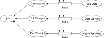
Figure 5-4 shows how the ORM diagram from our case study looks with the value constraints added.
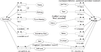
Figure 5-4: The updated diagram including new value constraints
Step Seven: Adding Other Constraints and Performing Final Checks
There are a handful of other constraints that can be added to ORM diagrams. For instance, take the example of the employee who manages other employees. We can add an irreflexive constraint to indicate that employees cannot manage themselves; or, if an employee must have a certain number of skills, we can add a frequency constraint to indicate the number of times that role must exist in the database.
The CSDP process ends with some final checks to ensure that our schema is complete. Essentially, this involves checking over each of the roles in the diagram to make sure there are no redundancies and that the original intent of the database is maintained. Once we are happy with the entities, properties, roles, and constraints defined, we’re done—the database schema has been defined.
Visio for Enterprise Architects does a great job of helping database designers build ORM diagrams. For those who prefer drawing these diagrams by hand, Visio also has the regular drag-and-drop template, which allows you the maximum flexibility when creating diagrams. As we said at the beginning of the chapter, these diagrams can be exported in ER format to make the transition from ER to ORM easier. If you have a large investment in ER diagrams for database documentation, that investment does not have to be thrown away.
Now that you have an understanding of designing a database schema using ORM, we can look at the entire application from the conceptual point of view. The next chapter covers the conceptual design component of designing software in Microsoft .NET. We will also discuss the types of technical architecture that can be used in our solution, as well as the various means for validating our conceptual design.
| If a value can only occur at most one time in a data set,... | Apply a uniqueness constraint. |
| If a value must be present for every data record,... | Apply a mandatory constraint. |
| If a value must contain one of a set number of values,... | Apply a value constraint. |
EAN: 2147483647
Pages: 94