Calling Search Spaces and Partitions
This section discusses calling search spaces and partitions, a powerful but complex pair of mechanisms by which you can customize dialing restrictions for individual users. Calling search spaces and partitions allow you to administer such policies as routing by geographic location, routing for multiple tenants, and routing by security level of calling user.
The need to configure routing by geographic location occurs because of the nature of VoIP telephony. In an IP network, the location of the endpoints is largely irrelevant. A computer in a cubicle in the United States can connect to a computer in the United Kingdom as easily as it can connect to the computer in the neighboring cubicle. Furthermore, large enterprises can and do interconnect all of their geographically distributed sites so that everyone can access the same data applications. As a result, CallManager must take into account the fact that two phones controlled by one CallManager may reside in different locations. When one user dials an emergency number, the emergency call may need to route to a different gateway than when a different user dials the same emergency number. In addition, having IP connectivity among all of your enterprise's sites permits you to take advantage of toll restriction. Toll restriction is a process by which your enterprise can save money by avoiding routing calls over the PSTN when the endpoints involved in the call are connected by your private data network.
The need to configure routing by organization occurs because you can control devices owned by different companies or departments within a single company using a single CallManager. Perhaps you are an engineer, and your neighbor is in marketing. Because an engineer is likely to require complex computer software packages on the computer, and a marketer is more likely to run standard software, different IS departments might maintain your computers. Customizing call routing by the organization to which a user belongs allows you to set up a common help desk number that users can call when they encounter computer difficulties, but to route those calls to different departments. Taken to an extreme, one CallManager could serve members of completely different companies with completely independent route plans, a configuration termed multitenant or IP Centrex.
The need to configure routing by security level of calling user occurs because you need to prevent unauthorized users from placing calls that cost your enterprise money. For example, executives within your enterprise might need to make international calls, while office personnel within your enterprise need to be limited to only national numbers, and lobby phones need to be limited to emergency services and internal extensions.
This section contains the following subsections:
- "Calling Search Space and Partitions Analogy" presents an analogy that might clarify how calling search spaces and partitions work.
- "Calling Search Space and Partition Operation" describes the way in which calling search spaces and partitions work. It also presents a simple example and then discusses some unusual aspects of calling search spaces and partitions.
Calling Search Space and Partitions Analogy
Calling search spaces and partitions allow you to configure individualized call routing, because they restrict the route patterns that CallManager can access on behalf of a calling user. When seeking a match for a calling user's dialed number, CallManager restricts its search to only those route patterns that reside in the partitions that are listed in the calling user's calling search space. The following example serves as an analogy that might help explain calling search spaces and partitions.
Figure 2-24 depicts two people, Rita and Dave. Rita wants to call Dave.
Figure 2-24. Calling Search Space and Partition Analogy
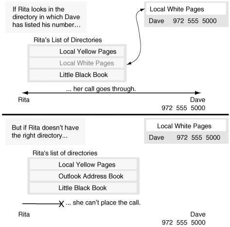
For Dave to be called, he must have a phone number. Furthermore, if he wants people to call him, he needs to list his number in a directory. Assume Dave lists his number in the local white pages. (Although in real life, Dave could list his number in multiple directories, for purposes of this analogy, he can choose only one directory in which to list his number.) To call Dave, Rita needs to know his number. Rita looks for Dave's number by searching through any directories to which she has access.
If she owns the local yellow pages, her little black book, and a copy of the local white pages, when she looks for Dave's number, she finds it in the local white pages. Knowing it, she can dial it, and Dave's phone rings. Lacking the white pages, however, she is unable to call Dave, because none of the directories she owns lists his number.
The directory in which Dave lists his number is equivalent to the partition in which you list a route pattern, while the list of directories that Rita looks through to find Dave's number is equivalent to the calling search space you assign to calling devices.
Using calling search spaces and partitions allows you to give each device in your network a different picture of the routing landscape. As a result, you can configure your network so that when different users dial the same digit string, CallManager selects different destinations. This ability allows you to solve problems when your users are geographically dispersed, have different calling privileges, and belong to different organizations with independent dial plans. The section "Case Studies" discusses some complex configurations that use calling search spaces and partitions, but first, the section "Calling Search Space and Partition Operation" describes the basics.
Calling Search Space and Partition Operation
Partitions divide the set of all route patterns into subsets of equally reachable destinations. Equally reachable means that a user who can call any single member of the subset can call all members of the subset.
A partition is simply a name you choose to identify a subset. For example, if you need a subset to contain the directory numbers of all user devices in your company (for example, Company ABC), you can create a partition named after your company ("ABC") and then assign the partition to all directory numbers in your system. Any user who can call one of the stations in partition "ABC" can call any of the stations in partition "ABC."
Devices to which you do not assign a partition belong to the or null partition. Assigning a route pattern to the null partition makes its address visible to every device in the system.
A partition is an attribute of an address. It belongs to called entities; it has no bearing on who a device can call. Membership in a partition does not automatically mean that a device can call other devices in the partition. The list of partitions in a device's calling search space is the sole dictator of who it can call.
Partition assignment exists virtually everywhere in CallManager where you assign an address: route patterns, translation patterns, directory numbers, in addition to Meet-Me conference numbers, call park numbers, and so on.
Assigning partitions to addresses is not sufficient in itself to allow you to impose dialing restrictions. Partitions merely divide the global address space into meaningful subsets. After assigning partitions, you must assign calling search spaces to your calling users.
A calling search space is nothing more than an ordered list of partitions. A device's calling search space determines the partitions in which it is allowed to look when resolving dialed digit strings to called destinations. Calling search spaces implicitly include the null partition as the last (and thus lowest priority) partition in the list.
Calling search spaces belong to calling entities. Naturally, this includes stations and gateways. However, it also includes the CTI interface, which can redirect incoming calls, and call forward, which originates new calls on behalf of a called destination.
Calling search spaces are ordered. However, when analyzing a dialed digit string, the call routing component looks through every partition in the calling search space (including the null partition). Even if the call routing component finds a match in the middle of the routing analysis, closest match routing rules (see the section "Example 2Closest Match Routing") apply. CallManager seeks the closest match among all the partitions listed, even if the closest match exists in the last partition in a calling search space.
For example, assume that route pattern 1XXX exists in partition A, and the route pattern 1000 exists in partition B. A device with a calling search space that starts with partition A and ends with partition B dials 1000. CallManager extends the call to the device with route pattern 1000, even though 1XXX both matches the dialed number and precedes partition B in the device's calling search space.
Calling search space order comes into play only if two or more partitions contain addresses that match equally closely. In such a case, the call routing component selects the destination from the first partition among the partitions containing a match for the dialed digit string. To put it another way, CallManager uses the order of partitions in a calling search space only to break ties.
The rest of this subsection covers the following topics:
- "Calling Search Space and Partitions Example" provides a simple example to show how to use calling search spaces and partitions.
- "Calling Search Spaces on Line and on Station" explains why both line and station have calling search space fields.
- "Call Forwarding Calling Search Spaces" describes how the different calling search spaces associated with call forwarding operate.
- "Message Waiting Indicator" describes how CallManager uses calling search spaces and partitions to set voice message waiting indicators.
- "Time-of-Day Routing" describes the use of partitions to implement time-of-day call routing.
- "QSIG Calling Search Spaces" describes how CallManager uses calling search spaces to handle the QSIG features of path replacement, call completion, and call forward by rerouting.
Calling Search Space and Partitions Example
A multiple-tenant installation provides the clearest illustration of how calling search spaces and partitions work. In a multiple-tenant environment, one CallManager or CallManager cluster that a single service provider administers serves two independent organizations, each with its own numbering plan. The numbering ranges for each organization may be completely isolated from each other.
Figure 2-25 presents a simple multiple-tenant configuration that demonstrates two calls, one that succeeds and one that fails. Company ABC has a station with directory number 1000 and a station with directory number 2000. Company XYZ has a station with directory number 1000 and a station with directory number 3000. Users in Company ABC can call each other but not the users in Company XYZ and vice versa.
Figure 2-25. Multiple-Tenant Example
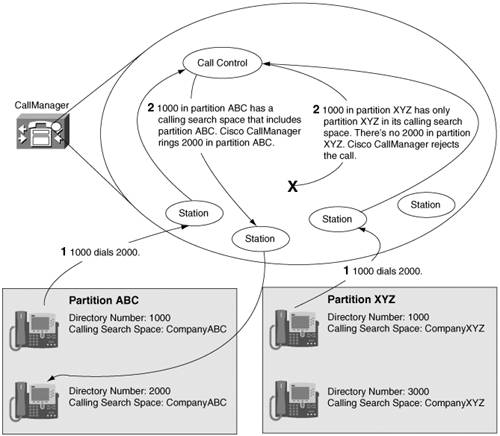
In CallManager, no address is complete unless it consists of both a route pattern and a partition. (Keep in mind that all destinationsdirectory numbers, call park numbers, Meet-Me conference numbersare route patterns.) The previous paragraph, therefore, commits an egregious error in omitting that the partition is associated with the directory numbers. If the partition is equivalent to the directory in which one lists a number, it seems reasonable to list Company ABC's directory numbers in partition ABC and Company XYZ's directory numbers in partition XYZ. Above all, the stations with directory number 1000 must be listed in different partitions. If you list them in the same directory, they represent a shared line appearance.
Simply setting up the partitions is not enough to complete the routing setup. You must assign each station a calling search space. Because the stations in Company ABC must be able to call other stations in Company ABC, assign them a calling search space that includes partition ABC but not partition XYZ. Assign stations in Company XYZ a calling search space that includes partition XYZ but not ABC.
When the user at directory number 2000 dials 1000, the call routing component looks through the partitions listed in the calling search space to find a match. Because directory number 2000's calling search space contains only partition ABC, the call routing component finds the directory number 1000 in Company ABC. If, on the other hand, the user dials 3000, the call routing component does not find it, and the caller hears reorder tone.
Figure 2-26 presents a modification of the multiple-tenant example. Once again, it shows two calls. In this example, users in Company ABC can call not only other Company ABC users, but also Company XYZ users. Users in Company XYZ can still call only Company XYZ users.
Figure 2-26. Revised Multiple-Tenant Example
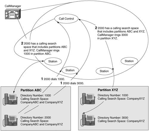
To accomplish this task, the calling search space that users in Company ABC use includes both partition ABC and XYZ. Assume partition ABC is first in the calling search space.
Now, when the user at directory number 2000 dials 1000, the call routing component finds matching route patterns in both partition ABC and XYZ. Because the matches are equal, CallManager still routes the call to the user at directory number 1000 in Company ABC. However, if the user at directory number 2000 dials 3000, the call routing component finds the matching route pattern in partition XYZ and offers a call to the associated destination.
Figure 2-27 revises the example yet again to illustrate closest match routing. Again, the example shows two calls. Assume that the route pattern 3XXX provides Company ABC users access to a PBX through a voice gateway. Because only Company ABC users can dial to the PBX, the route pattern 3XXX is listed in partition ABC.
Figure 2-27. Revised Multiple-Tenant Example
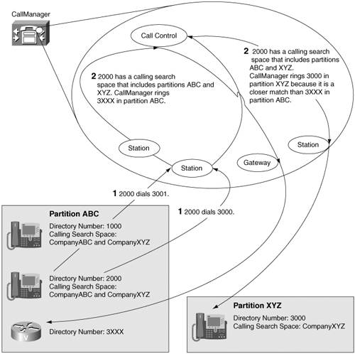
When the user dials directory number 3001, CallManager extends the call to the voice gateway. However, when the user at directory number 2000 dials 3000, the call routes to the user in Company XYZ instead of routing to the PBX, even though the caller's calling search space lists partition ABC before partition XYZ. This behavior occurs because CallManager searches through every listed partition when analyzing dialed digits. Regardless of the order of the partitions in a calling search space, CallManager always delivers a call to the device with the closest matching route pattern.
Calling Search Spaces on Line and on Station
A common question is "Why does a calling search space exist on both the Directory Number Configuration page and the Phone Configuration page, and which one should I configure?"
A calling search space exists on the Phone Configuration page so that different stations with the same line appearance can route differently. Because CallManager servers can serve stations that are in different Local Access and Transport Areas (LATA), CallManager must provide a mechanism for routing each station's calls differently. For example, emergency calls from a station in San Jose must route to the San Jose PSTN, even if the San Jose station shares a line appearance with a Dallas station (whose emergency calls must route to the Dallas PSTN).
A calling search space exists on the Directory Number Configuration page so that different line appearances on a station can route differently. The justification for this configuration is a little more strained. One application is for a security guard desk in a multiple-tenant installation. Because different tenants might have phones with identical directory numbers, the security desk needs to be able to place calls to any tenant. As the example in the section "Calling Search Space and Partitions Example" illustrates, calling search space order causes the call routing component to choose from among equal matches to a dialed digit string.
One approach for dealing with the problem is to give the security guard's phone multiple line appearances. When calling one tenant, the guard uses one line appearance; when calling the other, the guard uses the other. If the guard's calling search space was associated solely with the station, such a configuration still would not work. As a result, to have calls from a single station route differently, calling search spaces must also be associated with a line appearance.
If you configure calling search spaces for both a station and a line, CallManager uses both calling search spaces to analyze a dialed digit string. The calling search space associated with the line takes priority when equal matches exist in the station and line calling search spaces.
Call Forwarding Calling Search Spaces
The call forwarding search spaces defined on the Directory Number Configuration page have some interesting effects. The Directory Number Configuration page defines seven fields that let you set calling search spaces associated with call forwarding:
- Call Forward All Calling Search Space
- Call Forward Busy Calling Search Space (internal and external)
- Call Forward No Answer Calling Search Space (internal and external)
- Call Forward No Coverage Calling Search Space (internal and external)
Using these fields, you can forward a user's calls to destinations the user could not normally call directly. Conversely, you can prevent the user from forwarding calls to certain destinations, even if the user could normally dial such destinations directly. For instance, using call forwarding search spaces, you can prevent a user from forwarding a phone to long distance or international destinations. This sort of configuration prevents a toll-fraud scenario, by which a user call forwards a phone to an international destination and then calls the office phone from home to make a free (to the user but not to your enterprise) long distance call.
The call forward busy and call forward no answer calling search spaces you define always take effect. In particular, when you set the call forward busy or call forward no answer calling search space to , CallManager grants the forwarding phone access to only the null partition. The call forward all calling search space operates differently.
If you define a call forward all calling search space other than , it always takes effect. However, if you leave the call forward all calling search space set to , when the user forwards the phone from the phone itself or from the user configuration pages, the calling search space that CallManager uses for the call forward is the calling search space that the user uses when placing direct calls.
This behavior allows a user who shares line appearances in different geographical locations (perhaps because the user travels regularly from one location to the other) to forward the phone according to the appropriate geographic location.
While the calling search spaces associated with the seven different call forwarding settings define which partitions CallManager should use to resolve the forward destination, you can specify the actual forward destination in one of two fields:
- The Coverage/Destination field is the more straightforward. If you enter digit strings in these fields and do not check the associated Voice Mail check box, CallManager resolves these digits against the corresponding call forward calling search space to determine which destination to route the call to.
- CallManager, however, also allows you to specifically forward the call to voice mail by checking the Voice Mail check box for a particular forwarding type. The following section, which discusses CallManager's treatment of voice mail, provides more information about this setting.
Calling Search Spaces Interaction with Unified Messaging Systems
Unified messaging systems provide a place where you can centralize your enterprise's data communications. At a minimum, such systems handle the integration of voice mail, e-mail, and fax information. CallManager's direct interaction with such systems is in the voice mail domain. CallManager interacts with unified messaging systems using the following types of interfaces:
- SCCP Used by unified messaging systems such as Cisco Unity
- Analog gateways managed through a Simple Message Desk Interface (SMDI) Used by most legacy voice mail systems
- QSIG Used by PBXs or other CallManagers that host a voice mail system and that connect to CallManager over a QSIG digital interface
- JTAPI Used by voice mail systems that connect to CallManager using an application interface
All types of unified messaging systems interact with CallManager in essentially the same manner. That is, the nature of the communication between the systems can be boiled down to the following dialog:
- When CallManager offers a call to a unified messaging system, the unified messaging system needs to know to which voice mailbox to redirect the call.
- When a caller has left a message in a voice mailbox, or when a voice mail user deletes all pending messages, CallManager needs to receive a notification from the unified messaging system about which device to notify about the status of pending messages.
The lingua franca of this communication is through directory numbers (from CallManager's point of view) or mailbox numbers (from the unified messaging system's point of view). That is, CallManager delivers a call to a unified messaging system, CallManager provides a mailbox number, and when the unified messaging system delivers a voice mail notification message, the unified messaging system delivers the directory number of the device that should be notified of pending messages. Whether you call it a directory number or a mailbox number, the information the two systems share is simply a number.
CallManager, however, does not deal in bare numbers. Every route pattern and directory number in CallManager's configuration resides in a partition (even if that partition is set to ), and when routing calls, CallManager uses the calling search space of the calling device.
Unified messaging systems do not understand calling search spaces and partitions, so CallManager must maintain a calling search space on behalf of the unified messaging system to properly route the message waiting indication. Furthermore, when CallManager has overlapping extensions, as in the case of multitenant installations, it is sometimes necessary to perform number translation to ensure both that messages from two different users do not end up in the same voice mailbox, and that CallManager delivers message waiting notifications to the correct users.
This section covers the following topics:
- "About Cisco Messaging Interface (CMI)" discusses one method that CallManager uses to integrate with voice messaging systems.
- "About Non-SMDI-Based Unified Messaging Systems" discusses another method that CallManager uses to integrate with voice messaging systems.
- "Delivering the Correct Mailbox Number to Unified Messaging" discusses CallManager settings that inform a voice messaging system about which voice messaging box should receive a voice message.
- "Message Waiting Indicator" discusses the CallManager settings that permit a voice messaging system to set message waiting indicators for IP Phones.
About Cisco Messaging Interface (CMI)
Many traditional unified messaging systems connect to CallManager by SMDI. SMDI is a standard protocol specifically designed to permit different telephone systems to integrate with voice mail systems. It uses an RS-232 interface between a telephone system and a voice mail system to communicate information between the systems.
SMDI provides three types of messages:
- Messages about calls from the telephone system to the voice mail system. These messages include the voice messaging box number, whether the call is direct or forwarded, and trunk interface over which the telephone system presents the call.
- Message waiting indications from the voice mail system to the telephone system.
- Error messages between the systems.
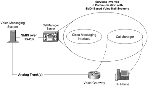
CallManager connects to voice messaging systems with the help of the CMI service. The CMI service observes calls from CallManager to a voice mail system and manages the RS-232 SMDI interface between CallManager and the legacy voice mail system.
Figure 2-28 presents a typical connection between CMI and CallManager. When CallManager offers a call to the gateway to the voice mail system, CMI sends an SMDI message to the voice mail system that tells the voice mail system to associate the incoming call with a particular voice messaging box. When the calling user leaves a voice message, the voice mail system, in turn, sends an SMDI message to CMI, which tells CallManager to set the message waiting indicator on the appropriate phone.
Figure 2-28. SMDI Interaction Between CallManager and a Legacy Voice Mail System
CMI has several service parameters that must be set properly in order to function. CallManager user documentation describes these parameters, but Table 2-51 summarizes the ones that are inextricably intertwined with CallManager call routing settings.
|
CMI Service Parameter |
Description |
|---|---|
|
Message Waiting Indicator Calling Search Space |
The calling search space that CMI should use when telling CallManager to set a phone's message waiting indicator |
|
Voice Mail DN |
The directory number (or route pattern) associated with the voice mail system |
|
Voice Mail Partition |
The partition associated with the voice mail system |
About Non-SMDI-Based Unified Messaging Systems
Unified messaging systems that use SCCP or H.323 interact directly with CallManager. They do not rely on the CMI service or an RS-232 connection. Rather, when CallManager offers a call to these systems, the call setup message directly provides them with the information that they need to deliver the voice message.
When non-RS-232-based voice messaging systems need to set a message waiting indicator for a particular phone, they do it in a rather unusual manner. CallManager includes a message waiting feature that unified message systems can access by dialing numbers you configure in CallManager Administration (Feature > Voice Mail > Message Waiting).
When a voice messaging system needs to set a message waiting indicator, it calls either the message waiting on or message waiting off directory number and provides the directory number of the phone whose message waiting indicator should change as the calling number.
Message waiting numbers are patterns like other dialable addresses and thus belong in partitions. When configuring a message waiting number, the calling search space of the calling voice mail system needs to contain the partition of the message waiting on or message waiting off number.
Message waiting numbers have their own search spaces. CallManager uses the calling search space that you associate with the message waiting numbers to locate the Cisco IP Phones for which you want to leave a message waiting indicator; therefore, the calling search space for the message waiting number should contain the partition of your IP Phones (or of a translation pattern that selects your IP Phonessee the section "Message Waiting Indicator").
CallManager service parameters control several settings related to voice messaging. Table 2-52 lists these settings.
|
CallManager Service Parameter |
Description |
|---|---|
|
Multiple Tenant MWI Modes |
When set to True, this setting permits you to use translation patterns to convert voice messaging box numbers back into directory numbers when a voice mail system issues a command to set a message waiting indicator. It defaults to False. The section "Message waiting Indicator" explains this function in more detail. |
Delivering the Correct Mailbox Number to Unified Messaging
In CallManager 4.1, you configure voice mail information for an endpoint by building a voice mail profile (Feature > Voice Mail > Voice Mail Profile) and associating it with the endpoint on the Directory Number Configuration page.
Voice mail profiles consist of several pieces of information:
- A voice mail pilot describes the primary address to which you have associated voice mail. Voice mail pilots contain two primary pieces of information, a voice mail pilot number and a calling search space. The voice mail pilot number represents the pattern that you have assigned to the voice mail system, and the calling search space includes the partition that you have assigned to the pattern that includes the voice mail system.
The voice mail pilot can represent a variety of destinations. For instance, with QSIG-based voice mail, the pilot number can represent but a single gateway. With SCCP-based voice mail systems such as Cisco Unity, this pilot number can represent a hunt list containing the individual Unity voice mail ports. With legacy voice mail systems connected via Cisco MGCP gateways, this pilot number can point to a route list that selects one or more MGCP gateways that connect to the voice mail system.
When you configure a voice mail pilot, you are not actually defining the routing construct needed to route the call to the actual voice mail system. For example, if you have Cisco Unity voice mail, you must still configure a hunt list containing individual voice mail ports.
Instead, consider the voice mail pilot as a call forwarding destination; when CallManager determines that the call must go to voice mail, it directs the call to the number you configure using the associated calling search space. For the call to be processed properly, you must configure the destination (a hunt pilot or route pattern) that will handle the call).
In fact, the voice mail pilot is very much like a forwarding destination. When you check the Voice Mail check box by the Forward All, Forward No Answer Internal, Forward No Answer External, Forward Busy Internal, Forward Busy External, Forward No Coverage Internal, and Forward No Coverage External settings, the destination to which CallManager forwards the call and the calling search space that CallManager uses to forward the call is not that on the Directory Number Configuration page. Instead, the destination is the voice mail pilot and voice mail calling search space you configure in the voice mail profile assigned to the line.
CallManager also uses the voice mail pilot as the target called when IP Phone users press their messages button.
- A voice mailbox mask, which CallManager combines with the directory number with which you have associated the voice mail profile. For instance, if you configure a voice mailbox mask of 972813XXXX in a profile, when you associate the voice mail profile with directory number 5123, CallManager provides the voice mailbox number 9728135123 to the voice mail system. If you do not specify a voice mailbox mask, CallManager simply provides the directory number as the voice mailbox number.
Not all unified messaging systems handle the voice message box number. The following list describes how CallManager manages the voice message box for different types of unified messaging systems:
- SCCP Cisco Unity connects to CallManager using the Skinny Client Control Protocol (SCCP). When CallManager delivers a call to Cisco Unity, it provides both the directory number and voice message box of the phone that received the call. Currently, Cisco Unity determines in which voice message box to leave the caller's message based on the directory number that CallManager provides.
- H.323 H.323 provides information about the destination into which a unified messaging system should leave voice mail using the redirecting number information element.
Incidentally, CallManager sets up the redirecting number information element for calls across digital gateways using the same logic. If you connect CallManager to another telephone system with a digital interface, and the other system manages the unified messaging for your enterprise, this behavior can affect the voice message box that the unified messaging receives.
For instance, if phone 1000 calls phone 2000 controlled by CallManager, and CallManager subsequently forwards the call to the unified messaging system on the other telephone system, the redirecting number information element tells the other system that the call has previously been forwarded so that the voice messaging system can deliver any voice message to the correct voice message box. For the redirecting number, CallManager uses the voice messaging box you have configured for phone 2000, or 2000 if you have not configured a voice message box.
- Analog gateways connected with CMI and SMDI CMI always uses the masked voice mailbox you configure when informing a voice messaging system about a call.
- Voice mail systems hosted by other PBXs that support QSIG interfaces CallManager, as part of call forwarding or call transfers, communicates any configured voice mailbox to an attached PBX using application protocol data units (APDU) when forwarding takes effect. If you have not configured any voice mailbox for the forwarded phone, CallManager instead communicates the directory number of the forwarded phone.
Voice mail profiles allow you to deal with multiple-tenant configurations, because voice messaging systems do not understand calling search spaces or partitions. Without the voice message box information, CallManager can provide only the directory number of a called phone to a voice messaging system.
In a multiple-tenant configuration, two users may have the same directory number. CallManager does not provide partition information to voice messaging systems, so how can these systems decide which voice message box to deliver the voice mail message to?
They cannot. Therefore, by providing voice mail profiles, CallManager permits you to map duplicate directory numbers to unique ones (for example, the external numbers by which users in the PSTN call your enterprise).
Message Waiting Indicator
When a message is left for a user in a voice messaging system, the system tells CallManager to turn on the message waiting indicator for the user by one of the following methods:
- The voice messaging system sends an SMDI command to CMI containing the voice message box that received a voice message to CMI.
- The voice messaging system calls CallManager's message waiting on and off numbers and provides as the calling number the voice message box of the phone whose message waiting indicator must be changed.
- The voice messaging system, hosted on another PBX or CallManager, delivers a message waiting indicator to the attached PBX or CallManager, which forwards a QSIG mwActivate APDU to the CallManager node that actually hosts the phone whose indicator must be lit.
CallManager uses the number that the voice message box provides and the calling search space parameter associated with the voice mail system to locate the phone whose message waiting indicator must be changed.
For the message waiting on and off numbers, configuration requires two steps. On the voice mail port that you have configured to handle the message waiting indicator command from the voice mail system, you must configure a calling search space that contains the partition that contains the Message Waiting On and Message Waiting Off numbers. The calling search space CallManager uses for this lookup is the calling search space you configure on the voice mail port or, for CMI, the CMI service parameter Message Waiting Indicator Calling Search Space.
Upon receiving the command to light or extinguish the message waiting lamp, the Message Waiting feature needs to locate the directory number whose lamp needs to be lit or extinguished. The calling search space CallManager uses for this lookup is the calling search space you configure under the Message Waiting Configuration page.
When the voice message box and directory number are the same, this lookup locates the number of the appropriate phone. But when the voice message boxes and the directory numbers of your phones differ, as is usually the case in multitenant installations, you must use translation patterns to direct the message waiting indicator to the correct phone. Using translation patterns for this purpose requires that you set the CallManager service parameter Multiple Tenant MWI Modes to True. Figure 2-29 shows the behavior that occurs when a voice messaging system attempts to set the message waiting indicator for the phone with voice message box 9725551212. It depicts a scenario that uses the message waiting on number. The same configuration works for the SMDI method of setting the message waiting indicator.
Figure 2-29. Transforming Voice Messaging Box Numbers to Set Message Waiting Indicators
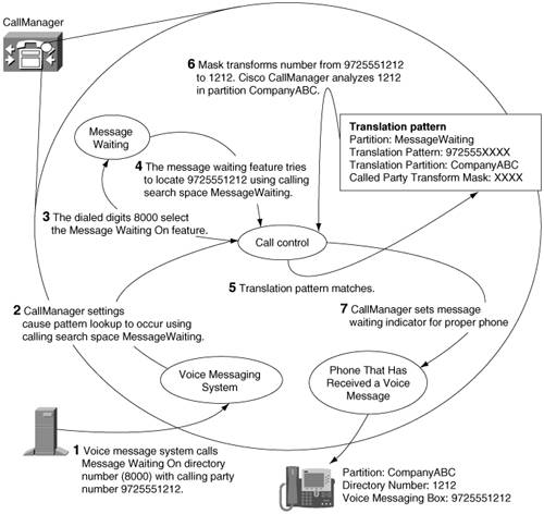
The example relies on the provision of the route and translation patterns in Table 2-53.
|
Configured Route and Translation Patterns |
Comments |
|---|---|
|
Partition: MessageWaiting Translation pattern: 972813XXXX Translation calling search space: CompanyABC Called party transformation mask: XXXX |
Translation calling search space CompanyABC contains partition CompanyABC. |
|
Partition: CompanyABC Route pattern: 1212 |
1212 is a phone with directory number 1212. |
When a voice messaging system calls the message waiting on number, CallManager performs the following steps:
|
Step 1. |
The voice messaging system calls CallManager's message waiting on directory number (8000) and specifies as the calling number 9725551212: the voice message box of the phone whose message waiting indicator CallManager must set. |
|
Step 2. |
The message waiting feature takes the information about the calling device (the calling search space and calling party number) and asks the call routing component of CallManager to look up the device. You can think of this process as the message waiting feature placing a special message-waiting- indicator call in which the calling party information that the voice messaging system provides becomes the called party information for setting the message waiting indicator. |
|
Step 3. |
The lookup matches the translation pattern 972555XXXX, because the calling party number9725551212becomes the called party number for the message-waiting-indicator call. CallManager applies the called party transformation mask XXXX to the number 972555XXXX to convert the called number to 1212. |
|
Step 4. |
CallManager uses the resulting number, 1212, as the input for another analysis attempt. The calling search space CallManager uses for the analysis attempt is the calling search space of the translation pattern, Company ABC. This attempt matches the phone with directory number 1212. CallManager sets the message waiting indicator of the phone with dialed digits of 1212. |
Time-of-Day Routing
CallManager 4.1 allows you to associate schedules with partitions. These schedules describe when a partition is active. Patterns that you place in active partitions can be routed to by CallManager, but when a partition becomes inactive, the patterns in that partition become "invisible," and calls no longer route to those partitions.
Setting up time-of-day routing is a three-step process:
|
Step 1. |
Define a set of time periods. A time period is simply a persistent or recurring time duration. You configure time periods in the Time Period Configuration page (Route Plan > Class Of Control > Time Period). |
|
Step 2. |
Arrange time periods into a time schedule. A time schedule is a more complex arrangement of time periods. For instance you might arrange a time schedule that includes the following:
|
|
Step 3. |
Associate a time schedule with a partition (Route Plan > Class Of Control > Partition). When you assign a time schedule, you have two options:
|
When a partition becomes unavailable due to a time zone transition, the call routing component of CallManager routes the call as if the patterns in the partition didn't even exist. This means that unless you configure some alternate route, callers hear reorder.
Sometimes, instead of blocking the call, you might want to route the call differently. For instance, you might want to explicitly permit all outside calls during the hours of 08:00 to 17:00, but prompt users for a forced authorization code after normal working hours.
In this case, you must configure two patterns, in different partitions, with different time schedules attached. For instance, to prompt for a forced account code after normal working hours, you configure the following:
- One time period called Workdays defining Mondays through Fridays, 08:00 to 17:00.
- One time schedule called WorkHours containing time period Workdays.
- One time period called BeforeHours defining Mondays through Fridays, 00:00 to 08:00.
- One time period called AfterHours defining Mondays through Fridays 17:00 to 24:00.
- One time period called Weekends defining Saturdays and Sundays, all day.
- One time schedule called NonWorkHours containing time periods BeforeHours, AfterHours, and Weekends.
- One partition called DuringHoursOutsideCalls containing the patterns that your enterprise uses to reach PSTN gateways. With this partition, you associate the caller-based time schedule WorkHours.
- Another partition called NotDuringHoursOutsideCalls containing copies of the patterns that your enterprise uses to reach PSTN gateways. Unlike the standard route patterns, however, check the Requires Forced Authorization Code check box. (See "Forced Authorization Codes and Client Matter Codes" for more information about configuring Forced Authorization Codes.)
During work hours, partition DuringHoursOutsideCalls will be active. If a caller were to dial an outside number such as 9 1 214 555 1212, it would find its match in partition DuringHoursOutsideCalls and route to your enterprise's PSTN gateways.
At 17:00 based on the caller's time zone, partition DuringHoursOutsideCalls becomes inactive, but, simultaneously, partition NotDuringHoursOutsideCalls becomes active. Now number 9 1 214 555 1212 matches the pattern in the latter partition, and CallManager prompts for an account code.
QSIG Calling Search Spaces
QSIG is a protocol designed to foster feature transparency between PBXs. Chapter 4 discusses QSIG in more detail, but certain QSIG features have call routing implications.
Traditional telephony features operate via the progressive extension of call legs. For instance, if a phone on PBX 1 calls a forwarded phone on PBX 2, PBX 2 traditionally affects the call forward by simply further extending the call in the forward direction. If, say, the forward destination is an extension on PBX 1, this approach creates a hairpin. Traditional call forwarding generates one call leg from PBX 1 to PBX 2 for the original call, which turns around and heads back to PBX 1 to reach the call forwarding target.
QSIG changes this dynamic by allowing PBX 2 to issue a command to PBX 1 to cause the call forwarding to be effected from PBX 1's point of view. This approach eliminates the hairpin, but it has call routing effectsCallManager's call routing constructs are always concerned about routing calls forward. How do backward routing messages such as QSIG impact it?
The following subsections discuss QSIG features that perform routing-related activities.
- "Call Forward by Rerouting" discusses the QSIG forward by rerouting feature, which allows you to prevent signaling hairpins from occurring when calls forward from one PBX to another.
- "Path Replacement" discusses the QSIG path replacement feature, which allows you to remove hairpins after they develop.
Call Forward by Rerouting
Call forward by rerouting is a QSIG feature that allows you to optimize the call signaling path when a call from CallManager to a PBX forwards to some other destination or when a call from a PBX to CallManager forwards somewhere, as long as CallManager and the PBX are connected via a QSIG gateway.
By default, CallManager operates according to the QSIG forward switch model. The QSIG forward switch model is nothing other than just a traditional telephony call forwarding model where the forwarding PBX extends new call legs toward the call forward destination. The QSIG forward switch model defines QSIG messages that can allow the caller to see the identity of the new ringing destination and the called party to see that the call has been forwarded.
The forward switch model is reliable and trustworthy, but it has the drawback of creating nonoptimized signaling paths. This can most easily be seen when considering the case where a call from one PBX crosses a circuit to another PBX, which forwards the callback to the first PBX. This model creates a signaling hairpin and consumes two circuits between the PBX, even though the final call between caller and forward target need not use any circuits at all. (When the connection between the PBX and CallManager is via an IP trunk, the consequences of call hairpinning are much less, because only the call signaling hairpinsVoIP media is always directly from calling endpoint to called endpoint.)
The forward by rerouting model changes the operation of the call forwarding feature so that rather than the forwarding PBX extending a call in the forward direction, call forward sends a message along the original circuit to the calling PBX and asks it just to call the call forward target directly.
In uniform enterprise numbering plans, this doesn't cause a problem. If you are using route codes to get from PBX to PBX, however, forwarded calls might fail. This failure can occur when the number that the forward target uses to reach the forward destination differs from the number that the caller uses to reach the forward destination.
An example that can demonstrate this problem follows. Alice is at 1000 and is served by PBX 1. Bob is at 2000 and is served by PBX 2. Carol is at 3000 also is at PBX 2. Assume that the enterprise route plan is set up so that when PBX 1 calls PBX 2, users at PBX 1 must prefix the called extension number with 888.
When Bob forwards his phone to Carol, Bob naturally enters the number that he would use to dial Carol3000. However, if QSIG forward by rerouting triggers, then when Bob's phone forwards, the numbering plan that the forward destination (3000) is resolved against isn't that of PBX 2. It's that of PBX 1, because the forward by rerouting feature is requesting PBX 1 to dial the destination. PBX 1 doesn't have access to the numbering plan of PBX 2.
However, PBX 1 can't reach Carol's phone using the digits 3000PBX 1 reaches Carol's phone using the digits 8883000. A call that would route via forward switch is dropped when forwarding by rerouting.
The previous example, although a good demonstration of the core problem, doesn't specifically affect CallManager. Before CallManager requests a calling PBX to attempt call forward by rerouting, it screens the forward destination that is configured. If CallManager decides that the forward destination is managed locally, CallManager uses the switch model for call forwarding, because any reroute request wouldn't optimize the path anywayit would just route back to CallManager.
Although CallManager is safe from the preceding example, it's not hard to construct cases where CallManager would not be able to detect, much less prevent, the problem. The core problem occurs any time the forwarding party points to a destination that the calling party would reach with a different dial string.
This chapter has stated several times that CallManager can't process dialed digits without having a calling search space against which to resolve the digits. When call forward by rerouting occurs, what calling search space does CallManager use?
CallManager's standard call forwarding uses the specific calling search space that is associated with the forwarding settings for the forwarded phone. Associating a specific call forwarding search space allows you to configure phones to permit a caller to directly dial outside destinations (using the line's and/or the device's calling search spaces) but not to forward calls to outside destinations (because of restrictions built in to the call forwarding calling search space). This configuration can prevent a toll-fraud scenario where users forward their phones to international destinations and then call their phones from home to get free (for them) international calling.
When different users in your organization have different permissions, call forwarding by rerouting can encounter problems. For instance, assume a lobby phone served by PBX 1 only has permissions to dial internal destinations. Your phone on PBX 2 has permissions to call internal and external destinations and, furthermore, can forward to external destinations. You step away from your desk and forward incoming calls to your cell phone.
If a client attempts to reach your desk phone from the lobby, normally CallManager uses your phone's calling search space to resolve the address and forwards the call to your cell phone. However, the QSIG protocol provides no way for PBX 2 to indicate calling search space information to PBX 1 and, furthermore, even if such a field existed, the calling search spaces of PBX 2 probably wouldn't make any sense to PBX 1. In short, when the user in PBX 2 forwarded the call, he implicitly did so under the assumption that the routing rules of PBX 2 applied. When rerouting occurs, the call operates using PBX 1's dial plan, which is clearly not the intent of the user served by PBX 2.
When CallManager receives a request to reroute a call, rather than use any of the permissions associated with the forwarded phone, CallManager simply uses the basic calling search space of the caller to resolve the forward target. In a dial plan with unified dialing and a standard permissions structure, using the basic calling search space of the caller can work; if your enterprise call routing plan is tricky, however, it's probably best to ensure that the service parameter Forward By Reroute Enabled is False (which, by default, it is).
Path Replacement
While call forward by rerouting is a feature that operates specifically for the call forwarding and that prevents hairpins from forming, path replacement is a feature that operates for call forwarding and transfer and that repairs signaling hairpins after they have already formed.
Path replacement allows you to specify a time delay using the service parameters Start Path Replacement Minimum Delay Time (sec) and Start Path Replacement Maximum Delay Time (sec). After either call forwarding or call transfer is invoked and completed and if QSIG path replacement is enabled (via the Path Replacement Enabled service parameter), CallManager waits for the minimum delay time to expire and then attempts to optimize the signaling path. If one of the endpoints involved in the transfer or call forward is served by a different PBX connected to CallManager by a QSIG trunk, this request can result in a call rerouting message being sent to that PBX (or CallManager, if QSIG tunneling over H.323 is being used).
Similarly, a transfer or call forwarding attempt on a different PBX connected via a QSIG trunk might result in CallManager receiving a path replacement request from the PBX.
The same issues that plague call forwarding by rerouting when the numbering plan isn't transparent also pose a problem for path replacement.
Path replacement takes a different tack on the problem. Because path replacement is just attempting to optimize the path from node to node after a connection has already been established, CallManager's implementation of path replacement requires that you assign each CallManager cluster its own unique identifier (configured using the Path Replacement PINX Id service parameter). When providing another system with a number to reroute to in order to replace the path, rather than provide the address of one of the endpoints, which could be subject to dial-plan transparency issues, CallManager provides the Path Replacement PINX Id instead. When issuing the replacement call, an attached PBX will puts, as the called address, the Path Replacement PINX Id.
In turn, however, you have to make sure that the PINX Id is a valid routable number, which might require you to provision some route patterns. For instance, imagine a configuration where CallManager cluster 1 is connected to CallManager cluster 2 over a QSIG gateway and where CallManager cluster 2 is connected to a PBX over a QSIG gateway. A call exists from CallManager cluster 1 to the PBX and the PBX asks for path replacement.
In response to the request, CallManager cluster 2 must provide a routable number to the PBX. For this purpose, CallManager uses the Path Replacement PINX Id. In CallManager cluster 2, by virtue of configuring the service parameter, you define the pattern, but it's possible that the replacement call will also route through Call Manager cluster 1. Unless you configure a specific route pattern on the cluster 1-to-cluster 2 link, the replacement call won't be able to reach cluster 1.
Typically, the worst thing that can happen when the routing for path replacement isn't completely configured is simply that the path won't be replaced. The endpoints will still converse via the unoptimized path and the call won't drop.
Cisco CallManager Architecture
- Cisco CallManager Architecture
- Circuit-Switched Systems
- Enterprise Deployment of CallManager Clusters
- Regions
- Summary
Call Routing
- Call Routing
- The Three Responsibilities of Call Routing
- The Seven Fundamentals of Call Routing
- Route Patterns and Route Filters
- Dialing Transformations
- Translation Patterns
- Call Hunting Constructs
- Calling Search Spaces and Partitions
- Case Studies
- Miscellaneous Solutions
- International Numbering Plans
- Troubleshooting
- Summary
Station Devices
- Station Devices
- Definition of Station Devices
- Overview of Station Device Features Supported by CallManager
- Overview of Station Devices Supported by CallManager
- SCCP Station Devices
- Cisco VT Advantage
- Computer Telephony Interface (CTI) Devices
- H.323 Endpoint Devices
- Summary
Trunk Devices
- Trunk Devices
- Architectural Overview of Trunk Devices
- Overview of Circuit-Switched Interfaces
- VoIP Gateway Security
- H.323 Gateways
- MGCP Gateways
- SIP
- Summary
Media Processing
- Media Processing
- Media Processing Overview
- Architecture and Functionality of the Media Control Layer
- Ad Hoc Conferencing
- Meet-Me Conferencing
- Summary
Manageability and Monitoring
Call Detail Records
- Call Detail Records
- Overview of CDR Data
- Creation and Usage of CDR Data
- Storage and Maintenance of CDR Data
- Understanding Field Data in CDRs
- Understanding Field Data in CMRs
- Identifying CDR Data Generated for Each Call Type
- Accessing CDR Data in the Central CDR Database
- Hints on Processing CDR Data
- Troubleshooting CDR Data Generation and Storage
- Summary
Appendix A. Feature List
Appendix B. Cisco Integrated Solutions
- Appendix B. Cisco Integrated Solutions
- Infrastructure Solutions
- Telephony Service Solutions
- Client Solutions
- Application Solutions
- System Tools
Appendix C. Protocol Details
- Appendix C. Protocol Details
- H.323 Signaling
- QSIG
- SIP Signaling
- SCCP Call Signaling
- Application Protocols
Index
EAN: 2147483647
Pages: 141
