Operation of IGRP
| From a high-altitude view, IGRP shares many operational characteristics with RIP. It is a classful distance vector protocol that periodically broadcasts its entire routing table ”with the exception of routes suppressed by split horizon ”to all its neighbors. Like RIP, IGRP broadcasts a request packet out all IGRP-enabled interfaces upon startup and performs a sanity check on received updates to verify that the source address of the packet belongs to the same subnet on which the update was received. [1] New update entries with reachable metrics are placed in the routing table, and an entry replaces an older entry to the same destination only if the metric is smaller. Split horizon with poisoned reverse, triggered updates, and holddown timers are used for stability; IGRP summarizes addresses at network boundaries.
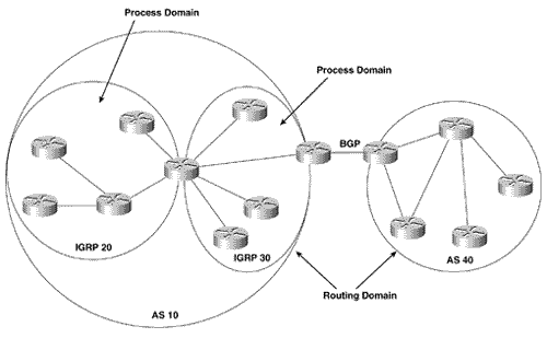
Unlike RIP, which is accessed via UDP, the IGRP process is accessed directly from the IP layer as protocol 9. IGRP also utilizes the concept of autonomous systems. Recall from Chapter 4,"Dynamic Routing Protocols," that an autonomous system can be defined either as a routing domain or as a process domain. An IGRP autonomous system is an IGRP process domain ”a set of routers whose common routing protocol is an IGRP process. By defining and tracking multiple autonomous systems, IGRP allows the establishment of multiple process domains within an IGP environment, isolating the communications within one domain from the communications within another domain. Traffic between the domains can then be closely regulated by redistribution (Chapter 11, "Route Redistribution") and route filtering (Chapter 13, "Route Filtering"). Figure 6.1 illustrates the contrast between process domains and routing domains. Here two autonomous systems (ASs) are defined: AS 10 and AS 40. These systems are routing domains “a set of routers running one or more IGPs under a common administration. They communicate via an Exterior Gateway Protocol (in this case, Border Gateway Protocol, or BGP). Figure 6.1. An autonomous system number may specify a routing domain, which is a group of routers running one or more IGP processes under a single administrative domain. An autonomous system number may also specify a process domain, which is a group of routers sharing routing information by means of a single routing process. Within AS 10 are two IGRP process domains: IGRP 20 and IGRP 30. Under IGRP, the 20 and 30 are defined as autonomous system numbers. In this context the numbers serve to distinguish two routing processes within the same routing domain. IGRP 20 and IGRP 30 communicate via the single router connected to both domains. This router runs both IGRP processes and redistributes between them. The configuration section of this chapter includes a case study demonstrating the configuration of multiple IGRP process domains. Within its updates, IGRP classifies route entries into one of three categories: interior routes, system routes, and exterior routes. An interior route is a path to a subnet of the network address of the data link on which the update is being broadcast. In other words, a subnet advertised as an interior route is "local" to the major network to which the advertising router and the receiving router are commonly connected . A system route is a path to a network address, which has been summarized by a network boundary router. An exterior route is a path to a network that has been flagged as a default network . A default network is an address to which a router will send any packet that cannot be matched to a more specific destination. [2] Default networks and their configuration are covered in Chapter 12, "Default Routes and On-Demand Routing."
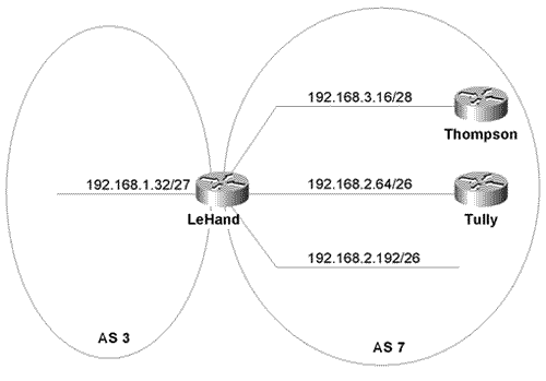
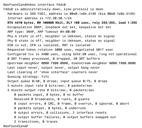
Figure 6.2 shows how IGRP uses these three categories. The routers LeHand and Tully are connected to subnet 192.168.2.64/26, so major network 192.168.2.0 is considered the "local" network shared by those two routers. LeHand is also attached to 192.168.2.192/26, which is another subnet of the network connecting the two routers. Therefore, LeHand advertises that subnet to Tully as an internal route. Figure 6.2. LeHand advertises subnet 192.168.2.192/26 to Tully as an internal route. Network 192.168.3.0 is advertised to Tully as a system route, and 192.168.1.0 is advertised as an external route. However, the local network for LeHand and Thompson is 192.168.3.0. LeHand is the boundary router between major networks 192.168.2.0 and 192.168.3.0, so 192.168.2.0 will be advertised to Thompson as a system route. Likewise, 192.168.3.0 is advertised to Tully as a system route. 192.168.1.0 is a network in another autonomous system, and LeHand has been configured to advertise that network address as a default route. 192.168.1.0 will therefore be advertised to both Thompson and Tully as an external route. IGRP Timers and Stability FeaturesThe IGRP update period is 90 seconds. A random jitter variable of up to 20% is subtracted from each update time to prevent update timer synchronization, so the time elapsed between individual updates will vary from 72 to 90 seconds. When a route is first learned, the invalid timer for that route is set for 270 seconds, or three times the update period. The flush timer is set for 630 seconds ”seven times the update period. Each time an update is received for the route, these timers are reinitialized. If the invalid timer expires before an update is heard , the route is marked as unreachable. It will be held in the routing table and advertised as unreachable until the flush timer expires, at which time the route will be deleted from the table. The 90-second timer used by IGRP, in comparison to the 30-second timer used by RIP, means that, compared to RIP, IGRP uses less bandwidth for periodic updates. However, the trade-off is that in some cases IGRP may be slower to converge than RIP. For example, if a router goes offline, IGRP takes three times as long as RIP to detect the dead neighbor. If a destination becomes unreachable or if the next -hop router increases the metric of a destination enough to cause a triggered update, the route will be placed in holddown for 280 seconds (three update periods plus 10 seconds). Until the holddown timer expires, no new information will be accepted about this destination. IGRP holddown may be disabled with the command no metric holddown . In loop-free topologies, where holddown has no real benefit, disabling the function can reduce reconvergence time. The default timers can be changed with the following command: timers basic update invalid holddown flush [sleeptime] This command is also used to manipulate RIP timers with the exception of the sleeptime option. Sleeptime is a timer used to specify a period, in milliseconds , to delay a regular routing update after receiving a triggered update. The default timers should be changed only in response to an observable problem and only after careful consideration of the consequences. For example, the periods might be reduced to speed up reconvergence in an unstable topology. The price to be paid is increased update traffic ”which might contribute to congestion on low-bandwidth links ”and an increased number of router CPU cycles to handle the updates. Care must be taken to ensure that the timers are adjusted equally throughout an autonomous system, and configuration management must ensure that any routers added to the autonomous system in the future also are configured with the modified timers. IGRP MetricsThe link characteristics from which IGRP calculates its composite metric are bandwidth, delay, load, and reliability. By default, IGRP chooses a route based on bandwidth and delay. If a data link is thought of as a pipe, then bandwidth is the width of the pipe and delay is the length of the pipe. In other words, bandwidth is a measure of the carrying capacity, and delay is a measure of the end-to-end travel time. Load and reliability are taken into consideration only if the router is configured to do so. IGRP also tracks the smallest Maximum Transmission Unit (MTU) along each route, although the MTU is not used in the composite metric calculation. The quantities associated with IGRP's composite metric on a specific interface can be observed with the show interfaces command Figure 6.3 Figure 6.3. The output of every show interface command includes metric statistics for the interface. This FDDI interface shows MTU = 4470 bytes, bandwidth = 100 megabits per second, delay = 100 microseconds, reliability = 100%, and load = .39% (minimum load). Note Bandwidth Bandwidth is expressed in units of kilobits. It is a static number used for metric calculation only and does not necessarily reflect the actual bandwidth of the link ”that is, bandwidth is not measured dynamically. For example, the default bandwidth of a serial interface is 1544, whether the interface is attached to a T1 or a 56K line. This bandwidth number may be changed from the default with the bandwidth command. IGRP updates use a three-octet number, referred to in this book as BW IGRP , which is the inverse of the bandwidth scaled by a factor of 10 7 . So if the bandwidth of an interface is 1544, then
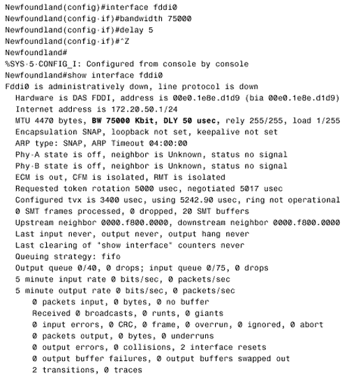
Note Delay Delay, like bandwidth, is a static figure and is not measured dynamically. It is displayed by the show interface command as DLY, in units of microseconds. The default delay of an interface may be changed with the delay command, which specifies the delay in tens of microseconds. Figure 6.4 shows the bandwidth and delay commands used to change the defaults of the interface of Figure 6.3. Figure 6.4. The bandwidth and delay commands are used to change the metric defaults of the fddi0 interface. The new quantities can be seen in the output of the show interface command. When carried in an IGRP update, delay is a three-octet number expressed in the same 10-microsecond units as specified by the delay command. To avoid confusion, this number will be referred to as DLYIGRP, to differentiate it from DLY, in microseconds, observed with show interface . For example, if DLY is 50, then
IGRP also uses delay to indicate an unreachable route by setting DLY IGRP = 0xFFFFFF. This number translates to approximately 167.8 seconds, so the maximum end-to-end delay of an IGRP route is 167 seconds. Note Changing default Values for bandwidth and delay. Because IGRP uses bandwidth and delay as its default metrics, these quantities must be configured correctly and consistently on all interfaces of all IGRP routers. Changing the bandwidth or delay of an interface should be done only for good reasons and only with a full understanding of the results of those changes. In most cases, it is best to leave the default values unchanged. A notable exception is serial interfaces. As noted earlier in this section, serial interfaces on Cisco routers have a default bandwidth of 1544 no matter what the bandwidth is of the connected link. The bandwidth command should be used to set the interface to the actual bandwidth of the serial link. It is also important to note that OSPF also uses the bandwidth statement to calculate its metric. Therefore, if IGRP metrics must to be manipulated in an internet where both IGRP and OSPF are running, use the delay to influence IGRP. Changing the bandwidth will affect both IGRP and OSPF. Table 6.1 lists the bandwidths and delays for a few common interfaces. (The default bandwidth of a serial interface is always 1544; Table 6.1 shows the figures that would result from using the bandwidth command to reflect the actual connected bandwidth.). Table 6.1. Common BW IGRP and DLY IGRP quantities.
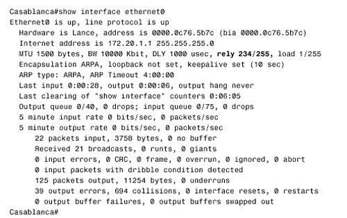
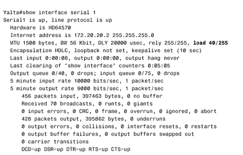
Note Reliability Reliability is measured dynamically and is expressed as an eight-bit number, where 255 is a 100% reliable link and 1 is a minimally reliable link. In the output of show interface , reliability is shown as a fraction of 255, for example, 234/255 (Figure 6.5). Figure 6.5. This interface shows a reliability of 234/255, or 91.8%. Note Load Load, in an IGRP update, is an eight-bit number. Load is represented in the output of show interface as a fraction of 255, such as 40/255 (Figure 6.6); 1 is a minimally loaded link, and 255 is a 100% loaded link. Figure 6.6. This interface shows a load of 40/255, or 15.7%. If reliability or load is to be used as a metric or as part of a composite metric, the algorithm for calculating the metric must not allow sudden changes in the error rate or channel occupancy to destabilize the internetwork. As an example, if a "raw," or instantaneous, measure of load is used, a burst of heavy traffic could cause a route to go into holddown and an abrupt drop in traffic could trigger an update. To prevent frequent metric changes, reliability and load are calculated based on an exponentially weighted average with a 5-minute time constant, which is updated every 5 seconds. The composite metric for each IGRP route is calculated as where BW IGRP(min) is the minimum BW IGRP of all the outgoing interfaces along the route to the destination and DLY IGRP(sum) is the total DLY IGRP of the route. The values k1 through k5 are configurable weights; their default values are k1=k3=1 and k2=k4=k5=0. These defaults can be changed with the command:
If k5 is set to zero, the [k5/(RELIABILITY+k4)] term is not used. Given the default values for k1 through k5, the composite metric calculation used by IGRP reduces to the default metric:
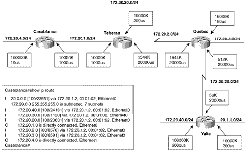
The network example in Figure 6.7 shows the bandwidths and delays configured on each interface and a forwarding database from one of the routers with the derived IGRP metrics. [4]
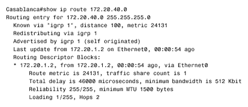
Figure 6.7. By default, the total delay is added to the minimum bandwidth to derive the IGRP metric. The routing table itself shows only the derived metric, but the actual variables recorded by IGRP for each route can be seen by using the command show ip route address , as in Figure 6.8. Here the minimum bandwidth on the route from Casablanca to subnet 172.20.40.0/24 is 512K, at Quebec. The total delay of the route is (1000 + 20000 + 20000 + 5000) = 46000 microseconds.
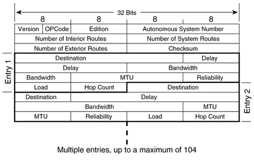
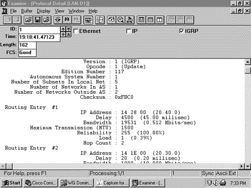
Figure 6.8. The metric for the route from Casablanca to subnet 172.20.40.0 is calculated from the minimum bandwidth of 512K and the total delay of 46000 microseconds. Figure 6.8 shows that IGRP also records the smallest MTU along the route as well as the hop count. MTU is not used in the metric calculation. Hop count is the hop count reported by the next-hop router and is used only to limit the diameter of the network. By default, the maximum hop count is 100 and can be configured from 1 to 255 with the command metric maximum-hops . If the maximum hop count is exceeded, the route will be marked unreachable by setting the delay to 0xFFFFFF. Note that all metrics are calculated from the outgoing interfaces along the route. For example, the metric for the route from Yalta to subnet 172.20.4.0/24 is different from the metric for the route from Casablanca to subnet 172.20.40.0/24. This is due to the differences in the configured bandwidth on the link between Yalta and Quebec and to the differences in the delay on the outgoing interfaces to the two destination subnets. IGRP Packet FormatThe IGRP packet format is shown in Figure 6.9. The efficient design, in comparison to the RIP format of Figure 5.3, is readily apparent. At the same time, IGRP updates provide much more information than RIP, which sends little more than a snapshot of the sender's routing table. No field is unused, and after the 12-octet header the individual route entries appear one after the other. In contrast to RIP, IGRP does not use padding to force each entry to end on a 32-bit word boundary. Each update packet can carry a maximum of 104 fourteen-octet entries, so with the 12-octet header the maximum IGRP packet size is 12 + (104 X 14) = 1468 octets. Adding a 32-octet IP header brings the maximum IGRP packet size to 1500 bytes. Figure 6.9. The IGRP packet format. Version will always be set to one. Opcode will be one for an IGRP Request packet and two for an IGRP Update packet. A Request packet consists of a header with no entries. Edition is incremented by the sender of an update whenever there is a change of routing information. The edition number helps the router avoid accepting an old update that arrives after the newer update. Autonomous System Number is, more accurately, the ID number of the IGRP process. This tag allows multiple IGRP processes to exchange information over a common data link. Number of Interior Routes is the number of entries in the update that are subnets of a directly connected network. If none of the directly connected networks is subnetted , this field will be zero. Interior route entries always appear first in the update. This field, along with the subsequent fields for number of system routes and number of exterior routes, tell an IGRP process how many 14-octet entries are contained in the packet and hence the packet length. Number of System Routes tells the number of routes to networks that are not directly connected ”in other words, routes that have been summarized by a network border router. The entries numbered in this field, if any, follow the interior route entries. Number of Exterior Routes is the number of routes to networks that have been identified as default networks. The entries numbered in this field, if any, appear last in the update. Checksum is calculated on the IGRP header and all entries. To calculate the checksum, the field is set to zero and the 16-bit one's complement sum of the packet (not including the IP header) is calculated. The 16-bit one's complement of that sum is then stored in the checksum field. Upon receipt, the 16-bit one's complement of the packet is again calculated, this time including the transmitted checksum field. When performed on an error-free packet, the result will be all ones (0xFFFF). Destination is the first field of each route entry. It may seem odd at first glance that the field is only three octets long, given that IP addresses are four octets. As it turns out, a destination can be made recognizable in three octets because of IGRP's route categorization. If the entry is an interior route, at least the first octet of the IP address will always be known from the address of the interface on which the update was received. Therefore, the destination fields of interior route entries will contain only the last three octets of the address. Similarly, if the entry is a system or external route, the route will have been summarized and at least the last octet will be all zeros. Therefore the destination fields of system and external route entries will contain only the first three octets of the address. For example, if an interior route of 20.40.0 is received on interface 172.20.1.1/24, it is recognized as subnet 172.20.40.0/24. Similarly, if system routes 192.168.14 and 20.0.0 are received, IGRP will understand these destinations as major network addresses 192.168.14.0 and 20.0.0.0. Delay is the 24-bit DLY IGRP(sum) previously explained ”the sum of the configured delays expressed in units of 10 microseconds. Bandwidth is the 24-bit BW IGRP(min) previously explained ”10,000,000 divided by the lowest configured bandwidth of any interface along the route. MTU is the smallest Maximum Transmission Unit of any link along the route to the destination. Although an included parameter, it has never been used in the calculation of metrics. Reliability is a number between 0x01 and 0xFF that reflects the total outgoing error rates of the interfaces along the route, calculated on a five-minute exponentially weighted average. Load is also a number between 0x01 and 0xFF, reflecting the total outgoing load of the interfaces along the route, calculated on a five-minute exponentially weighted average. Hop Count is a number between 0x01 and 0xFF indicating the number of hops to the destination. A router will advertise a directly connected network with a hop count of 0; subsequent routers will record and advertise the route relative to the next-hop router. For example, in Figure 6.8 Casablanca shows subnet 172.20.40.0 to be two hops away. Figure 6.7 shows the meaning of the hop count: 172.20.40.0 is two hops from the next-hop router, Teheran. An analyzer decode of a portion of an IGRP update packet is shown in Figure 6.10. Figure 6.10. The header and the first entry of an IGRP update can be seen in this analyzer decode. |
