4.6. Interface Databases There are two databases in which an OSPF or IS-IS router stores information about its immediate environment: the interface and the neighbor database. The OSPF or IS-IS interface database records all the router interfaces on which the protocol is enabled and the interface parameters relevant to the protocol. The neighbor database likewise records all known neighbors and neighbor parameters, mostly based on the information from received Hello messages. This section examines interface databases for OSPF and IS-IS. IS-IS neighbor databases could also be examined in this chapter, because IS-IS neighbors are adjacent after bidirectional communication is established. But OSPF neighbors are not fully adjacent until after database synchronization, and many of the states recorded in its neighbor database refer to steps in the synchronization process. For that reason, neighbor databases are described in Chapter 6, which discusses link state database synchronization. 4.6.1. The OSPF Interface Data Structure Each router interface running OSPF has an interface data structure associated with it, and the collection of those structures comprises the interface database. Figure 4.33 shows most of the database entry for an OSPF interface. Figure 4.33. The data for an OSPF interface from the interface database.[View full width] jeff@Juniper6> show ospf interface fe-0/0/2.0  extensive Interface State Area DR ID BDR ID Nbrs fe-0/0/2.0 BDR 0.0.0.0 192.168.254.7 192.168.254.6 1 Type LAN, address 192.168.4.1, mask 255.255.255.0, MTU 1500, cost 1 DR addr 192.168.4.2, BDR addr 192.168.4.1, adj count 1, priority 128 Hello 10, Dead 40, ReXmit 5, Not Stub extensive Interface State Area DR ID BDR ID Nbrs fe-0/0/2.0 BDR 0.0.0.0 192.168.254.7 192.168.254.6 1 Type LAN, address 192.168.4.1, mask 255.255.255.0, MTU 1500, cost 1 DR addr 192.168.4.2, BDR addr 192.168.4.1, adj count 1, priority 128 Hello 10, Dead 40, ReXmit 5, Not Stub
|
Although the format in which the router displays such information varies from vendor to vendor (Figure 4.33 is taken from a Juniper Networks router), in each case the interface data structure contains the same essential information: Type indicates the OSPF network type to which the interface is attached (broadcast, nonbroadcast, NBMA, point to multipoint, or virtual link). In Figure 4.33, you can see that the network type is LAN (broadcast). State is the functional level of the interface, as described in the next chapter. The router decides whether adjacencies can be formed on the interface state. The state of the interface in Figure 4.33 is BDR (backup), indicating that this router is the BDR on the network to which this interface is attached. IP Interface Address is the IP address assigned to the interface, and the source address of all OSPF packets sent out the interface. If the interface is unnumbered, of course, no IP address is assigned to it and this entry is empty. The address of the interface in Figure 4.33 is 192.168.4.2. IP Interface Mask indicates the portion of the IP interface address that is the IP prefix for the attached network. On virtual links and some point-to-point links, an address mask is not defined and so will not appear as a part of the interface data. The IP interface mask in Figure 4.33 is 255.255.255.0. Area ID specifies the area to which the attached network belongs. OSPF messages originated on the interface will include this AID. In Figure 4.33, the AID is 0.0.0.0. Hello Interval is the configured or default OSPF hello interval for the interface. The routers send Hellos on the attached network at this interval, and include this value in the Hello Interval field of each Hello sent. In Figure 4.33, the hello interval is 10 seconds. RouterDeadInterval is the configured or default value advertised in Hello packets sent from this interface. In Figure 4.33 the router dead interval is 40 seconds. InfTransDelay is the estimated number of seconds it takes to transmit a link state Update packet over the interface. The LSAs contained in the Update packet will have their age incremented by this amount before the packet is transmitted. (Use of the InfTransDelay value and LSA aging is discussed in Chapter 5.) No InfTransDelay is displayed in Figure 4.33, but it is nonetheless a part of this data structure. In almost all common OSPF implementations, the InfTransDelay is 1. Router Priority is the value set in the Hello packets transmitted on this interface, to be used in the DR election. The router priority in Figure 4.33 is 128, the default value used by Juniper Networks routers. Hello Timer, which is 10 seconds in Figure 4.33, is the interval between Hellos transmitted to the attached network. The hello interval in the transmitted Hellos is set to this value. Wait Timer is the time the router listens, after first becoming active on the attached network, for the presence of a DR (advertised on neighbors' Hellos). No wait timer value is displayed in Figure 4.33 because it is not a configurable value. It is, as it is in all common OSPF implementations, the same as the router dead interval. List of Neighboring Routers is the addresses of all neighbors learned from received Hellos. The router might or might not be adjacent with all the neighbors in this list. The JUNOS display in Figure 4.33 does not explicitly show this list, and instead just shows that there is one known neighbor (Nbrs) on the attached network. You can see the list with the JUNOS show ospf neighbors command. Cisco IOS does display the list along with its show ip ospf interface command. Designated Router is both the RID and the interface address of the DR for the attached network (if there is one). Figure 4.33 shows that the DR RID is 192.168.254.7, and its interface address is 192.168.4.2. Backup Designated Router is the RID and interface address of the BDR of the attached network, if there is one. Figure 4.33 shows that the BDR RID is 192.168.254.6, and its interface address is 192.168.4.1. As you already know from the interface state in the display, the displaying router is the BDR, which you can also see from the fact that the BDR interface address and the IP interface address match. Interface Output Cost is the outgoing cost of the interface. This metric, which is 1 for the interface in Figure 4.33, is advertised in Router LSAs originated by this router. RxmtInterval specifies the time the router waits, after sending LSAs on this interface, for an acknowledgement. If no acknowledgement is received after the number of seconds specified by this value, the router retransmits. The interface in Figure 4.33 has a RxmtInterval (ReXmit in the display) of 5 seconds, which is the default for both Juniper and Cisco routers. AuType is the type of OSPF authentication used on the interface. OSPF authentication is discussed in Chapter 9. Authentication Key is the secure information used for authentication when either simple password or cryptographic authentication is enabled, as described in Chapter 9. No authentication is configured for the interface in Figure 4.33.
4.6.2. OSPF Interface States Like so many OSPF components, there is a state machine for determining what state each interface should be in, based on prescribed events. The possible OSPF interface states are: Down Loopback Waiting Point-to-Point DR Other Backup DR
The interface is in the Down state when the underlying link media is unusable, either as a result of an indication from the physical or data link protocols or because the interface has been administratively disabled. No OSPF packets are sent or received on an interface in this state, all parameters are in their initial values, all timers are disabled, and no adjacencies exist. Loopback indicates that the interface is looped back either in hardware or software, usually for maintenance purposes. OSPF does not transmit any packets on an interface in this state, but it does include the interface address in the Router LSAs flooded from other interfaces to facilitate monitoring and maintenance functions such as pinging the interface. Waiting indicates that the router is attempting to determine whether a DR or BDR exists on the attached network, as indicated by received Hello packets. As discussed earlier in this chapter, the interface stays in the waiting state for a period equal to the router dead interval. The router sends Hellos (with the DR and BDR fields set to 0.0.0.0), but cannot attempt to start a DR/BDR election for the attached network while the interface is in this state. Point-to-point indicates that the OSPF network type is point-to-point or point-to-multipoint and that the interface is fully operational. OSPF packets are sent and received, and if a neighbor is detected on the link the router attempts to establish an adjacency with it. DR Other indicates that the interface is fully operational on a broadcast or NBMA network and that it is neither the DR nor the BDR. OSPF packets are sent and received, the router forms adjacencies with the DR and BDR if they exist, and it attempts to synchronize its link state database with the DR. The interface is in the Backup state when it is fully operational on a broadcast or NBMA network and the router has been elected as the BDR. In this state, the router established adjacencies with all other routers on the network but does not perform database synchronization. The interface state is DR when the interface is fully operational on a broadcast or NBMA network and the router has been elected the DR for the network. The router attempts to become adjacent with all other routers on the network, synchronizes its link state database with all adjacent routers, and originates a Network LSA to represent the network as a pseudonode.
Figure 4.34 shows a diagram of the OPSF interface state machine. The events causing an interface state change are: InterfaceUp Lower-level protocols have indicated that the interface is up. Or, in the case of virtual links, this event is triggered by the SPF calculation. WaitTimer The wait timer has expired. BackupSeen A Hello packet is received from a neighbor with which bidirectional communication has been established, and which either lists itself as the BDR or which lists itself as the DR and indicates that there is no BDR. NeighborChange An event caused by one of the following: Bidirectional communication has been established with a neighbor. Bidirectional communication is lost with a neighbor. A bidirectional neighbor is newly declaring itself the DR or BDR. A bidirectional neighbor is no longer declaring itself the DR or BDR. The router priority value in a bidirectional neighbor's Hello has changed. A NeighborChange event triggers a DR/BDR election.
LoopInd The interface is looped back. UnLoopInd The interface loopback has been dropped. InterfaceDown Lower-level protocols indicate that the interface is down. The interface can be in any state prior to this event.
Figure 4.34. The OSPF interface state machine. 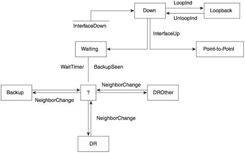
A detailed description of the events causing OSPF interface state changes, and the results of those changes, is provided in RFC 2328, Section 9.3. Figure 4.35 shows a log file capture of an interface that failed and then was restored (by means of the author removing and replacing its Ethernet connector). The interface becomes the DR after the WaitTimer event indicates that the wait timer expired without another DR or BDR being detected on the network. Notice from the timestamps that the WaitTimer event happens exactly 40 secondsthe default router dead intervalafter the interface state changed from down to waiting.
Figure 4.36 shows another example of state changes, due to the same mischief with Ethernet connectors. This time, there is a neighbor on the interface, so there are two NeighborChange events due to bidirectional communication being lost and then established with the neighbor. A Hello is seen from the neighbor causing a BackupSeen event just 1 second after the interface enters the Waiting stage, and the router becomes the BDR on this network. Notice that the expiration of the wait timer again causes a WaitTimer event exactly 40 seconds after the interface enters the Waiting state; because the interface is already in the BDR state, however, the event causes no state change.
4.6.3. The IS-IS Interface Data Structure As with OSPF, IS-IS maintains a database of its interface parameters. Figure 4.37 shows an example of the data structure associated with a single interface. Figure 4.37. The data for an IS-IS interface from the interface database.[View full width] jeff@Juniper6> show isis interface fe-0/0/2.0 extensive IS-IS interface database: fe-0/0/2.0 Index: 3, State: 0x6, Circuit id: 0x3, Circuit type: 3 LSP interval: 100 ms, CSNP interval: 10 s Level 1 Adjacencies: 0, Priority: 64, Metric: 10 Hello Interval: 9 s, Hold Time: 27 s Level 2 Adjacencies: 1, Priority: 64, Metric: 10 Hello Interval: 9 s, Hold Time: 27 s Designated Router: Juniper7.02 (not us)
|
Index is just a JUNOS kernel assignment for tracking the interface, and has nothing to do with open IS-IS implementation. Likewise, State also relates to the internal state machine of the Juniper Networks IS-IS implementation and is not part of the open standard. In fact, unlike OSPF, ISO 10589 does not specify any kind of state machine for IS-IS interfaces. The interface is either up or down, according to the underlying physical and data link protocols. Circuit ID is the identifier that IS-IS assigns to all interfaces on the router to differentiate one interface from another. It normally has only local significance, although it is included in the Local Circuit ID field of Point-to-Point Hellos. Circuit Type identifies the type value, as listed in Table 4.1 earlier in this chapter: 1 for level 1 only, 2 for level 2 only, and 3 for both. The interface in Figure 4.37 is type 3, supporting both level 1 and level 2. LSP Interval is the interval between the transmission of multiple LSPs. In Figure 4.37, the LSP interval is 100ms. CSNP Interval is the interval between periodic transmissions, if the router is the DIS on the attached interface, of CSNP PDUs (used for link state database synchronization, as described in Chapter 6). In Figure 4.37, the CSNP interval is 10 seconds, the default.
Because the circuit type is 3, indicating support for both level 1 and level 2 adjacencies, the remaining parameters are specified separately for level 1 and level 2, indicating that they can be configured separately for each level: Adjacencies specifies the number of existing adjacencies on the interface. You can see that the interface in Figure 4.37 has one level 2 adjacency and no level 1 adjacencies. Priority is the value added to the LAN Hellos transmitted out this interface to be used in the election of the DIS. In Figure 4.37, the priority is 64 for both levels. Metric is the outgoing cost of the interface. The interface in Figure 4.37 has a metric of 10 for both levels. Hello Interval is the interval, in seconds, between the periodic transmission of Hellos to the attached link. The Hello interval in Figure 4.37 is 9 seconds. Hold Time is the time, in seconds, advertised in Hellos sent on the attached network. It tells adjacent neighbors on the link the maximum time to wait for a Hello from this router before declaring the router dead. The hold time for both levels in Figure 4.37 is 27 secondsthree times the hello interval, which is the usual default.
You can also see in Figure 4.37 that the DIS for the single level 2 adjacency is identified. Figure 4.38 shows the entries in a JUNOS traceoptions file made when, as was done in Figures 4.35 and 4.36, the Ethernet connector was disconnected and reconnected. You can readily see that the interface is either down or up, unlike the states associated with OSPF interfaces. There is state associated with the adjacency on the interface, but even that is a simple three-step state change. Figure 4.38. JUNOS traceoptions log entries of state changes on an IS-IS interface.[View full width] jeff@Juniper6> show log isis_state Nov 23 01:44:31 ISIS link layer change on interface fe-1/1/0.0 Nov 23 01:44:31 ISIS interface fe-1/1/0.0 down Nov 23 01:44:31 Adjacency state change, Juniper5, state Up -> Down Nov 23 01:44:31 interface fe-1/1/0.0, level 2 Nov 23 01:44:31 ISIS interface fe-1/1/0.0 down Nov 23 01:44:34 ISIS link layer change on interface fe-1/1/0.0 Nov 23 01:44:34 ISIS interface fe-1/1/0.0 up Nov 23 01:44:37 Adjacency state change, Juniper5, state Down -> New Nov 23 01:44:37 interface fe-1/1/0.0, level 2 Nov 23 01:44:38 Adjacency state change, Juniper5, state New -> Initializing Nov 23 01:44:38 interface fe-1/1/0.0, level 2 Nov 23 01:44:40 Adjacency state change, Juniper5, state Initializing -> Up Nov 23 01:44:40 interface fe-1/1/0.0, level 2
|
|