8.2 What Is Architectural Design?
| The analysis model identifies objects, classes, and relationships but does not specify how they are organized into large-scale structures. As shown in Table 8-1, architectural design is concerned with large-scale design decisions involving collaborations of packages, tasks, or processors. The ROPES process defines two fundamental kinds of architecture logical and physical.[1] Logical architecture refers to the organization of things that exist only at design time that is, the organization of classes and data types. Logical architecture is concerned with how models are themselves organized; this organization can be simple or very complex, depending on the needs and structure of the team(s) using it. The logical architecture is unrelated to the organization of the system at runtime, although one logical architecture pattern is to mirror the physical architectural structure. Figure 8-2 shows the roles of logical and physical architectures.
Figure 8-2. Logical and Physical Architecture
The primary place that architectural design work is done is, naturally enough, the architectural design part of the design phase. Here, strategic design decisions are made in each of the five views (or four views, if the subsystem architecture is already defined in the systems engineering part). These views will be detailed in the next section. For the most part, architecture is done through the application of architectural design patterns. A design pattern is a generalized solution to a commonly occurring problem. Design patterns have three primary parts: a problem to be solved, the solution (the pattern), and a set of consequences. With architectural design patterns, the problem to be solved is always based in optimizing some small set of system QoS properties at the expense of others. Certain patterns optimize safety but by increasing recurring cost or complexity. Other patterns enhance reusability but at the expense of average execution time. Still others optimize predictability of execution time at the expense of optimal worst-case execution time (see [9] for many different architectural patterns for real-time systems). Patterns can be mixed and matched as necessary, although clearly some mixes won't make any sense. It is common, for example, to mix a pattern for primary subsystem organization with another pattern for allowing distributed objects to communication and another pattern for concurrency management and another pattern for fault management and still another pattern for mapping to the underlying hardware. This gives rise to the notion of different aspects of architecture. The complete architecture of the system is the melding together of all the architectural patterns used. In the ROPES process, we identify five different views of architecture. It is common to have at least one pattern from each (and in some cases, more than one pattern in each) mixed together to form the complete system architecture. 8.2.1 Logical ArchitectureThere are many ways to organize a design model. The ROPES process recommends a logical architecture based on the concept of domains. A domain is an independent subject area that generally has its own vocabulary. Domains provide a means by which your model can be organized; or partitioned into its various subjects, such as User Interface, Hardware, Alarm Management, Communications, Operating System, Data Management, Medical Diagnostics, Guidance and Navigation, Avionics, Image Reconstruction, Task Planning, and so on. This way, a domain is just a UML package used in a particular way. UML packages contain model elements, but, other than providing a namespace, packages have no semantics and are not instantiable.[2] The UML does not provide a criterion for what should go in one package versus another, but domains do. For this reason, we represent domain as a «domain» stereotyped package that includes a mission, specifically "hold classes and types around the common subject matter." The use of domains does not dictate how objects will be organized and deployed at runtime however; that is what the physical architecture is all about.
Figure 8-3 shows a typical domain diagram a package diagram that shows the relations of the domains themselves and the classes within the domains. In the figure, we see that the Alarm domain contains classes around the concept of alarm management a couple of types of alarms, an alarm manager, and an alarm filter policy class. The alarms must be displayed in a list, so the Alarm Manager associates with a Text List class that is a user interface element and so is found in the User Interface domain. Alarms themselves are displayed as text, so the Alarm class (in the Alarm domain) associates with the Text class in the User Interface domain. Alarms must also be annunciated, so the Alarm Manager associates with the Speaker class in the Hardware domain. Also, the user needs to be able to acknowledge and silence the alarm and so the Alarm Manager associates with a Button class from the Hardware domain. Figure 8-3. Logical Domain Architecture
Physical architecture is concerned with the organization of things that exist at runtime. Although packages (and therefore domains) don't exist at runtime (being solely design-time concepts), they provide a place for the definition of the classes that will be used via instantiation in the various subsystems. Domain structure usually does not completely reflect the physical architecture. For example, the physical architecture may have the notion of a Power Subsystem, which is constructed from instances of the classes defined in various domains. For example, the Power Subsystem may contain instances of many classes from a number of different domains, as shown in Figure 8-4. Using the standard name-scoping operator (::), the name of the domain package precedes the name of the class. So, for example, Hardware_Domain::Switch is the class Switch in the Hardware_Domain package, while Communications_Domain:: Message_Transaction is the Message_Transaction class in the Communications_Domain package.[3]
Figure 8-4. Relating Logical and Physical Architecture
That being said, often there may be specialized domains containing classes only instantiated in one subsystem. For example, classes from a Guidance and Navigation domain will be likely instantiated solely in a Navigation subsystem. Most domains are more general than that, however, and are represented in many, if not all, subsystems. 8.2.2 Physical ArchitecturePhysical architecture refers to the large-scale organization elements of the system at runtime, so these elements must be instantiable things. The typical elements are subsystems, components, and «active» objects, but other specialized forms, such as a channel (a kind of subsystem) may be used. These large-scale organizational elements don't do much, in and of themselves, but they organize the more primitive instances that do the real work and provide management oversight and delegation of requests and messages to the appropriate objects. They allow us to view and understand the system at different levels of abstraction. This is crucial for the construction and understanding of large complex systems. We need to look at assemblies of parts and refer to them as a single, albeit more abstract, element. Figure 8-5 shows a common set of abstraction levels. Figure 8-5. Levels of Architectural Abstraction
The most abstract level in the figure is the complete system (Level 0), such as "Mars Sample Return Mission." The next level down is the systems engineering level (Level 1), where subsystems are defined and their interfaces specified. In the Mars project example, subsystems might be "Deep Space Network," "Launch Vehicle," "Orbiter," "Lander," "Spacecraft," and "Ground System." In a systems engineering environment, these are not yet broken down into software and hardware. There can be multiple sublevels at this level of abstraction, before the system is further decomposed into hardware and software aspects. For example, the "Spacecraft" could be decomposed into (sub)subsystems such as "Guidance and Navigation," "Avionics," "Attitude Control," "Communications," and "Power Management." Next, we've decomposed the system into the engineering disciplines (Level 2): electronic, mechanical, chemical, and software. If a system uses commercial, off-the-shelf (COTS) hardware, then this step may be skipped, but if you are developing custom hardware it may be very important. Notice that hardware/software decomposition is done primarily at the subsystem level rather than at the system level. For example, a jet's attitude control subsystem can be thought of as being composed of electronic aspects (processors, relays, motors, valve controls, a variety of sensors and serial connections), mechanical parts (reaction wheels, thruster assemblies, fuel lines and mixers, and enclosures), chemicals (fuel mixture and oxygen), and, of course, software (the "smarts" to receive and interpret commands, control electronic parts that control mechanical parts that work with chemicals). The software for the subsystem may then be decomposed into its major architectural units, components, or software subsystems (Level 3). These are the major replaceable pieces of software that comprise the subsystem. For example, the components for the attitude control subsystem might include a TCP/IP communications protocol stack, math library, PID control loops for reaction wheels and thrusters, fuel management component, reaction wheel control component, and so on. Lastly, we see the thread level (Level 4). This is the level at which concurrency is managed. Some components may be passive in the sense that they execute in the thread of the caller. However, there will be at least one component (or software subsystem) that creates and executes at least one thread. These threads will be owned by design-level «active» objects that also aggregate, via composition, the so-called primitive objects that ultimately perform application services. Here, if desired, the different kinds of concurrency units (processes, threads, fibers, and so on) may be specified, if that level of detail is required. The last level is the object level (not shown). These are the primitive objects that do the real work of the system. In any particular system, there may be either a greater or fewer number of these abstraction levels depending on the complexity and scale of the system. For a cardiac pacemaker, you might represent only the system level and the thread level of architecture, while in our Mars project example, you might ultimately have as many as 8 or 10 levels. Not all of these levels need to be visible to all developers, of course. The physical architecture may be constructed from virtually any model organization and so is thought of as distinct from the organization of the model per se, although it is possible to organize your model around the physical architecture. The high-level physical architecture is usually constructed in with systems engineering phase of the ROPES spiral but may be deferred to the architectural design phase if the systems engineering phase is omitted. The ROPES process identifies the five views of (physical) architecture. These focus on more-or-less independent aspects of the large-scale runtime structure of the system. Of course, ultimately there is only one system. Limiting our perspective of the system to a single aspect allows us to focus on that aspect. The term view, used in this way, refers to showing a subset of the system model to allow a keener examination of some particular aspect. These aspects are not completely independent and in a well-formed model certainly should not conflict with one another. The best way to think about this is to understand that there is a single model underlying the system that includes the architecture. The views just look at parts of the single model that are related to each other in specific ways. So these are not independent aspects, but a filtered view that only shows certain aspects at a time. The five views of architecture defined in the ROPES process are shown in Figure 8-6. Figure 8-6. The Five Views of Architecture
These views of architecture capture structure aspects and so are typically described with UML structural diagrams. A concurrency task diagram, for example, is nothing more than a class diagram showing the structural elements related to the concurrency view things like «active» objects, message queues, semaphores, and the like. When architectural behavior is being described, it is usually the interaction of the architectural elements that is of primary concern, so primarily sequence diagrams are used. To show the behavior of the architectural element in isolation, the functionality is usually divided up into use cases for the element and then each of these may be detailed with a state chart or activity chart. Figure 8-7 shows a system view for an air traffic control system, using Rhapsody. Figure 8-7. System View
We see in Figure 8-7 the System object ACME_AirTrafficControlSystem and its environmental context. This consists of the actors[4] with which the system interacts.
8.2.3 Subsystem and Component ViewThe subsystem and component view (or subsystem view for short) identifies the large-scale pieces of the system and how they fit together. As previously mentioned, this is usually created during the systems engineering phase, but it may also be done later in the architectural design phase for projects not using a systems engineering phase. Subsystem architecture is captured using a subsystem diagram, which is really a class diagram that shows primarily the subsystems and their relations. Figure 8-8. Subsystem View
In a software-only development in which we are not concerned about the underlying hardware (or at least not very concerned), a subsystem is a runtime organization of software. It is a large-scale object that contains, via composition, part objects that do the real work of the subsystem. The criteria for inclusion in the subsystem is common behavioral purpose, that is, the objects included in the subsystem are there because they contribute to the subsystem's use case realization. Software subsystems give us a way to think about systems at different levels of decomposition rather than just as a flat sea of relatively undifferentiated objects. The subsystem concept can be used in a couple of ways. Subsystems can be used to reason about systems before they are broken down into hardware and software parts, as discussed in the previous section. You may also use subsystems as a software-only concept. In either case, a subsystem is a really big object that provides well-defined interfaces and delegate service requests to internal hidden parts. How you use these UML building blocks is up to you. UML provides a vocabulary but it's up to you to write the story. If you use a component-based development approach, the components are also architectural elements. The UML has a different icon for components, although UML 1.x is not prescriptive about the differences between a component and a subsystem. In the UML, a subsystem is basically a big object that contains part objects that do the real work of the subsystem. A component, on the other hand, is a replaceable part of the system. Typically, components use a component framework for loading and unloading components, component identification, and so on. In the UML 2.0, a component is a kind of structured classifier, and a subsystem is a kind of component. This doesn't address how components and subsystems should be used. Is a component bigger or smaller than a subsystem? How should they be mixed and matched? The UML does not say anything about these issues. As a general rule, I recommend that subsystems be the largest-scale parts of a system and that these may be internally decomposed into components, as desired. The UML component diagram is just another structural diagram, one that emphasizes the component aspects of the system. An example of a component diagram is given in Figure 8-9, which shows the components for the Display_Subsystem of the ACME_AirTrafficControl System. Figure 8-9. Component View
There are patterns that can help you effectively use these elements to architecturally structure your system. [9] provides a number of the ones that have particular relevance to real-time and embedded systems. 8.2.4 Concurrency and Resource ViewThe concurrency and resource view of the system architecture focuses on the management of resources and the concurrent aspects of system execution. Because of the importance of this aspect, it is the subject of several chapters in [9]. By concurrent, we mean that objects may execute in parallel rather than sequentially. We are stating that we neither know nor care about the relative order of execution of actions between the threads[5] except where specifically mentioned. These points of synchronization are often called rendezvous and are the hard parts of concurrency modeling. Sharing data and information is a common reason for threads to rendezvous and synchronize. Another is the need to control and coordinate asynchronously executing system elements.
A resource is an element that has a finite and quantifiable aspect to its provided service. For example, it may allow only one actor at a time access its internal data. Since the hard parts of concurrency have to do with the sharing of resources, resources are treated in the same architectural view as concurrency. Figure 8-10 shows a task diagram for the Alarm_Subsystem done in UML a class diagram that emphasizes the task structure. All the «active» objects are shown with a heavy border (standard UML). Additionally, they may have «task» stereotype. Some of the classes show the stereotype as text while others use an icon. Similarly, the figure contains two «resource» objects AlarmList and ListView. The first is associated with a semaphore (shown to its left) that manages the serialization of requests. The second is managed by its owning thread, Alarm_Annunciation_Thread, which, incidentally, has a «MessageQueue» object to manage information sharing. Figure 8-10. Concurrency and Resource View
«Active» objects are the primary means for modeling concurrency in the UML. An «active» object owns the root of a thread and manages the execution of the thread and delegation of messages from the thread message queue to the appropriate objects. There are a number of common strategies for identifying threads that will be later reified as «active» objects:
The single event groups strategy creates a separate thread for every event, and that event pends on its occurrence. This strategy is useful for simple systems but doesn't scale up to large complex systems well. The event source strategy creates a thread for each source of an event and pends on any event from that source. It is useful when you have a small number of event sources and relatively simple designs. The related information strategy creates a thread that manages all data within a topic or subject matter, such as all information related to cardiac health. In an anesthesia machine, this information might include pulse rate (from a blood pressure monitor), heart rate (from an ECG monitor), preventricular contraction count, cardiac output, stroke volume, temperature of the blood coming from the superior vena cava and emptying in the right atrium, and so on. This information comes from a variety of sources and a single thread could manage it. This strategy is effective for sensor fusion applications that require significant processing of data from disparate sources. Further, this strategy tends to reduce the number of thread rendezvous, which can be a source of significant overhead. The interface device strategy is a specialized form of event source strategy that is used for systems with multiple data and command buses. One or more threads are spawned to manage the bus traffic and related processing. The recurrent properties strategy is a demonstrably optimal strategy for thread selection when schedulability of the threads is an important concern. The recurrence properties include whether or not the event set processed by the thread is periodic (time-based) or aperiodic (event-based). Periodic tasks execute and do work every so often with a defined frequency of execution. It is common to have several periodic tasks, each handling events that occur in a common time frame, such as one for the 10 ms-based events, one for the 100 ms-based events, and another for the 250 ms-based events. Aperiodic events can either be handled by a general aperiodic event handler, or you can introduce a separate thread for each aperiodic event (as in the single event group strategy). Most systems must process a combination of periodic and aperiodic events. The target object strategy creates a thread for a few special objects that are the target of events from disparate sources. For example, database or data manager objects sometimes have threads assigned to them so they can do appropriate processing when processing cycles are available. The safety level strategy creates threads for managing safety and reliability functionality, such as the execution of periodic built-in tests (BITs), stroking watchdogs, monitoring actuation to ensure that it is proceeding correctly, and so on. No matter how you come up with the set of threads you decide you want to use, the common development approach is to first construct the collaborations sets of objects working together to realize a use case then identify the set of threads and create an «active» object for each thread. Each primitive object from the collaboration is aggregated via composition by the appropriate «active» object allowing it to execute in the appropriate thread. 8.2.5 Distribution ViewThe distribution view deals with how objects find and collaborate with each other even though they may be in different address spaces. The distribution view includes policies for how the objects communicate, including the selection and use of communication protocols. In asymmetric distribution architectures, an object is dedicated to a particular address space at design time. This makes finding that object simple during runtime because the other objects can be granted a priori knowledge about how to locate and contact the object in question. In symmetric distribution architectures, the location of an object isn't decided until runtime. Symmetric architectures are useful for a complex system that must dynamically balance processing load over multiple processors. When objects become ready to run, the distributed OS runs the object in an optimal locale, based on the current loadings on the various processors. This improves overall performance but at a cost increased complexity. How, for example, can objects find each other during runtime? This is the subject of the distribution patterns in [9]. The broker architecture in Figure 8-11 is used to mediate communication among distributed objects. In this case, the objects are to participate in a possibly distributed communications subclass of the Communicating Object class. We see that this class has the stereotype «CORBAInterface». Rhapsody produces the CORBA interface description language (IDL) automatically for you; for other tools, you will probably have to write the IDL manually. The IDL generates code that produces the Client_Side_Proxy and Server_Side_Proxy classes. These encapsulate information on how to serialize the data and contact the broker. The Broker object is typically purchased from an object request broker (ORB) vendor and provides connection and naming (and a whole host of other) distribution services. The Bridge object allows ORBs to communicate across multiple networks. In a sufficiently capable tool, you will only have to write the classes you want to communicate and specify that they have the «CORBAInterface» interface, and the tool will generate all the rest of the code for the distribution. In less capable tools, each of these classes will need to be generated by hand. Figure 8-11. Distribution View
Selecting a distribution architecture is highly driven by the QoS of the collaboration. The most relevant QoS to drive the distribution architecture include
Of course, in real-time and embedded systems performance can be crucial to success. In hard real-time and safety-critical systems, worst-case delivery time is the most important. For example, control loops are notoriously sensitive to time delays. To implement distributed closed-loop control systems, you want an architecture with short and predictable worst-case delivery times for certain messages, implying that a priority-based message delivery scheme might be the most appropriate. In such a case, using an asymmetric architecture (or some variant of the observer pattern) with a predictable priority-based transport protocol might fit the system performance needs for example, an asymmetric distribution on top of a bit-dominance protocol, such as the CAN bus protocol. Ethernet is a common, but less-than-optimal choice in such cases, as it is based on a Collision-Detect Multiple Access (CDMA) protocol, meaning that while the bus is multimastered, collisions (multiple sources attempting to transmit at the same time) can occur. When they occur with the Ethernet protocol, the senders stop trying to transmit and retry later at random times. This means that Ethernet networks saturate at about 30% utilization. Above that point, Ethernet spends an inordinate amount of time resolving transmission collisions and little time actually sending information. Ethernet can be used for hard real-time distribution when very lightly loaded (meaning that collisions are rare) or when the message delivery time is a small part of the overall execution budget. In so-called soft real-time systems, the average performance is a more important criterion that worst-case performance. Average performance may be measured in terms of average length of time for message delivery or in "mean-lateness" of the messages. Such systems usually don't care if a small set of the messages is late when the system is under load, as long as the average response is sufficient. It may even, in some case, be permissible to drop some messages altogether when the system is under stress. For example, a broker pattern with a CDMA transport protocol such as UDP transport protocol on top of an Ethernet network protocol will serve this purpose well if the average load is low. For systems in which peak loads are few and far between, and individual message delivery times are not crucial, CDMA can be a good choice. Interestingly, many systems are built on TCP/IP even when it is a demonstrably poor choice given the quality of service requirements for the system. Time Division Multiple Access (TDMA) protocols work by dividing up available communication time among the devices on the bus. Each device gets to transmit for a certain period of time and then passes along a master token to the next device on the bus. TDMA protocols have low communication arbitration overhead but don't scale up to large numbers of devices well. Further, like a round robin approach to task scheduling, such a system is not responsive in an event-driven application because an event requiring transmission must wait until the owning device has the master token. Priority-based protocols typically have more overhead on a per-message basis, but allow higher-priority messages through first at the expense of lower-priority messages, making it a natural fit for systems in which scheduling is primarily priority-driven. Bit-dominance protocols are a common way to achieve priority-based messaging. In a bit-dominance protocol, each sender listens to what appears on the bus while it's transmitting; low-priority bits are the passive state of the bus and high-priority bits are the active state. If a higher-priority bit occurs in the bus when it sent out a lower-priority bit, then it assumes that it is in conflict with a device trying to send out a higher-priority message, and it drops out to retry later. The device sending out the higher-priority message wins and keeps transmitting. For example, this is how the CAN bus protocol works. Each message contains a priority sequence called a message identifier, followed by the message contents. If each message has a unique identifier, then it has a unique position in the priority scheme. An issue with the CAN bus protocol is that it allows only 8 bytes of data per message, requiring larger messages to be fragmented into multiple bus messages during transmission and reassembled at the receiver end. The SCSI bus is another example of a priority-based transmission protocol, but the SCSI bus is also a parallel bus meaning that it can achieve greater bandwidth. Complicating its use as a general message passing bus, however, is the fact that the priority is not based on the message but on the device transmitting the message. Reliability for distribution means the reliability of correct message delivery. There are many reasons why messages might not be properly delivered, such as attenuation due to distance, interference with electrical noise, temporary or permanent failure of the media or associated device, and software or hardware design flaws. These things may be handled by adding complexity into the communications protocol to check the integrity of messages and to retry transmission if the message is either corrupted or not delivered. Of course, redundant buses are a solution as well, with the advantage of improved reliable and timeliness in the presence of errors, but at a higher recurring cost.[6]
Software solutions for message integrity usually require the addition of some level of redundancy, such as a parity bit (very light weight), checksum (lightweight), or cyclic redundancy check (CRC). Of these, the best is CRC because it will identify all single and dual bit errors as well as a very high percentage of multiple-bit errors. CRCs are somewhat more complex to compute than a checksum, but a table-driven CRC computation can be very fast and hardware chips are available that can compute a CRC from a serial bit stream. Another approach is the use of Hamming codes. Hamming codes are codes that are differentiated by what is called a Hamming distance the minimum number of bit errors necessary to come up with an incorrect, but valid code. For example, in an 8-bit byte, the codes in Table 8-2 have a Hamming distance of 2 because they require two bits to be modified before you can come up with another valid code.
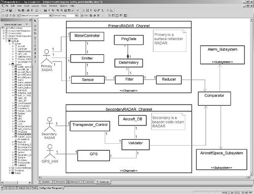
The use of Hamming codes provides some protection against bit errors because it requires multiple bit errors to construct another valid possibility. It is even possible to send the message multiple times (usually twice, if error detection is required, and thrice if error correction is needed). If the message data is sent twice, then the second copy can be sent as a ones-complement of the original so that stuck-at bit errors can be detected. 8.2.6 Safety and Reliability ViewThe safety and reliability view examines how system redundancy is defined and managed, in order to raise system reliability and safety. The safety and reliability architecture is concerned with correct functioning in the presence of faults and errors. Redundancy may be used in many ways to get different degrees and types of safety and reliability. In Figure 8-12, heterogeneous redundancy (also known as diverse redundancy) is used to provide protection from failures and errors. The Primary Radar channel processing surface reflection RADAR information produces three-dimensional position (in terms of direction, range, and azimuth) as well as velocity using the Doppler effect. The Secondary channel uses the beacon return codes to get a transponder code from the aircraft and the aircraft's position and velocity information. Figure 8-12. Safety and Reliability View
Reliability is a measure of the up-time or availability of a system specifically, it is the probability that a computation will successfully complete before the system fails. It is normally estimated with mean time between failure (MTBF). MTBF is a statistical estimate of the probability of failure and applies to stochastic failure modes. Reducing the system downtime increases reliability by increasing the MTBF. Redundancy is one design approach that increases availability because if one component fails, another takes its place. Of course, redundancy only improves reliability when the failures of the redundant components are independent.[7] The reliability of a component does not depend on what happens after the component fails. Whether the system fails safely or not, the reliability of the system remains the same. Clearly the primary concern relative to the reliability of a system is the availability of its functions to the user.
Safety is distinct from reliability. A safe system is one that does not incur too much risk to persons or equipment. A risk is an event or condition that can occur but is undesirable. Risk is the product of the severity of the incident and its probability. The failure of a jet engine is unlikely, but the consequences can be very high. Thus the risk of flying in a plane is tolerable; even though it is unlikely that you would survive a crash from 30,000 feet, such an incident is an extremely rare occurrence. At the other end of the spectrum, there are events that are common, but are of lesser concern. There is a risk that you can get an electric shock from putting a 9-volt battery in a transistor radio. It could easily occur, but the consequences are small. Again, this is a tolerable risk. The key to managing both safety and reliability is redundancy. For improving reliability, redundancy allows the system to continue to work in the presence of faults because other system elements can take up the work of the broken one. For improving safety, additional elements are needed to monitor the system to ensure that it is operating properly; other elements may be needed to either shut down the system in a safe way or take over the required functionality. 8.2.7 Deployment ViewThe deployment view focuses on how the software architecture maps onto the physical devices such as processors, disk drives, displays, and so on. The UML uses the concept of a node to represent physical devices. Nodes are often stereotyped to indicate the kind of hardware they represent. Some developers may only differentiate between processors (devices that execute code that you write) and devices (ones that don't), while others prefer to identify more detail such as whether a device is a stepper motor, DC motor, thermometer, IR sensor, and so on. Figure 8-13 is a typical UML deployment diagram. Most stereotypes are shown using icons, but text in guillemots (e.g., «Bus») can be used as easily; it is a matter of personal preference. This deployment diagram shows two «Bus» devices, several different processors, redundant flight recorder devices, and redundant display controllers. The diagram also indicates some of the components executing on selected processors. Figure 8-13. Deployment View
The primary use for the deployment view is to represent asymmetric deployment architectures. Then the hardware platform can be schematically represented and the mapping of software subsystems and components can be detailed. For asymmetric systems this is particularly important to understanding how the software on the different processors will collaborate and permits performance analysis. You can either nest the software components inside the system or use a dependency from the component or software subsystem to indicate that the node supports or executes that software element. Figure 8-13 shows a couple of nodes with components nested inside them. Any software element can be shown in this way, but showing components and subsystems this way makes the most sense. For symmetric architectures, the deployment diagram is perhaps less interesting, but only marginally so. The underlying hardware is even then a mixture of symmetric and asymmetric aspects. The interesting part, the execution of software elements on the nodes, is in principle not known when the deployment diagram is drawn at design time. In some cases, a software element might even migrate from one node to another. The UML provides the «becomes» stereotype of the dependency relation to indicate that an element might move from one node to another, such as might happen in the event of a fault on the original processor. 8.2.8 Physical Architecture IssuesSystem architectural design is broader in scope than just software and involves the hardware architecture as well, including electronic and mechanical design. Naturally, hardware architecture has a great impact on the software architecture. Together, hardware and software architectures combine to form the system architecture. In most embedded systems, the system architecture is by necessity a collaborative effort among engineers from a wide variety of disciplines, including software, electronics, mechanics, safety, and reliability. The system design must ensure that all the pieces will ultimate fit together and achieve the system objectives in terms of functionality, performance, safety, reliability, and cost. The software must ultimately map to the electronic, mechanical, and chemical aspects of the system. This mapping occurs primarily at the architectural and detailed levels of design. The detailed design level deals with the physical characteristics of the individual hardware components and ensures that low-level interface protocols are followed. The architectural level maps the large-scale software components such as subsystems, packages, and tasks onto the various processors and devices. Mechanistic design is insulated away from most aspects of physical architecture. It is crucial to the success of the system that the electrical and software engineers collaborate on these decisions. If the electrical engineers don't understand the software needs, they are less able to adequately accommodate them. Similarly, if the software engineers don't have a sufficient understanding of the electronic design, their architectural decisions will be at best sub-optimal, and at worst unworkable. For this reason, both disciplines must be involved in device specification, particularly processors, memory maps, and communication buses. It is an unfortunate truth that many systems do not meet their functional or performance requirements when this collaboration is missing in the development process. The software concerns for each processor are as follows:
How the processors are linked together is another far-reaching set of electronic design decisions. Should the communication media be arranged in a bus or star topology? Should it be bus-mastered or master-slave? Should it arbitrate on the basis of priority or fairness? Point-to-point or multidrop? How fast must the transmission rate be? These are the requirements of just the physical communications media. The software must layer appropriate communications protocols on top of that to ensure timely and reliable message exchange. Naturally, these electronic design decisions can have a tremendous impact on the software architecture. Smaller processors can be used if there are more of them and they are linked together appropriately, or a smaller number of larger processors can do the same work. If the bus mastering is not arbitrated in hardware, it becomes more difficult to implement a peer-to-peer communications protocol required for distributed processing. Only by working together can the electronic and software engineers find an optimal solution given the system constraints. The optimal solution itself is specific to both the application domain and the business goals and approaches. 8.2.9 Software Architecture IssuesWithin the confines of the physical architecture, the software itself has large-scale structures. The UML defines a subsystem as a subordinate system within a larger system [1]. In the embedded world, it is useful to further constrain our use of the term to mean an integrated set of software components residing on a single physical processor.[8] These components will typically be packages that contain other packages, tasks, objects, and classes. Software architecture then becomes the process of designing subsystems, packages, and tasks and their interconnections.
UML 2.0, as discussed previously, has elaborated the concept of a subsystem to be a kind of structured class with internal parts, which may connect to other elements via ports. Ports and interfaces aren't required to use subsystems, but they do aid in the encapsulation of the subsystem internal structure and its isolation of the subsystem internals from the environment. Figure 8-14 shows an example that has ports with and without required and offered interfaces and associations between subsystems that are not mediated by ports. Figure 8-14. Elevator Architecture
Subsystems are often organized as a set of layered elements, each of which may itself be decomposed into smaller parts. Many complex systems have several layers ordered hierarchically from the most abstract (closest to the system problem domain) down to the most concrete (closest to the underlying hardware). For example,
The OSI seven-layer reference model is a common layered architecture for communications protocols, as shown in Figure 8-15. The lollipop at the left of each subsystem represents its interface, a set of classes and objects that may be externally accessed via its ports.[9]
Figure 8-15. OSI Model Layered Architecture
In the layered architecture pattern [9], the basic organization is a set of client-server relationships among the layers. The more abstract layers are the clients that invoke the services of the more concrete layers. This one-way dependency makes it possible to use the same lower-level server layers in different contexts because they know nothing of their clients. Similarly, since the lower layers offer a well-defined set of interfaces, they can be replaced with different lower layers, making the entire subsystem easily portable to other physical environments. A layered implementation strategy would build each layer independently and link them together as they are completed. However, this approach has been proven to be risky and expensive in practice because fundamental (i.e., architectural and requirement) flaws that affect the overall subsystem functionality are not caught until post-integration. A better implementation strategy is to implement vertical slices, as shown in Figure 8-16. Figure 8-16. Vertical Slices
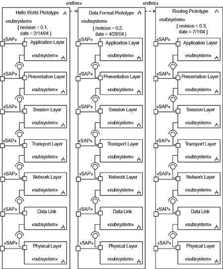
Each vertical slice implements only the portion of each layer relevant to the purpose of the slice. This approach to implementation is called iterative prototyping and each slice is called a prototype. The prototypes are implemented so that each prototype builds on the features implemented in its predecessors. The sequence of prototypes is decided based on which features logically come first as well as which represent the highest risk. With risk-based development, higher-risk items are explored and resolved as early as possible. This typically results in less rework and a more integrated, reliable system. Figure 8-16 shows a set of subsystems with a refinement relation between successive versions. The refinement relation is a stereotyped dependency in which one model element represents a more refined version of another. Also note that two tagged property values are used to indicate the version and date using the normal { tag = value} syntax. A more complete set of prototypes for Figure 8-16 might include those shown in Table 8-3.
Note how the later prototypes build on the services implemented in their predecessors. This is the essence of the iterative prototyping development philosophy gradually adding capability until the entire system is complete. Naturally, iterative prototyping applies to more than just communication protocol design. Any sufficiently complex piece of software can be broken down into a set of hierarchical layers in a client-server topology.[10]
It is common for these components to contain one or more threads. The concurrency model is another piece of architectural design that can greatly impact system performance. In a soft real-time environment, average throughput must be ensured, but individual deadlines are not crucial to system correctness. In hard real-time environments, however, each deadline must be met and the concurrency model must ensure the ability of the system to meet all deadlines. For most multitasking systems, this is a nontrival problem because the exact arrival patterns are not periodic and synchronous. Commonly, the system must respond to periodic events with vastly different periods as well as aperiodic events that may be bursty. Concurrency design is the subject of the latter half of this chapter. The last primary architectural goal is to design the global error handling policies to ensure correct system performance in the presence of faults.[11] Many strategies are possible, ranging from each object assuming full responsibility for all errors to a single global error handler that decides the correct action to take in all error conditions. Most systems are a hybrid of such approaches. One popular strategy is to have multiple levels of error handling with the general rule that each error will be handled at the point at which enough context is available to make the correct decision. An object with enough redundancy of its data members (such as triple storage for important data) might process an invalid data value by reconstructing the appropriate data value or assigning a default value in the event of an error. A subsystem might reboot itself and let the remainder of the system function when it discovers some particular error. Some errors may require a global handler to intervene and coordinate a correct system shutdown, such as in the event of a failure in a nuclear power plant.
Error handling policies are usually at least as complex as the primary software functionality and may result in systems three times as large and an order of magnitude more complex. Complicating error handling is the fact that it is highly system dependent, yet only through clear error handling policies can safety-critical systems be deployed safely.[12] This is an important aspect of the software architecture. [7] discusses the fundamental concepts of safety and reliability in the context of embedded system and [9] provides set of architectural design patterns for optimizing various aspects of system safety and reliability.
|
EAN: 2147483647
Pages: 127