11.3 Required Products of C4ISR
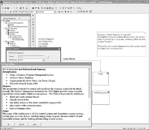
11.3 Required Products of C4ISRThe C4ISR-AF identifies a large number of artifacts, called products, that are used in the description of the various architecture views. Some of these are required for compliance to the C4ISR-AF, but most are optional and can be used when appropriate. These are referred to as supporting products. In this section, we discuss the required products listed in Table 11-1. 11.3.1 AV-1 Overview and Summary InformationThe Overview and Summary Information product is an essential artifact for making projects compliant with C4ISR-AF. [1] provides a list of the required contents of this artifact as well as a sample format. This information may be directly entered into the model in the model description field, as shown in Figure 11-1, or it may be created in a separate textual document and hyperlinked in the Rhapsody model. Figure 11-1. Report on Model for AV-1 Overview
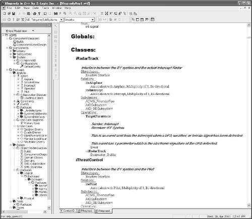
11.3.2 The AV-2 Integrated DictionaryThe Integrated Dictionary product defines the metadata of the product and is normally provided in a textual output. This metadata is maintained for you automatically by Rhapsody and may be viewed in the Rhapsody browser or used to generate reports and details as desired. This is illustrated in Figure 11-2. Besides the built-in report-on model, which can generate reports, Rhapsody has a powerful reporting facility known as ReporterPLUS, which allows you to generate reports in customizable formats and templates. Figure 11-2. AV-2 Integrated Dictionary
11.3.3 OV-1 High-Level Operational Concept GraphicThis is a very general architectural picture of the architecture-description products. It is used to facilitate human-human communication, especially among high-level decision makers. Commonly, it graphically depicts the coordinated deployment of systems to achieve the operational objectives. This is easily done in a class or deployment diagram, using stereotypes to identify the various kinds of systems involved in the operational concept. Figure 11-3 shows an example operational concept diagram as a class diagram using standard UML elements classes with appropriate stereotypes and dependency relations. Figure 11-3. OV-1 Operation Concept Diagram with Standard Notation
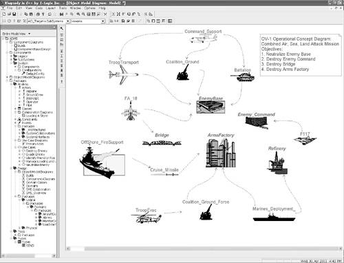
Figure 11-4 shows the same diagram using meaningful bitmap icons to represent the operational elements. This is very simple to do with Rhapsody and simplifies the interpretation of the graphic. Figure 11-4. OV-1 Operational Concept Diagram in Rhapsody with Icons
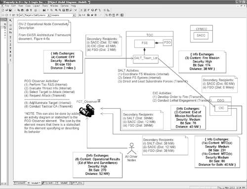
11.3.4 OV-2 Operational Node Connectivity DescriptionThe Operation Node Connectivity Description identifies the operational nodes, their connections, and the information shared among them. In the UML, operational nodes may be represented as classes on class diagrams or as nodes on deployment diagrams. In Figure 11-5,[2] operational nodes and subnodes are shown as classes; the interfaces among the operational nodes are mediated via the associations. The actual information content transmitted along these associations is captured in constraints (the notes with the curly braces), and supporting information is shown in either free text or comments within note boxes.
Figure 11-5. OV-2 Operational Node Connectivity with Classes
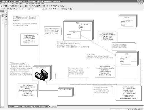
The same information is shown in the diagram in Figure 11-6, except that the operational nodes are shown as nodes on a deployment diagram. In general, classes have richer semantics than nodes on deployment diagrams and so are usually preferred for that reason. Figure 11-6. OV-2 Operational Node Connectivity with Deployment Diagram
11.3.5 OV-3 Operational Information Exchange MatrixThe Operational Information Exchange Matrix expresses the relationship between activities, operational elements, and information flow, focusing on the latter. The UML doesn't have a matrix notation, but this can be cast as a specialized format of a report constructed from the model repository held by Rhapsody. Alternatively, the data flow notation of the UML 2.0 can easily depict the information exchange among operational elements. In the UML diagram in Figure 11-7, icons are used to represent operational elements (modeled with UML classes) with information flows among these elements. Figure 11-7. OV-3 Data Information Exchange
11.3.6 SV-1 System Interface DescriptionThe System Interface Description shows the structural elements of the systems architecture and the informational interfaces among them. Sometimes it is important to show the large-scale deployment of the elements into the systems rather than their categories, as is shown in Figure 11-8. Figure 11-9 shows the deployed systems as structured classes with the internal subsystems as classes. These elements may have stereotypes attached, if desired. This more detailed view shows the subsystems and their interconnections within the systems as well as between systems. Figure 11-8. SV-1 System Interface Description
Figure 11-9. SV-1 Intrasystem Perspective
11.3.7 TV-1 Technical Architecture ProfileThe Technical Architecture Profile is a description of the technologies to be included in the system, normally as references to application standards documents, such as [1] or the POSIX standard. These may be specified in a textual document (most common) or they may be added as constraints to the model elements. |
EAN: 2147483647
Pages: 127