Windows-Based VPNs
| Microsoft Windows 2000, XP, and 2003 provide built-in support for IPSec VPN connectivity. The IPSec VPN implementation within the MS-Windows OS is based on the standard architecture described by IETF RFCs 2401 2409, thus allowing easy interoperability with various vendors. Netadmins can deploy a Windows machine as a VPN gateway to establish a site-to-site VPN with remote peers. The site-to-site VPN can use either IPSec with preshared keys (for small-scale deployment) or IPSec with CA (for large-scale deployment). Furthermore, the remote peer can be a Cisco router, PIX Firewall, or VPN 3000 concentrator. Table 10-10 lists the IPSec parameters supported by MS-Windows. Note that only Diffie-Hellman key exchange group 1 and group 2 are supported by Microsoft. An additional feature of the Windows OS is the support for MS Active Directory based Kerberos authentication for the IPSec peer.
Netadmins can leverage the Windows native IPSec support when deploying a site-to-site VPN, without paying for additional software. The following sections discuss VPN interoperability between MS-Windows and Cisco devices. Note MS-Windows has been the target of various network attacks. Additionally, Windows offers a plethora of features and services that can introduce additional vulnerabilities. To deploy a Windows-based VPN server that faces the Internet, always follow proper security recommendations and security best practices. Ensure that you do the following:
Windows/Cisco InteroperabilityConsider the network scenario shown in Figure 10-14. The two remote sites are connected to each other using an IPSec VPN tunnel through the Internet. The VPN gateway in site A is an MS-Windows (2000/XP/2003) based IPSec peer. The gateway in site B can be a Cisco IOS, PIX Firewall, or VPN 3000 concentrator acting as the IPSec peer. Figure 10-14. LAN-to-LAN VPN Establishing the VPN tunnel between the two remote sites uses the following two steps:
Deploying IPSec on WindowsDeploying an IPSec-based VPN on a Windows machine is a two-stage process. You first prepare the Windows machine according to certain prerequisites for its role as an IPSec-based VPN gateway. Next is the configuration of various IPSec parameters. After the IPSec server is configured and running, you can monitor the IPSec operation using built-in tools and utilities on the Windows machine. PrerequisitesBy default, Windows machines are not ready for their role as an IPSec VPN gateway. To configure a Windows machine as an IPSec server, certain prerequisites must be met. Following is a brief list of these requirements:
Caution Although site-to-site VPNs ease the administrative burden on the Netadmin, they are a security risk, because the remote LAN users have full access to the local resources. Netadmins must always scrutinize the risks involved and ensure that the local resources are well protected through firewalls, intrusion detection systems (IDSs), and other access-control mechanisms. ConfigurationTo configure a Windows IPSec VPN, follow these steps:
Note that each of these tasks must be carried out sequentially. All the steps are mandatory and must follow the order described in the following sections. Step 1: Create an IPSec PolicyThe steps used to create an IPSec policy on a Windows host are listed in Table 10-11.
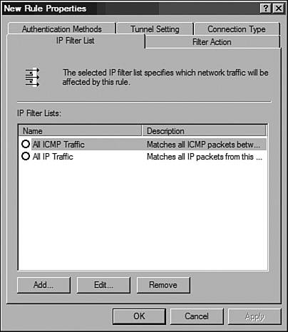
Figure 10-15. Windows IP Security Policy Management Snap-In Step 2: Identify Interesting Traffic Using Filter ListsWindows IPSec policy uses filter lists to identify traffic flowing in each direction. Hence, two filters are created for every IPSec tunnel: one for traffic destined for the remote LAN and a second for the traffic from the remote LAN. This task is similar to the mirrored access list used in IOS or PIX to define interesting traffic. The steps used to create filter lists for traffic flowing from site A to site B are listed in Table 10-12.
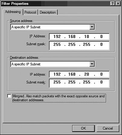
Figure 10-16. New Rule Properties Window Figure 10-17. Filter Properties Window The steps used to create filter lists for traffic flowing from site B to site A are listed in Table 10-13. The steps are similar to those discussed in the previous table, with one obvious exception: The source and destination addresses are reversed.
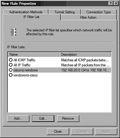
Figure 10-18. New Rule Properties Window Step 3: Configure Phase 2 ParametersWindows uses tunnel rules to define the phase 2 (IPSec SA) parameters. Because each IPSec tunnel is described by two unique one-way SAs, two rules should be configured. This task is roughly equivalent to creating crypto maps and transforms sets on Cisco devices. The steps used to configure a rule for the site A to site B tunnel SA are listed in Table 10-14.
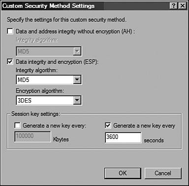
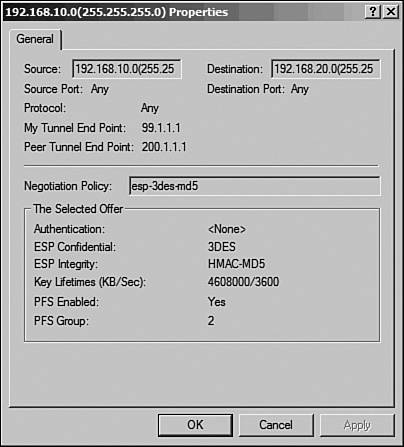
Figure 10-19. Custom Security Method Settings Window The steps used to configure a rule for the site B to site A tunnel SA are listed in Table 10-15.
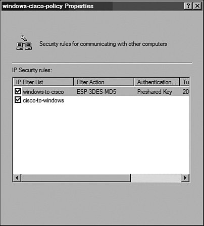
Figure 10-20. Policy Properties Window Step 4: Configure Phase 1 (IKE) ParametersThe IKE parameters for a Windows IPSec policy are configured through the General tab of the IPSec Policy Properties page. This task is similar to the crypto isakmp configuration for Cisco devices. The steps used to configure the IKE parameters are listed in Table 10-16.
Step 5: Assign the IPSec Policy to the Windows GatewayAfter the IPSec policy is configured, the policy should be assigned to the Windows VPN gateway. This task is similar to applying the crypto map on the interfaces of Cisco devices. To assign the new policy, right-click the new policy (for example, windows-cisco-policy) in the IP Security Policy Management MMC snap-in and then click the Assign button. A green arrow appears in the folder icon next to the policy. After the policy is assigned, the Windows machine is ready to act as a VPN gateway. Assuming that the remote peer is configured properly, the traffic between the two LANs will be protected by IPSec. A simple ping from one of the local hosts to a host in the remote LAN can verify the operation of the IPSec tunnel. Monitoring and TroubleshootingTo monitor and troubleshoot IPSec service in Windows, the most popular options are as follows:
Services ConsoleFor troubleshooting purposes, you might need to stop or restart IPSec services. Moreover, IPSec services must be restarted after making changes to the IPSec configuration. Stopping the IPSec services disables all the IPSec functionality and drops the existing IPSec sessions and tunnels. IPSec services are controlled through the Windows Services MMC snap-in console. The steps to restart IPSec services are as follows:
IP Security MonitorWindows provides built-in utilities for monitoring IPSec sessions. These tools provide details regarding the current phase 1 and phase 2 SAs that are established on the local Windows machine. The tools also provide IPSec and ISAKMP statistics that are helpful in troubleshooting IPSec issues. Windows 2000 provides the ipsecmon.exe utility to monitor the live IPSec activities. To launch ipsecmon.exe, choose Start > Run, enter ipsecmon.exe, and click the OK button. Windows XP and 2003 provide the IP Security Monitor console to monitor the current IPSec activities. Follow these steps to launch the IP Security Monitor console:
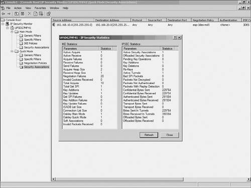
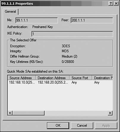
The IP Security Monitor console also displays the current Main Mode (phase 1) and Quick Mode (phase 2) details. To view the Main Mode SAs, navigate to Main Mode > Security Associations, as shown in Figure 10-22. Figure 10-22. Windows IPSec Main Mode The right pane shows the current Main Mode SAs. If the Main Mode negotiation between the IPSec peers fails, this window will be empty. Double-click the SA to view the details, as shown in Figure 10-23. Figure 10-23. Windows IPSec Main Mode Details Similarly, Figure 10-24 shows the details of an SA established in Quick Mode. The Quick Mode SAs are only displayed after the peers successfully negotiate phase 2. Figure 10-24. Windows IPSec Quick Mode Statistics Additionally, the details of both Main and Quick Mode SAs display the IP addresses of the local (source) and remote (destination) LANs. This information can verify that IPSec is indeed tunneling the traffic as configured. Event ViewerTo enable IPSec services logging the IKE and IPSec negotiations in the Windows Event Viewer, use the Local Policy MMC snap-in by following these steps:
The IPSec logs can be viewed in the Security section of the Windows Event Viewer. Caution The IKE process creates a large number of audit logs. To disable IKE logs, create the following registry key and set its value to 1: HKEY_LOCAL_MACHINE\System\CurrentControlSet\Control\Lsa\Audit\DisableIKEAudits Deploying IPSec on Cisco DevicesThe configurations for Cisco PIX Firewalls, IOS, and VPN concentrators are similar to those discussed in the section "Linux-Based VPNs," earlier in this chapter; the Diffie-Hellman group identifier is the only exception. Because MS-Windows only supports D-H groups 1 and 2, the configuration for Cisco devices should be modified to use D-H group 2 and PFS group 2. The following are partial configurations for Cisco devices:
Example 10-18. IOS Partial Configuration for IPSecCisco-rtr#show running-config ! Phase 1 configuration crypto isakmp policy 3 encr 3des hash md5 authentication pre-share ! MS-Windows only support DH group 1 & 2 group 2 crypto isakmp key cisco123 address 99.1.1.1 !Phase 2 Configuration crypto ipsec transform-set myset esp-3des esp-md5-hmac ! crypto map vpn 30 ipsec-isakmp set peer 99.1.1.1 set transform-set myset ! MS-Windows only support DH group 1 & 2 ! set pfs group2 match address 100 ! interface Ethernet0/0 ip address 192.168.20.1 255.255.255.0 ! interface Serial0/0 ip address 200.1.1.1 255.255.255.252 crypto map vpn ! ip route 0.0.0.0 0.0.0.0 200.1.1.2 ! access-list 101 permit ip 192.168.20.0 0.0.0.255 192.168.10.0 0.0.0.255 ! end Example 10-19. PIX Partial Configuration for IPSecPIX-FW# show running-config hostname PIX-FW domain-name VPNtest.com access-list 101 permit ip 192.168.20.0 255.255.255.0 192.168.10.0 255 .255.255.0 access-list 102 permit ip 192.168.20.0 255.255.255.0 192.168.10.0 255 .255.255.0 ip address outside 200.1.1.1 255.255.255.0 ip address inside 192.168.20.1 255.255.255.0 global (outside) 1 interface nat (inside) 0 access-list 102 nat (inside) 1 0.0.0.0 0.0.0.0 0 0 access-group 120 in interface outside route outside 0.0.0.0 0.0.0.0 200.1.1.2 1 sysopt connection permit-ipsec crypto ipsec transform-set myset esp-3des esp-md5-hmac ! crypto map mymap 10 ipsec-isakmp crypto map mymap 10 match address 101 ! MS-Windows only support DH group 1 and 2 crypto map mymap 10 set pfs group2 crypto map mymap 10 set peer 99.1.1.1 crypto map mymap 10 set transform-set myset crypto map mymap interface outside ! Define IKE parameters ! isakmp enable outside isakmp key ******** address 99.1.1.1 netmask 255.255.255.255 isakmp identity address isakmp policy 10 authentication pre-share isakmp policy 10 encryption 3des isakmp policy 10 hash md5 ! MS-Windows only support DH group 1 and 2 isakmp policy 10 group 2 isakmp policy 10 lifetime 86400 : end Example 10-20. VPN 3000 Partial Configuration for IPSecIKE proposal: Configuration > Tunneling and Security > IPSec > IKE Proposals > Add. Proposal Name = Proposal-1 Authentication Mode = Preshared Keys Authentication Algorithm = MD5/HMAC-128 Encryption Algorithm = 3DES-168 !---Windows supports Diffie-Hellman group 2 Diffie Hellman Group = Group 2 (1024-bits) Lifetime Measurement = Time Date Lifetime = 10000 Time Lifetime = 86400 Define the LAN-to-LAN tunnel: Configuration > Tunneling and Security > IPSec > LAN- to-LAN > Add.: Enabled= checked Name = new-vpn Interface = Ethernet 2 (Public) (200.1.1.1) Connection Type= Bi-directional Peer = 99.1.1.1 Digital Certs = none (Use Pre-shared Keys) Pre-shared key = cisco123 Authentication = ESP/MD5/HMAC-128 Encryption = 3DES-168 IKE Proposal = Proposal-1 Filter= --None-- IPSec NAT-T= unchecked Bandwidth Policy= --None-- Routing= --None-- ! Local Network Network List = Use IP Address/Wildcard-mask below IP Address= 192.168.20.0 Wildcard Mask = 0.0.0.255 ! Remote Network Network List = Use IP Address/Wildcard-mask below IP Address= 192.168.10.0 Wildcard Mask= 0.0.0.255 Security Association: Configuration > Policy Management > Traffic Management > SAs > L2L:new-vpn > Modify. SA Name = L2L: new-vpn Inheritance = From Rule ! IPSec Parameters Authentication Algorithm = ESP/MD5/HMAC-128 Encryption Algorithm = 3DES-168 Encapsulation Mode = Tunnel !---Windows supports Diffie-Hellman group 2 PFS = Group2 (1024-bits) Lifetime Measurement = Time Data Lifetime = 10000 Time Lifetime = 28800 ! IKE Parameters Connection Type= Bidirectional IKE Peer = 99.1.1.1 Negotiation Mode = Main Digital Certificate = None (Use Preshared Keys) Certificate Transmission= Identity certificate only IKE Proposal= Proposal-1 |
EAN: 2147483647
Pages: 106