Configuring Cisco Devices to Use a Syslog Server
| Most Cisco devices use the syslog protocol to manage system logs and alerts. But unlike their PC and server counterparts, Cisco devices lack large internal storage space for storing these logs. To overcome this limitation, Cisco devices offer the following two options:
Tip Before configuring a Cisco device to send syslog messages, make sure that it is configured with the right date, time, and time zone. Syslog data would be useless for troubleshooting if it shows the wrong date and time. You should configure all network devices to use NTP. Using NTP ensures a correct and synchronized system clock on all devices within the network. Setting the devices with the accurate time is helpful for event correlation. To enable syslog functionality in a Cisco network, you must configure the built-in syslog client within the Cisco devices. Cisco devices use a severity level of warnings through emergencies to generate error messages about software or hardware malfunctions. The debugging level displays the output of debug commands. The Notice level displays interface up or down transitions and system restart messages. The informational level reloads requests and low-process stack messages. Configuring Cisco Routers for SyslogTo configure a Cisco IOS-based router for sending syslog messages to an external syslog server, follow the steps in Table 4-11 using privileged EXEC mode.
Note When a level is specified in the logging trap level command, the router is configured to send messages with lower severity levels as well. For example, the logging trap warning command configures the router to send all messages with the severity warning, error, critical, and emergency. Similarly, the logging trap debug command causes the router to send all messages to the syslog server. Exercise caution while enabling the debug level. Because the debug process is assigned a high CPU priority, using it in a busy network can cause the router to crash. Example 4-12 prepares a Cisco router to send syslog messages at facility local3. Also, the router will only send messages with a severity of warning or higher. The syslog server is on a machine with an IP address of 192.168.0.30. Example 4-12. Router Configuration for SyslogRouter-Dallas# Router-Dallas#config terminal Enter configuration commands, one per line. End with CNTL/Z. Router-Dallas(config)#logging 192.168.0.30 Router-Dallas(config)#service timestamps debug datetime localtime show-timezone msec Router-Dallas(config)#service timestamps log datetime localtime show-timezone msec Router-Dallas(config)#logging facility local3 Router-Dallas(config)#logging trap warning Router-Dallas(config)#end Router-Dallas#show logging Syslog logging: enabled (0 messages dropped, 0 flushes, 0 overruns) Console logging: level debugging, 79 messages logged Monitor logging: level debugging, 0 messages logged Buffer logging: disabled Trap logging: level warnings, 80 message lines logged Logging to 192.168.0.30, 57 message lines logged Configuring a Cisco Switch for SyslogTo configure a Cisco CatOS-based switch for sending syslog messages to an external syslog server, use the privileged EXEC mode commands shown in Table 4-12.
Example 4-13 prepares a CatOS-based switch to send syslog messages at facility local4. Also, the switch will only send messages with a severity of warning or higher. The syslog server is on a machine with an IP address of 192.168.0.30. Example 4-13. CatOS-Based Switch Configuration for SyslogConsole> (enable) set logging timestamp enable System logging messages timestamp will be enabled. Console> (enable) set logging server 192.168.0.30 192.168.0.30 added to System logging server table. Console> (enable) set logging server facility local4 System logging server facility set to <local4> Console> (enable) set logging server severity 4 System logging server severity set to <4> Console> (enable) set logging server enable System logging messages will be sent to the configured syslog servers. Console> (enable) show logging Logging buffered size: 500 timestamp option: enabled Logging history size: 1 Logging console: enabled Logging server: enabled {192.168.0.30} server facility: LOCAL4 server severity: warnings(4 Current Logging Session: enabled Facility Default Severity Current Session Severity ------------- ----------------------- ------------------------ cdp 3 4 drip 2 4 dtp 5 4 dvlan 2 4 earl 2 4 fddi 2 4 filesys 2 4 gvrp 2 4 ip 2 4 kernel 2 4 mcast 2 4 mgmt 5 4 mls 5 4 pagp 5 4 protfilt 2 4 pruning 2 4 radius 2 4 security 2 4 snmp 2 4 spantree 2 4 sys 5 4 tac 2 4 tcp 2 4 telnet 2 4 tftp 2 4 udld 4 4 vmps 2 4 vtp 2 4 0(emergencies) 1(alerts) 2(critical) 3(errors) 4(warnings) 5(notifications) 6(information) 7(debugging) Console> (enable) Configuring a Cisco PIX Firewall for SyslogProactive monitoring of firewall logs is an integral part of a Netadmin's duties. The firewall syslogs are useful for forensics, network troubleshooting, security evaluation, worm and virus attack mitigation, and so on. The configuration steps for enabling syslog messaging on a PIX are conceptually similar to those for IOS- or CatOS-based devices. To configure a Cisco PIX Firewall with PIX OS 4.4 and above, perform the steps shown in Table 4-13 in privileged EXEC mode.
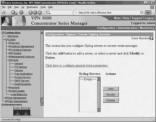
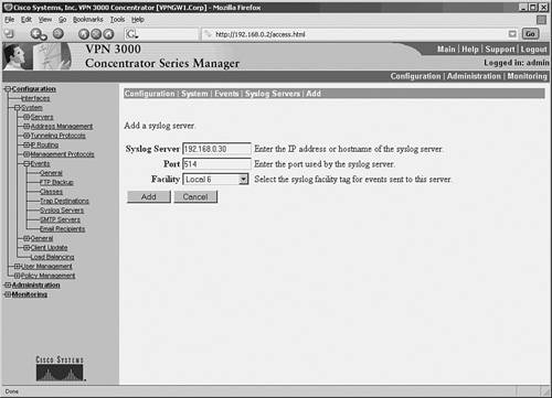
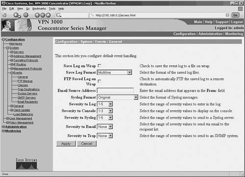
Example 4-14 prepares the Cisco PIX Firewall to send syslog messages at facility local5 and severity debug and below to the syslog server. The Netadmin does not want the PIX to log message 111005. The syslog server has an IP address of 192.168.0.30. Example 4-14. Configuring a Cisco PIX Firewall for SyslogFirewall-Dallas# Firewall-Dallas# config terminal Firewall-Dallas(config)# loggin time Firewall-Dallas(config)# logging host 192.168.0.30 Firewall-Dallas(config)# logging facility 21 Firewall-Dallas(config)# logging trap 7 Firewall-Dallas(config)# logging on Firewall-Dallas(config)# no logging message 111005 rewall-Dallas(config)# exit Firewall-Dallas# show logging Syslog logging: enabled Facility: 21 Timestamp logging: enabled Standby logging: disabled Console logging: disabled Monitor logging: disabled Buffer logging: disabled Trap logging: level debugging, 6 messages logged Logging to inside 192.168.0.30 History logging: disabled Device ID: disabled For added reliability, the Cisco PIX Firewall can be configured to send syslog messages through TCP. Please note that if the syslog server disk is full, it can close the TCP connection. This will cause a denial of service because the Cisco PIX Firewall will stop all traffic until the syslog server disk space is freed. Both Kiwi Syslogd Server and PFSS offer this feature. Kiwi Syslogd has an alert mechanism to warn the Netadmin through e-mail or pager when the disk is nearing its capacity. The setting can be established from the Syslog Daemon Setup window, as shown in Figure 4-9, for Kiwi syslog configuration. If the PIX stops because of a disk-full condition, you must first free some disk space. Then disable syslog messaging on the PIX by using the no logging host host command, followed by reenabling syslog messaging using the logging host host command. Caution The change in facility level for a particular message in the previous example is for illustration purposes only. Changing the facility level from its default value is an advanced Netadmin function and is strongly discouraged. Example 4-15 shows the configuration steps for a Cisco PIX Firewall to send syslog messages at TCP port 1468. Example 4-15. PIX Configuration for TCP SyslogFirewall-Dallas# config terminal Firewall-Dallas(config)# logging host inside 192.168.0.30 tcp/1468 Firewall-Dallas(config)# exit Firewall-Dallas# show logging Syslog logging: enabled Facility: 21 Timestamp logging: enabled Standby logging: disabled Console logging: disabled Monitor logging: disabled Buffer logging: disabled Trap logging: level debugging, 12 messages logged Logging to inside 192.168.0.30 tcp/1468 History logging: disabled Device ID: disabled Firewall-Dallas# Caution A Cisco PIX Firewall facing the Internet is subjected to a large amount of unsolicited traffic in the form of ping scans, port scans, and probes. This can cause the log file to become large within days. It will be filled with data, making it difficult to search for useful information. You should fine-tune your firewall to suppress certain common messages using the no logging message message-id-number command. Additionally, use the IOS firewall features on the edge router to filter unwanted traffic before it hits the Cisco PIX Firewall. Configuring a Cisco VPN Concentrator for SyslogThe Cisco VPN 3000 Series Concentrator provides an appliance-based solution for deploying VPN functionality across remote networks. VPN concentrators are often connected parallel to the firewalls, as shown earlier in Figure 4-1. The design simplifies the management of the network but creates security concerns. After a user has been authenticated through VPN concentrators, the user has complete access to the network. This makes a strong case for logging the messages from the VPN concentrator. To configure the Cisco VPN 3000 Series Concentrator for sending syslog messages, follow these steps:
As configured in this example, the VPN concentrator is now ready to send syslog messages at facility local6, severity 1 5 to server 192.168.0.30. |
EAN: 2147483647
Pages: 106