Layer 1 and Layer 2
| Many service providers implement MANs by using Synchronous Optical Network (SONET) or Ethernet. SONET is a physical layer standard, and is described later in this chapter. It provides more bandwidth than Ethernet, and supports multiple Layer 2 technologies, such as ATM, IP, and even Ethernet. Ethernet, as a standalone solution, is used typically for the following reasons:
Cisco Metro SolutionsCisco sells many metro solutions. Actually, many of the products that you would find at the distribution and core layers of an enterprise network are considered candidates for metro products for MANs. Table 11.1 compares some of Cisco's different metro solutions. As you can see from this table, Cisco provides both Catalyst switch and router solutions. Routers are sometimes used when complex queuing mechanisms are required or when you already have a router in place that performs the connectivity job adequately.
ServicesEthernet is set up over SONET services by carriers that offer MAN services. Carriers use SONET because of its flexibility in its capability to transport multiple services, such as Ethernet and ATM, and because of its ability to reach across long distances. For a company that has a large Ethernet infrastructure, this makes it easy to extend Ethernet connectivity across a carrier's network to other remote sites. This can be done using either routers or switches. For smaller companies, this reduces the number of Layer 3 devices that you need because Layer 2 Ethernet switches can be used for the MAN connections. Therefore, you don't need to deploy a separate router for each site, but deploy them only where they're necessary. When using Ethernet as a MAN solution, you should consider the following five items:
One of the foremost items you should consider is how cost effective an Ethernet service is for MAN connectivity. When evaluating costs, you should examine both the equipment costs as well as the ongoing connection and maintenance costs. The second thing you should consider is scalability. Scalability is not an issue when you're connecting a small number of sites together across a MAN. However, you should weigh how scalable a service provider's solution is if your network is dynamic and/or growing. From a dynamic perspective, how easy and quick is it to connect to the carrier? How fast can the service provider change services for you if your bandwidth needs change? The third item you should consider is transparency. One of the main reasons customers enjoy Ethernet services in a MAN environment is that the MAN is treated as a transparent network it's invisible to the customers' equipment, whether the equipment be a switch or a router. In other words, the service provider creates a logical connection between two or more peering devices. From the customer's perspective, it appears that the equipment is directly connected together via the same physical layer connection. If you want multiple devices (Layer 2 or Layer 3) to appear to be on the same segment, the service provider makes it appear that these devices are connected via a hub even though the carrier is typically using other methods to provide for this connectivity. The fourth item you should consider is level of service. As you saw in Chapter 9, "Quality of Service," Cisco's switches can support a level of service infrastructure, favoring some types of traffic over others by enforcing Quality of Service (QoS) policies. Based on the behavior and needs of your traffic, you should consider a service provider that can meet these needs. The last item you should consider is the type of connection that you'll need across the MAN. There are two basic types of connections: point-to-point and multipoint. Point-to-point connections are very common in WAN and MAN environments because they are simple to set up for the service provider. However, there might be situations in which you want the provider's network to appear as a hub, where all your edge MAN devices appear to be directly connected together. If this is the case, you'll need to choose a MAN provider that can deal with issues such as trunking between devices as well as maintaining your STP topology both of these issues should be dealt with transparently by the service provider. The next section covers the two different services that providers use for these connections:
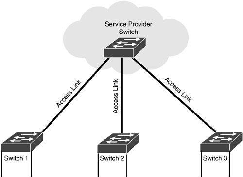
Transparent LAN ServicesWith transparent LAN services (TLS), the connection between switches in the MAN is done transparently by the service provider. In other words, the provider's equipment is hidden from your equipment's view. For example, let's look at the network in Figure 11.1. In this example, your switches have an access link connection to the carrier's network, and all of these connections are in the same VLAN. The switches don't actually see the service provider's switch; instead, it appears that all of your switches are connected together via a hub. Figure 11.1. Transparent LAN service.
Because of this structure, TLS is simple to implement from the carrier's side. From your side, you need only an access link connection and place the devices connected to the MAN in the same VLAN (subnet/broadcast domain). When implementing TLS, you should remember that your MAN connection is an access link. Therefore, for traffic to traverse the MAN, you must put all of your sites in the same VLAN, which doesn't scale from a broadcast perspective. This is especially true if you have a lot of multimedia applications that generate a lot of multicast traffic, such as real-time video. You could also break up the single-VLAN implementation into multiple VLANs by using a router at one or more sites to route traffic between the VLANs. If you have only one router, located at one site, to handle inter-VLAN traffic, it could cause a broadcast and multicast problem on the MAN because most inter-VLAN traffic will have to traverse the MAN to reach the router. This can be solved by placing a router at each site, which obviously increases costs. In addition, with a router at each MAN site, you might experience Layer 3 peering problems with certain routing protocols, such as OSPF. A third problem with TLS is that because you're using an access link connection to the provider, the provider has to associate all of your devices by placing them in a provider's VLAN. This is used to separate your traffic from other customer's traffic. However, one serious limitation that the service provider faces is the number of VLANs that its switches can support. With 802.1Q, the VLAN limit is 4,096. Therefore, the service provider wouldn't be able to support more than 4,096 customers with this implementation. 802.1Q functions at Layer 2. Multiprotocol label switching (MPLS) also allows tunneling if information crosses a carrier's backbone. MPLS functions at Layer 3. Both solutions are covered later. However, even given these problems, TLS does have a place in a network design. If you have only a small number of sites that need to be connected and not much traffic is sent between sites, TLS provides an excellent fit.
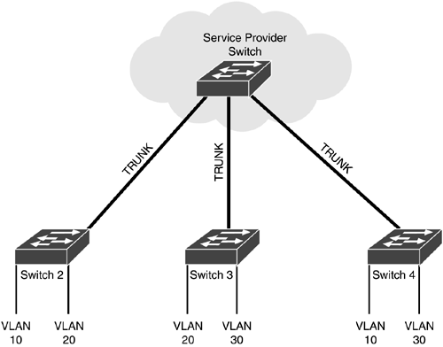
Directed VLAN ServicesWith a directed VLAN service (DVS), the edge switches connect to the carrier via a trunk link. From the edge switch's perspective, it knows that it is connecting to a service provider switch and is setting up a trunk connection to the carrier's switch, as shown in Figure 11.2. Connections by the carrier can be set up as either point-to-point or multipoint. Figure 11.2. Directed VLAN service.
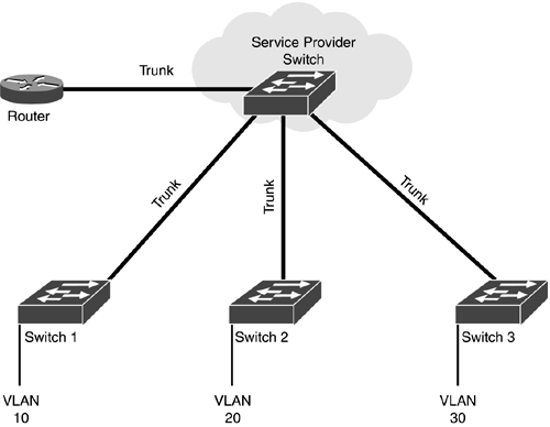
You can use two basic design approaches for connectivity: put a router at a single location for inter-VLAN routing, or put a router at each location. Because DLS uses trunks, it's safe to assume that you have multiple VLANs in your network. Therefore, you'll need some type of Layer 3 device to handle inter-VLAN traffic. If you have a router at only a single location, inter-VLAN traffic from other sites will have to travel across the MAN to be routed, as shown in Figure 11.3. This is an example of a hub-and-spoke design. Figure 11.3. Directed VLAN service and a single router.
In this example, for VLAN 1 off of Switch1 to reach VLAN 2 off of Switch2, the traffic must be sent across the MAN to the router to be routed. Plus, broadcast traffic that occurs at remote sites will have to traverse the MAN. For example, a broadcast in VLAN 1 will be sent to all your devices connected to the MAN: the router, Switch1, Switch2, and Switch3. For multicast traffic, this can seriously affect your performance. If you place a router at each site, you're increasing your equipment costs. Therefore, you'll have to look carefully at your traffic characteristics when deciding how many routers you should purchase and the location(s) at which they should be installed. One concern with DVS is that the carrier switch that is connected to your switch must know what VLANs are being used in your network so that PVST+ and pruning can be implemented efficiently. This brings up a problem: If a carrier's network supports only 4,096 VLANs with 802.1Q, and each customer has about 100 VLANs, only 40 customers could be supported in the carrier's network. From a carrier's point-of-view, this is even more limiting than TLS. However, as you'll see later in this chapter, Cisco can tunnel 802.1Q trunking information between two sites. This allows the carrier switches to tunnel your VLAN information inside the carrier's tagged frames, which enables the carrier to keep different customers' traffic separate while still maintaining the VLAN infrastructure you've built for your own network.
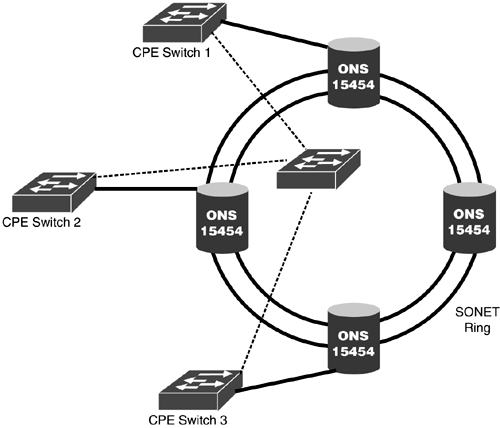
Delivery MechanismsWhen a service provider designs a MAN solution, the physical layer contains fiber cabling. Actually, there are many solutions that the carrier could use on the fiber cabling to transport Ethernet between a customer's various sites. However, the carrier typically doesn't use a physical layer implementation of Ethernet. Instead, the carrier will use SONET, dense wave division multiplexing (DWDM), or coarse wave division multiplexing (CWDM). The following sections briefly cover these three implementations. Ethernet over SONETThere are two main standards for transmitting signals across fiber: SONET (Synchronous Optical Network) and SDH (Synchronous Digital Hierarchy). SONET is defined by the Exchange Carriers Standards Association (ECSA) and American National Standards Institute (ANSI) and is used in North America. SDH is an international standard and is used throughout most of the world. Both standards define the physical layer framing used to transmit light sources. SONET can be used to transport Ethernet frames. Physically, SONET uses a ring topology, as shown in Figure 11.4. Actually, a dual-ring topology is used to provide redundancy. This is similar to FDDI's dual-ring implementation. Unlike in Ethernet, fault protection is built into SONET, providing less than a 50ms cutover when a failure takes place in the MAN. Cisco ONS 15454 devices can be used to build the SONET ring. They're popular among carriers because the ONS 15454 devices support both Ethernet and SONET interfaces and can provide time division multiplexing (TDM) and DWDM solutions. The ONS product supports multiplexing, optical networking, and switching networking elements all in one chassis. Figure 11.4. SONET connections.
In the example shown in Figure 11.4, the solid lines indicate the physical connections, and the dotted lines indicate the logical connections. Notice that from the customer premise equipment (CPE) switch's perspective, it looks like a hub-and-spoke design, with a provider switch in the middle. Cisco's ONS 15454 switches can provide 802.1Q trunk or access link connections to the user, and transfer Ethernet frames around the ring using SONET. SONET is generally available in MAN services, supports multiple connection types (such as Ethernet, ATM, IP, and leased circuits), and has built-in redundancy. However, SONET does have its drawbacks. It supports bandwidth only in increments of 51.84 Mbps, which is typically too much bandwidth for a customer. This results in poor bandwidth usage by the provider. In addition, SONET was not developed for carrying Ethernet traffic: It was developed for low-speed voice connections. Also, as part of its redundancy mechanism, one ring sits idle, which is a waste of bandwidth.
Ethernet over DWDMDWDM, like SONET, runs over fiber. However, the similarities between SONET and DWDM radically diverge from this point. DWDM is an enhancement of wave division multiplexing (WDM). One of the main issues of SONET, as mentioned in the last section, is that bandwidth is associated in blocks of 51.84Mbps. This is not very efficient in carrier networks that have more data traffic than voice traffic. WDM deals with this issue by using a wavelength frequency to transmit information. Multiple connections can be used on the same fiber by assigning them a different wavelength frequency. With WDM, you're somewhat limited in the number of frequencies and, therefore, the number of connections. DWDM extends this number to more than 200 frequencies. One advantage of using a frequency rather than the time-division multiplexing (TDM) technique that SONET uses is that you are no longer constrained to blocks of 51.84Mbps of bandwidth. As a carrier, you can be more granular in allotting bandwidth to customers. Two transmissions are used with DWDM: 1310 nanometer and 1550 nanometer (nm). These transmissions refer to the gap in wavelengths. 1310 transmissions are more popular in short-distance environments, such as MANs, because of their lower cost. 1550 transmissions cost more, but can span larger distances. Both types of transmission support redundancy. With DWDM, point-to-point connections are built between sites. The CPE typically connects via Fast or Gigabit Ethernet to the carrier, and the carrier uses an optical switch to convert the Ethernet frames into a wavelength frequency. From the CPE's perspective, it appears that the two devices connected via the MAN are really directly connected to each other via a point-to-point Ethernet connection. And because point-to-point connections are used, as long as you use a hub-and-spoke design (no Layer 2 loops), you should not have to deal with STP issues across the MAN. Cisco supports two DWDM products: ONS 15200 and ONS 15540. Cisco's product provides the following advantages: it has a low cost for connecting to buildings with a small number of customers; it doesn't require Gigabit Ethernet connectivity within the carrier's network; and it is easy to install, test, and maintain. DWDM's advantages include high data rates (Gbps) and scalability, easy setup, transparency to the CPE, and optical protection (similar to SONET). However, DWDM needs its own fiber connection and cannot run over SONET. Therefore, if you're already using a SONET connection for voice and want to integrate data, you'll have to do it on different fiber cable. In that situation, you'll need to hope that the carrier has some spare dark fiber for your data connection. Dark fiber is extra fiber that the carrier has run, but is not currently using. Ethernet over CWDMCWDM is a last-mile technology. That means the service provider typically uses CWDM from its switches to the customer, and not for its backbone technology. CWDM, which cannot be optically amplified, has a much shorter operating distance than DWDM and is very cost-effective for connecting a small number of customers in a small area.
CWDM uses optical add/drop multiplexors (mux) to provide for the physical ring topology. These multiplexors are connected to the ring and the customer's equipment is then connected to the multiplexor. Instead of deploying expensive 10Gb Ethernet connections that would require DWDM, CWDM enables you to deploy multiple 1Gb Ethernet connections that you can form into an EtherChannel. CWDM is supported by the Catalyst 6500, 4000, 3550, and 2950 switches as well as the ONS 154xx and 153xx optical switches. Cisco switches support 8 CWDM wavelengths.
|
EAN: 2147483647
Pages: 171