Map View
| Cisco Security Manager features an easy-to-use topology map to manage a network, including networks that are self-defending. Several default background maps are provided, and a customization feature enables users to create their own background map on the topology by importing a JPG, BMP, or GIF file. To access a topology map, click the Map View icon, which is the second icon on the left and next to the Device View icon on the main homepage. Figure 9-14 displays an example of how to launch the map view. Figure 9-14. Launch Map View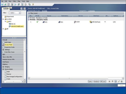 Figure 9-15 displays a sample topology map background. Cisco Security Manager uses a right-click methodology like many other Windows applications. The drop-down list that appears by right-clicking directly on the topology map enables you to add a device or change the background map. Figure 9-15. Topology Map Background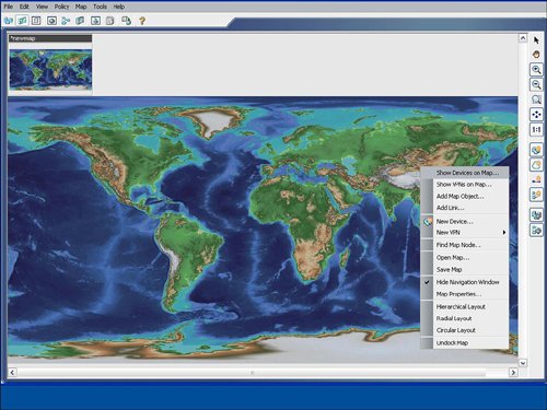 As you learn in the next sections, devices and other nodes like networks and hosts can be added to the topology map. You also learn how to configure a firewall from the topology map. Showing Devices on the Topology MapCisco Security Manager provides a mechanism to easily add devices from device groups to the topology map. Users can right-click on the topology map to show a device to the topology map by using the Device Selector option from the drop-down menu after the right-click select. The show device feature for a topology map involves displaying a device that is already imported into the Cisco Security Manager. The New Device option is designed to add or import a new device into Cisco Security Manager directly through a topology map. Figure 9-16 displays an example of showing a device on the topology map by selecting the Show Devices on Map option. The user may manually place the device at the desired location on the map, for example a security appliance at the Wall Street office may be placed in the NYC region on the map. The show device option will also add the networks that are directly connected to each interface on the device to the topology map. Figure 9-16. Show Device on the Topology Map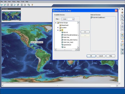 Adding Cloud Networks and Hosts to the Topology MapThe Cisco Security Manager examines the interface IP addresses to determine if devices are located on the same subnet. As shown in Figure 9-17, the Cisco Security Manager features the Add Link icon on the right side of the map to draw the connections between devices on the map. If the user tries to add a link between two managed devices on the map that are not on the same subnet, the Cisco Security Manager will create a cloud network between the devices to indicate that the devices are not on the same subnet. Figure 9-17. Create a Link Between Devices on the Topology Map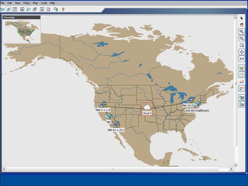 The process to manually add additional networks and hosts to the topology map is initiated by selecting the Add Map Objects to Map icon on the right-hand side of the topology map. Networks and hosts can be manually defined, or they can be selected from existing network objects. Network objects can be used in the access control list (ACLs) rule table and in other configuration options in the Cisco Security Manager. Hosts are typically nonmanaged devices to the Cisco Security Manager and can be added to a topology map to help create a visual picture of the management and critical resources in the self-defending network. Configuring Firewall Access Control List (ACLs) Rules from Topology MapThe "Device View" section of this chapter detailed how to add an access control list (ACLs) to a device from the device view. You can also configure access control list (ACLs) rules on a firewall device from a topology map in the map view. The topology map view is a good fit for smaller networks or for security or network operators who prefer to view their network graphically with a topology map. In addition to smaller networks, topology maps can also be a good fit for the commercial or smallmedium business customers. From the topology map, a user can select a firewall by right-clicking it and then select the firewall access control list (ACLs) option for it. Figure 9-18 provides an example of how right-clicking the ASA-NYC-WallStreet1 firewall icon enables the user to select the access-rules configuration option for that device. Figure 9-19 displays an example of the rule table for that firewall. The access control list (ACLs) rule table for the device that is launched from the topology map is identical to the access control list (ACLs) rule table that is displayed for the device in the device view, as discussed previously in this chapter. Users can display, add, edit, or delete access control list (ACLs) rules for a device directly from the topology map. Users can also access the advanced functions of the access control list (ACLs) rule table, including policy query, rule analysis, and access control list (ACLs) hit count. Figure 9-18. Configure Access Control List (ACLs) Rules from the Topology Map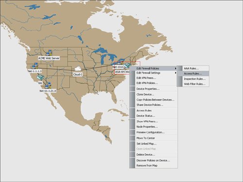 Figure 9-19. Access Control List (ACL) Rule Table for Device from the Topology Map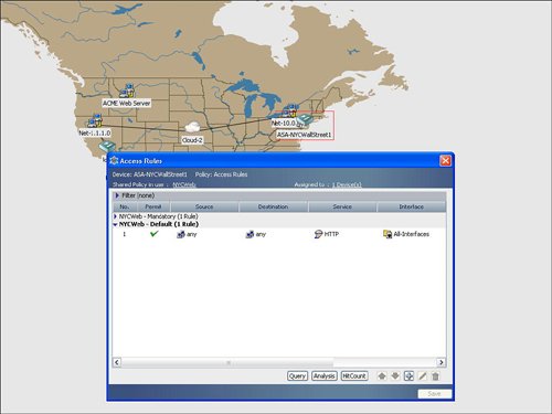 |
EAN: 2147483647
Pages: 112