Chapter 5: IP Location in Enterprise Networks
Chapter 4 described how an IP device might learn its location using the HELD protocol. In an enterprise network, the HELD protocol is not the only candidate for location acquisition; DHCP and LLDP-MED, described briefly in Chapter 1, also have a role to play. This chapter is broken into five parts: enterprise network access technology overview, location determination in enterprise networks, location acquisition in enterprise networks, enterprise location considerations, and enterprise location applications.
Enterprise Network Access Technologies
Enterprise networks are diverse. They can be large or small, flat or hierarchical, contiguous or disjointed, wireless or wired-the list goes on and on. There is no standard for what constitutes an enterprise network, consequently the technologies and mechanisms that are needed to determine location also vary from network to network. This section describes two enterprise access technologies and configurations.
Wired Ethernet Networks
Wired Ethernets are used extensively in Enterprise networks and can be configured and connected in a multitude of ways. Networks are constructed to keep interswitch and internetwork traffic to a minimum so as to optimize network performance. This is done by placing frequently communicating machines on the same switch or stack of switches. Where this is not possible, switches may be cascaded together and VLANs introduced to keep different LAN streams on the same switch separated.
IP addresses may be statically configured, or as is generally the case, provided dynamically using the Dynamic Host Configuration Protocol (DHCP) as described in Reference 1 at the end of the chapter, by a DHCP server. Increasingly, DHCP servers are becoming centralized functions requiring DHCP messages to transit several subnets. This requirement poses some problems to hosts needing dynamically allocated DHCP IP addresses since service discovery in DHCP is performed using IP broadcast messages that are blocked by IP routing functions to prevent network packet storms and worse.
This situation was addressed in the forerunner protocol to DHCP, BOOTP in Reference 2, through the use of agents, referred to in the common vernacular as relay-agents. A relay-agent generally resides in an IP gateway function (router) and intercepts DHCP broadcast traffic. The relay-agent directs the intercepted traffic to the DHCP server on behalf of the requesting node using unicast IP. In other words, the relay-agent knows the IP address of the DHCP server and is inherently trusted by it; a DHCP client has no visibility of the presence of the relay-agent. The functionality that a relay-agent can provide has grown over time, with the foundation for much of this functionality being defined in Reference 3, the DHCP Relay Information Option. The general purpose of many of the DHCP relay functions is to provide additional information to the DHCP server to aid it in making decisions about what network configuration values to provide to a host. It also happens that some of this information can aid in location determination, as will be seen later.
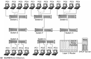
Traditionally, edge switches such as those shown in Figure 5.1 (switches A, B, C, D, and G) were relatively simple devices providing traffic separation through VLAN configurations. Edge Ethernet switches are becoming increasingly sophisticated with many offering advanced IP routing functionality such as Access Control Lists and DHCP relay functionality.

Figure 5.1: Wired Ethernet.
WiFi Networks
The 802.11 suite of protocols (a, b, g), collectively referred to as WiFi, provide wireless connectivity to a LAN. Speeds and QoS options vary from flavor to flavor, with 802.11g being commonly deployed and providing an access bandwidth of 54 Mbps. WiFi networks can be configured and rolled out in a number of ways. Such networks consist of standalone wireless access points (WAPs) and wireless network controller (WNC) configurations, discussed next.
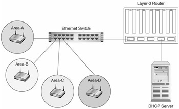
The simplest form of WiFi network consists of one or more WAPs connected to a standard Ethernet switch, which in turn is connected to an intranet containing a DHCP server and other layer-3 routing infrastructures (see Figure 5.2). In this configuration, the switch is aware of the MAC addresses that it is serving down a specific port, and the IP address is delivered from a centralized DHCP server. If a device "roams" from one access point to an adjacent one, then its MAC address becomes associated with a new port in the switch and its packets are sent to the new serving WAP.

Figure 5.2: A basic WiFi network.
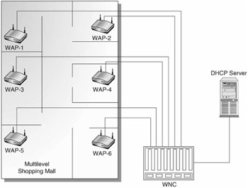
A more sophisticated approach to enabling WiFi networks introduces the notion of a wireless network controller (WNC), which manages a group of WAPs (see Figure 5.3). In this type of network, the WNC is able to control WAP handovers to improve the overall performance of the network.

Figure 5.3: A wireless network controller network.
Location determination techniques specific to WiFi networks are addressed in Chapter 7.
EAN: 2147483647
Pages: 129