Class Diagrams for Lathe3D
Chapter 17. Using a Lathe to Make ShapesI've run up against the lack of useful shapes in Java 3D many times: there's only so much that can be done with the Box, Cone, Cylinder, and Sphere classes. One way of getting past this limitation is to use Java 3D's GeometryArray (or one of its subclasses) to specify a geometry in terms of separate arrays of positional coordinates, colors, normals, and texture coordinates. This is pretty daunting, and I like to avoid it if possible. An alternative to this low-level shape building is to follow the approach outlined in Chapter 16: create the shape in a 3D modeling package and load it into Java 3D. The drawback is that you need to learn the modeling software. Most of these packages have so many bells and whistles that it's hard to get what you need done. This chapter describes a compromise between the complexity of Java 3D GeometryArrays and the loading of ready-made models. The edge of a shape is defined in terms of straight lines and simple curves. This edge (or lathe curve) is rotated around the y-axis to create a 3D volume, called a lathe shape. This approach, often called surface or sweep revolution, is packaged up in a LatheShape3D class. Color or texture information can be added easily. A lathe shape is pink by default, but this can be changed to a different color or texture. In both cases, the shape will reflect light (i.e., a shape's faces always have normals). A color is defined using two Color3f objects: one for ambient illumination (typically a dark hue) and the other for diffuse lighting.
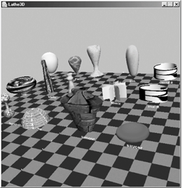
A texture is wrapped around the shape starting from the middle of the shape's back (the side facing away from the camera position), continuing counterclockwise around the front, and ending back where it started. The texture is stretched in the y-direction, ensuring it covers the shape vertically. Figure 17-1 shows a selection of LatheShape3D objects. Figure 17-1. LatheShape3D objects
This chapter illustrates the following features:
|
EAN: 2147483647
Pages: 340
