Configuring a PPTP-Based Site-to-Site VPN Connection
To create a PPTP VPN connection, perform the following tasks:
-
Configure VPN support on the answering router.
-
Configure the demand-dial interface on the answering router.
-
Configure VPN support on the calling router.
-
Configure the demand-dial interface on the calling router.
-
Initiate the VPN connection.
-
Test the VPN connection.
Configuring VPN on the Answering Router
Perform the following steps to run the Routing And Remote Access Server Setup Wizard on ROUTER1.
-
In the Routing And Remote Access snap-in, right-click ROUTER1 in the console tree, and then click Configure And Enable Routing And Remote Access.
-
To complete the Routing And Remote Access Server Setup Wizard, click Next, and then provide the information described in the following steps.
-
On the Configuration page, select Remote Access (Dial-up Or VPN).
-
Click Next. On the Remote Access page, select VPN.
-
Click Next. On the VPN Connection page, select the interface that is attached to the Internet (the one with the IP address of 10.1.0.2), and verify that the Enable Security On The Selected Interface By Setting Up Static Packet Filters check box is selected.
-
Click Next. On the Network Selection page, select the interface that is attached to the Seattle subnet (the one with the IP address of 172.16.4.1).
-
Click Next. On the IP Address Assignment page, select From A Specified Range Of Addresses.
-
Click Next. On the Address Range Assignment page, click New.
-
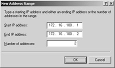
On the New Address Range page, do the following:
-
In the Start IP Address text box, type: 172.16.100.1.
-
In the End IP Address text box, type: 172.16.100.2.
-
In the Number Of Addresses text box, do not change value of 2.
The resulting dialog box is shown in the following figure.
-
-
Click OK. On the Address Range Assignment page, click Next.
-
On the Managing Multiple Remote Access Servers page, select No, Use Routing And Remote Access To Authenticate Connection Requests.
-
Click Next. On the Completing The Routing And Remote Access Server Setup Wizard page, click Finish.
Configuring the Demand-Dial Interface on the Answering Router
Perform the following steps to run the Demand-Dial Interface Wizard on ROUTER1.
-
In the Routing And Remote Access snap-in, expand ROUTER1 and right- click Network Interfaces.
-
To start the Demand-Dial Interface Wizard, click New Demand-Dial Interface. On the Welcome To The Demand Dial Interface Wizard page, click Next.
-
On the Interface Name page, type VPN_NewYork.
-
Click Next. On the Connection Type page, select Connect Using Virtual Private Networking (VPN).
-
Click Next. On the VPN Type page, select Point To Point Tunneling Protocol (PPTP).
-
Click Next. On the Destination Address page, type 10.2.0.2 in the Host Name Or IP Address text box.
-
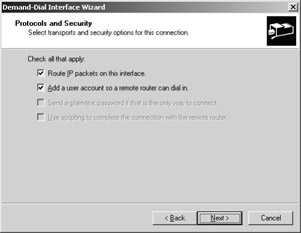
Click Next. On the Protocols And Security page, do the following:
-
Select Route IP Packets On This Interface.
-
Select Add A User Account So A Remote Router Can Dial In, as shown in the following figure.
-
-
Click Next. On the Static Routes For Remote Networks page, click Add.
-
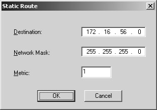
In the Static Route dialog box, do the following:
-
In the Destination text box, type: 172.16.56.0.
-
In the Network Mask text box, type: 255.255.255.0.
-
In the Metric text box, accept the displayed value 1, as shown in the following figure.
-
-
Click OK. On the Static Routes For Remote Networks page, click Next.
-
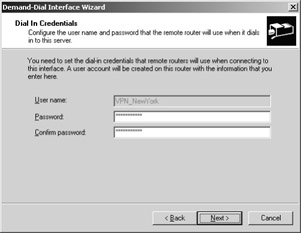
On the Dial In Credentials page, type a password for the VPN_NewYork user account and confirm the password. The User Name text box is prepopulated with the value, VPN_NewYork. This is shown in the following figure.
-
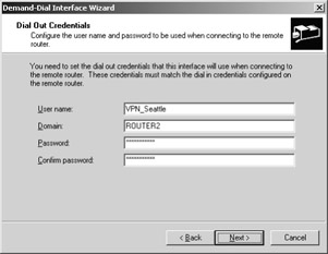
Click Next. On the Dial Out Credentials page, do the following:
-
In the User Name text box, type: VPN_Seattle.
-
In the Domain text box, type: ROUTER2.
-
In the Password text box, type a password for the VPN_Seattle user account.
-
In the Confirm Password text box, retype the password for the VPN_Seattle user account.
-
-
Click Next. On the last Demand-Dial Interface Wizard page, click Finish.
Configuring VPN on the Calling Router
Perform the following steps to run the Routing And Remote Access Server Setup Wizard on ROUTER2:
-
In the Routing And Remote Access snap-in, right-click ROUTER2 in the console tree, and then click Configure And Enable Routing And Remote Access.
-
To complete the Routing And Remote Access Server Setup Wizard, click Next, and then provide the information described in the following steps.
-
On the Configuration page, select Remote Access (Dial-up Or VPN) and then click Next.
-
On the Remote Access page, select VPN and then click Next.
-
On the VPN Connection page, select the interface that is attached to the Internet (the one with the IP address of 10.2.0.2), and verify that the Enable Security On The Selected Interface By Setting Up Static Packet Filters check box is selected, and click Next.
-
On the Network Selection page, select the interface that is attached to the New York subnet (the one with the IP address of 172.16.56.1) and click Next.
-
On the IP Address Assignment page, select From A Specified Range Of Addresses and click Next. On the Address Range Assignment page, click New and do the following:
-
In the Start IP address text box, type: 172.56.200.1.
-
In the End IP address text box, type: 172.56.200.2.
-
In the Number Of Addresses text box, do not change value of 2, and then click OK.
-
-
On the Address Range Assignment page, click Next.
-
On the Managing Multiple Remote Access Servers page, select No, Use Routing And Remote Access To Authenticate Connection Requests. Click Next.
-
On the Completing The Routing And Remote Access Server Setup Wizard page, click Finish.
Configuring the Demand-Dial Interface on the Calling Router
Perform the following steps to run the Demand-Dial Interface Wizard on ROUTER2.
-
In the Routing And Remote Access snap-in, expand ROUTER2 and right- click Network Interfaces.
-
To start the Demand-Dial Interface Wizard, click New Demand-Dial Interface. On the Welcome To The Demand Dial Interface Wizard page, click Next.
-
On the Interface Name page, type VPN_Seattle. The interface name must match the user account name used in the user credentials of the calling router. Click Next.
-
On the Connection Type page, select Connect Using Virtual Private Networking (VPN). Click Next.
-
On the VPN Type page, select Point To Point Tunneling Protocol (PPTP). Click Next.
-
On the Destination Address page, type 10.1.0.2 and then click Next.
-
On the Protocols And Security page, do the following:
-
Select Route IP Packets On This Interface.
-
Select Add A User Account So A Remote Router Can Dial In and then click Next.
-
-
On the Static Routes For Remote Networks page, click Add.
-
On the Static Route page, do the following:
-
In the Destination text box, type: 172.16.4.0.
-
In the Network Mask text box, type: 255.255.255.0.
-
In the Metric text box, accept the displayed value of 1, and then click OK.
-
-
On the Static Routes For Remote Networks page, click Next.
-
On the Dial In Credentials page, type the password for the VPN_Seattle user account, confirm the password, and click Next.
-
On the Dial Out Credentials page, type the following:
-
In the User Name text box, type: VPN_NewYork.
-
In the Domain text box: type ROUTER1, type the password for the VPN_NewYork user account created on ROUTER1, confirm the password, and click Next.
-
-
On the Completing The Demand-Dial Interface Wizard page, click Finish.
Initiating the VPN Connection
After completing all configuration tasks, initiate the VPN connection by performing the following steps:
-
On ROUTER2, in the console tree in the Routing And Remote Access snap- in, click Network Interfaces.
-
In the details pane, right-click the VPN_Seattle interface and then click Connect.
-
Confirm that the connection state of the VPN_Seattle demand-dial interface has been set to Connected.
Testing the VPN Connection
Perform the following tests to confirm that the VPN connection is working correctly:
-
On CLIENT2, ping CLIENT1 at its IP address of 172.16.4.3 to test whether the Seattle subnet is now reachable.
-
To confirm that the packets crossed the VPN connection on CLIENT2, type tracert 172.16.4.3 at a command prompt.
Results that are similar to the following indicate that the connection is working:
Tracing route to 172.16.4.3 over a maximum of 30 hops: 1 <1 ms <1 ms <1 ms [172.16.56.1] 2 1 ms <1 ms <1 ms [172.56.200.2] 3 1 ms 1 ms 1 ms [172.16.4.3] Trace complete.
In the Tracert display:
-
172.16.56.1 is the IP address of the ROUTER2 interface that connects to the New York intranet.
-
172.56.200.2 is the IP address that ROUTER2 assigned to ROUTER1 for the VPN connection. The presence of this IP address in the Tracert output indicates that packets are moving across the site-to-site VPN connection.
-
172.16.4.3 is the IP address of CLIENT1.
EAN: 2147483647
Pages: 128