Walkthrough: SDM Sample
Now that you have a conceptual understating of SDM, you can explore a more practical example. In the following sample, we will create the following setup:
| Note | Many thanks to Thomas Delrue, Software Development Engineer on the Team Architect product SKU team at Microsoft for providing the following SDM example. |
On the Application Designer layer (AD layer), we'll have a WindowsMobile Application with two accessibility-related settings. This application contains two (IRda) endpoints: one server endpoint and one client endpoint. These endpoints will be able to communicate with each other, and they both contain a setting specifying the size of the buffer on which they operate. We'll also allow the application to be a client of a web service, so we'll make sure the application can also contain a WebServiceClientEndpoint.
On the LDD side of things, we'll create a MobileDevice. This will represent any kind of device that is part of the WindowsMobile family (such as a SmartPhone, PDA, or related device). This server system will host the WindowsMobileApplication. The system will also contain both a server endpoint and client endpoint for communication over IrDA. In order to host the WebServiceClientEndpoint on the AD side, we'll allow a HTTPClientEndpoint to be placed on this logical server.
As this is a MobileDevice, we'll also specify that this system must contain at least one Common Language Runtime (which is the .NET 2.0 runtime).
In order to define a System Definition Model (SDM), we have to create a new XML file that will contain our model. This will be the SDM file (as opposed to the SDM document), which is the result of compiling the SDM file:
<?xml version="1.0" encoding="utf-8"?> <SystemDefinitionModel Name="Microsoft.SDM.Samples.Mobile" Version="0.1.0.0" DocumentLanguage="en" Culture="en-US" xmlns="http://schemas.microsoft.com/SystemDefinitionModel/2005/1"> </SystemDefinitionModel>
Note a couple of interesting things in this <SystemDefinitionModel/> tag. First of all, there is the name-space that we use for this XML file, xmlns=http://www.schemas.microsoft.com/systemDefinitionModel/2005/1. This indicates that we are using the SDM Schema and that it will be validated by the compiler when we compile the SDM file.
Secondly, there is the Document Identity Information. This information is contained in the attributes Name (which states the name of the document after compilation), Version (which indicates the version), and Culture. Just as with .NET assemblies, these values make up the identity of the document.
When the SDM file is compiled to an SDM document, the compiler computes a CompilationHash and adds this to the Document Identity Information. This CompilationHash is basically nothing more than a hash of the contents of the file. Upon validation of the SDM document, the content of the file is hashed and compared to the value in this attribute. This enables the compiler to detect whether or not somebody has modified the compiled SDM document. You can consider this hash value to perform the same task that the PublicKeyToken value performs in .NET assemblies. After adding this hash information, the document identity information is complete (and is then made up of Name, Version, Culture, and CompilationHash).
There is also a DocumentLanguage attribute, which specifies the language of the information contained in the document.
SystemDefinitions
To define the systems in our System Definition Model, we add following code to the SDM file:
<SystemDefinition Name="WindowsMobileApplication" Layer="Application" Abstract="true"> </SystemDefinition>
This defines our application system named WindowsMobileApplication. When defining this system, we immediately specify the layer on which it will live; in this case, it is the application layer (which is the SDM way of pointing to the AD). We are also creating "descriptions" of the system, so we have to specify that this is not an instance of WindowsMobileApplication, but a definition of that type. This is what the Abstract="true" does. It informs the compiler that this is an abstract type (as opposed to a concrete type, which is the instance of the abstract type on the Distributed System Designers).
Likewise, we create a SystemDefinition for the MobileDevice that will live on the LDD:
<SystemDefinition Name="MobileDevice" Layer="ApplicationHost" Abstract="true"> </SystemDefinition>
The only difference with the system for the AD is the value for the Layer attribute. In this case, this system lives on the LDD, so in order to specify this in SDM, we use the value ApplicationHost for the Layer attribute.
In order for the systems defined to show up in the deployment report, we have to add a DesignData section within the <SystemDefinition> of the application:
<DesignData> <Report Type="Application" xmlns="http://schemas.microsoft.com/ SystemDefinitionModel/2005/1/DesignData/DeploymentReport" /> </DesignData>
This ensures that the application will show up in the deployment report. For the logical server, we need to add this section inside of it:
<DesignData> <Report Type="LogicalServer" xmlns="http://schemas.microsoft.com/ SystemDefinitionModel/2005/1/DesignData/DeploymentReport" /> </DesignData>
If this information is not added, the application and logical server and the information they contain will not show up in the deployment report.
You can also add additional DesignData information to the SystemDefinition for aesthetic purposes:
<DesignData> <VisualStudio xmlns="http://schemas.microsoft.com/ SystemDefinitionModel/2005/1/DesignData/VisualStudio"> <ModelElement> <Property Name="PrimaryRelationshipName" Value="HostingDefinition" /> <Property Name="PrimaryRelationshipRole" Value="Host" /> <Property Name="ThemeColor" Value="61, 107, 206" /> <Property Name="ImageFileName" Value="OfficeApplication.emf" /> <Property Name="ErrorImageFileName" Value="OfficeApplicationError.emf" /> </ModelElement> </VisualStudio> </DesignData>
Both PrimaryRelationshipName and PrimaryRelationshipRole are properties used by the Settings and Constraints Editor. The value for PrimaryRelationshipRole for an application system is Guest, whereas for a server system it is Host.
ThemeColor provides a means to give color to the shape that will appear on the Distributed Systems Designers in the HSL (Hue, Saturation, Luminescence) format.
Both ImageFileName and ErrorImageFileName point to files that will be used as the icon of the shapes (normal and error view) on the Distributed Systems Designer. The normal icons of the Application and Application Host results are shown in Figure 7-11. Note that this is not the value for the icon used for the shape in the toolbox.
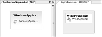
Figure 7-11
Settings
As described previously, we want some settings in the system, which will live on the application layer. We can specify this by adding <SettingDeclaration /> elements between the <SystemDefinition /> tags of the system that will contain these settings. Add the following SettingDeclarations to the WindowsMobileApplication system:
<SettingDeclaration Name="SupportsHighContrast" Definition="System:Boolean" CanBeNull="false" /> <SettingDeclaration Name="SupportsScreenReader" Definition="System:Boolean" CanBeNull="false" />
Obviously, the Name attribute specifies the name of the setting. CanBeNull specifies whether or not this setting is nullable (meaning it does not contain a value). If a setting is declared as CanBeNull="true", a checkbox will appear in the Settings and Constraints Editor that allows users to nullify the value for the setting (in other words, it removes the value for the setting).
In order for both the compiler and the Distributed System Designers to understand what kind of information you can store in the setting, you also have to provide a definition — this will be the datatype of the setting.
In this case, both settings are of type Boolean. However, the Boolean type is not defined in this SDM file; it is defined in another SDM document, so you will have to import this other SDM document and point the definition of the settings the right way. The SDM document containing the definition for Boolean is the System document. Add the following code to the top of your SDM file:
<Import Alias="System" Name="System" />
This Import statement will import an SDM document that has the document name System; this is specified by the Name attribute. If you want, you can specify additional elements making up the document identity information (such as Culture, Version, or CompilationHash), thus making more specifications about which system SDM document is to be imported.
You also provide an alias for the document. This alias will be used every time you reference something defined in this imported document.
This statement makes all definitions in the System document available in the SDM file you are currently editing. However, in order to use any definition in this document, you need to prepend the definition with the alias and a colon. This explains the System:Boolean value for the Definition attributes of the SettingDeclarations you just created.
You want these settings to have a default value too, so add the following SDM code to the WindowsMobileApplication SystemDefinition:
<SettingValue Path="SupportsHighContrast">false</SettingValue> <SettingValue Path="SupportsScreenReader">false</SettingValue>
These elements will set the default value for both the SupportsHighContrast and Supports ScreenReader settings to be false, as shown in Figure 7-12. Note that you use the Path attribute to target the setting for which you wish to set a default value. (Note : In this stage of the sample, we are defining the definition of the WindowsMobileApplication prototype and illustrating what it will look like with an existing WindowsApplication prototype. Later, you will see how these settings come together and describe the WindowsMobileApplication on the design surface.)

Figure 7-12
Endpoints
You will need to define four new endpoints: a server endpoint on both the AD and LDD layer and a client endpoint on both the AD and LDD layer.
Application layer
Add this information to create a ClientEndpoint:
<EndpointDefinition Name="ApplicationIrDAClientEndpoint" Layer="Application" Abstract="true"> <DesignData> <VisualStudio xmlns="http://schemas.microsoft.com/ SystemDefinitionModel/2005/1/DesignData/VisualStudio"> <ModelElement> <Property Name="PrimaryRelationshipName" Value="HostingDefinition" /> <Property Name="PrimaryRelationshipRole" Value="Guest" /> <Property Name="Direction" Value="Client" /> <Property Name="Geometry" Value="General" /> </ModelElement> </VisualStudio> </DesignData> </EndpointDefinition>
This defines an endpoint named ApplicationIrDAClientEndpoint that will live on the Application (AD) layer.
Note how this EndpointDefinition also contains the DesignData. In this case, you add some DesignData properties to the ModelElement representing the definition on the Distributed System Designers.
PrimaryRelationshipName and PrimaryRelationshipRole contain information for the Settings and Constraints Editor that enables it to determine what kind of constraints are to be displayed. As we are dealing with an endpoint on the AD layer, the values here respectively are HostingDefinition (the AD endpoint will be hosted on an LDD endpoint) and Guest (the AD endpoint is the Guest in that HostingDefinition).
The Direction property tells your designer the direction of the communication. Note that SDM does not contain this concept of direction (apart from Server vs. Client in CommunicationDefinitions or Host vs. Guest in HostingDefinitions), but our designers do. This property determines what end of the connection on the designer will contain the arrow. As this is a client endpoint, it gets the value Client.
The AD designer has a couple of geometries that can be used. This geometry determines the shape of the endpoint. The value General in the Geometry property uses the default squared display of the end-point, as shown in Figure 7-13.
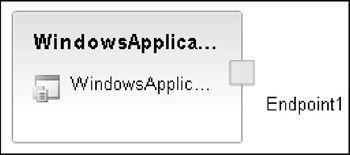
Figure 7-13
Likewise, you can create a server endpoint for the AD layer:
<EndpointDefinition Name="ApplicationIrDAServerEndpoint" Layer="Application" Abstract="true"> <DesignData> <VisualStudio xmlns="http://schemas.microsoft.com/ SystemDefinitionModel/2005/1/DesignData/VisualStudio"> <ModelElement> <Property Name="PrimaryRelationshipName" Value="HostingDefinition" /> <Property Name="PrimaryRelationshipRole" Value="Guest" /> <Property Name="Geometry" Value="General" /> <Property Name="ThemeColor" Value="145, 137, 213" /> </ModelElement> </VisualStudio> </DesignData> </EndpointDefinition>
Note the subtle differences between a server endpoint and a client endpoint: the server endpoint does not contain the Direction property, but in exchange it does contain a ThemeColor property.
This ThemeColor property takes a color specification in the HSL (Hue, Saturation, Luminescence) format, as shown in Figure 7-14. (This difference may appear slight in this publication.)
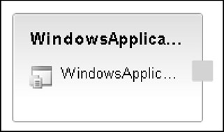
Figure 7-14
Settings
Both this client and server endpoints will contain a setting called BufferSize, which will be of definition Int (defined in the System document) and not nullable. On the server endpoint, this will look like the following:
<SettingDeclaration Name' "BufferSize" Definition="System:Int" CanBeNull="false" /> <SettingValue Path="BufferSize">1024</SettingValue>
As you already imported the System document, you can reference anything within it without any need for an Import statement, as shown in Figure 7-15.

Figure 7-15
On the client endpoint, you will add a more complex setting because it will be used later in a flow and a constraint:
<SettingDeclaration Name="BufferSize" Definition="System:Int" CanBeNull="false" DefaultRead="Default" DefaultWrite="Assigned"> <Facet Name="Default" /> <Facet Name="Assigned" /> <Facet Name="Resultant" /> </SettingDeclaration>
The setting defined in the client endpoint contains facets. The setting has three facets (Default, Assigned, and Resultant), which will enable you to put multiple values in this setting.
Next to the usual SettingDeclaration attributes are two extra ones: DefaultRead and DefaultWrite; these respectively point toward the facet used when grabbing the value from the setting, without specifying the facet name to read from, and the facet used when storing a value in the setting, without specifying the facet in which to store it.
In the Settings and Constraints Editor, these facets will not show up; the setting appears as a unity with no default value (as you did not assign one to it), as shown in Figure 7-16.

Figure 7-16
Application Host Layer
We have previously defined the endpoints for the ApplicationLayer; likewise, we will define the end-points that will live on the ApplicationHost layer:
<EndpointDefinition Name="IrDAServerEndpoint" Layer="HostLayer" Abstract="true"> <DesignData> <VisualStudio xmlns="http://schemas.microsoft.com/SystemDefinitionModel/ 2005/1/DesignData/VisualStudio"> <ModelElement> <Property Name="PrimaryRelationshipName" Value="HostingDefinition" /> <Property Name="PrimaryRelationshipRole" Value="Host" /> <Property Name="ThemeColor" Value="145, 137, 213" /> <Property Name="Geometry" Value="General" /> </ModelElement> </VisualStudio> </DesignData> <SettingDeclaration Name="MaxAllowedBufferSize" Definition="System:Int" CanBeNull="false" /> <SettingValue Path="MaxAllowedBufferSize">2048</SettingValue> </EndpointDefinition> <EndpointDefinition Name="IrDAClientEndpoint" Layer="HostLayer" Abstract="true"> <DesignData> <VisualStudio xmlns="http://schemas.microsoft.com/SystemDefinitionModel/ 2005/1/DesignData/VisualStudio"> <ModelElement> <Property Name="PrimaryRelationshipName" Value="HostingDefinition" /> <Property Name="PrimaryRelationshipRole" Value="Host" /> <Property Name="Direction" Value="Client" /> <Property Name="ThemeColor" Value="145, 137, 213" /> <Property Name="Geometry" Value="General" /> </ModelElement> </VisualStudio> </DesignData> <SettingDeclaration Name="MaxAllowedBufferSize" Definition="System:Int" CanBeNull="false" /> <SettingValue Path="MaxAllowedBufferSize">2048</SettingValue> </EndpointDefinition>
On the LDD layer, we now have defined two endpoints. There is a server endpoint named IrDAServerEndpoint, which will live on the ApplicationHost layer. This endpoint contains a SettingDeclaration MaxAllowedBufferSize of type Int, which will indicate the maximum allowed value for the value of BufferSize in an ApplicationIrDAServerEndpoint that is hosted on IrDAServerEndpoint. This setting also has as a default value of 2048.
We also defined a client endpoint named IrDAClientEndpoint, which has the same SettingDeclaration with the same default value.
Communication and delegation
We have defined two endpoints on each side, but without the possibility of communication between them, there is not much use for them there, so we'll add that possibility to the SDM file:
<CommunicationDefinition Name="AppIrDACommunication" ServerDefinition="ApplicationIrDAServerEndpoint" ClientDefinition="ApplicationIrDAClientEndpoint" /> <CommunicationDefinition Name="IrDACommunication" ServerDefinition="IrDAServerEndpoint" ClientDefinition="IrDAClientEndpoint" />
This ensures that on each layer, the client and server endpoint can communicate with each other, as shown in Figure 7-17.
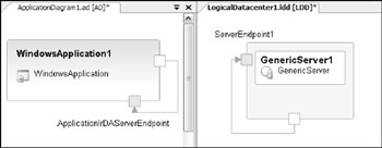
Figure 7-17
When application systems are contained in different systems (SDs in Distributed System Designers) and they need to communicate with each other, this communication needs to occur through the boundary of that system. To allow this, we need to delegate the powers of the server endpoint to the boundaries of the system in which it is contained, as shown in Figure 7-18. Likewise, for the client endpoint, this delegation is also needed:
<DelegationDefinition Name="AppIrDAClientEndpointDelegation" DelegateDefinition="ApplicationIrDAClientEndpoint" ProxyDefinition="ApplicationIrDAClientEndpoint" /> <DelegationDefinition Name="AppIrDAServerEndpointDelegation" DelegateDefinition="ApplicationIrDAServerEndpoint" ProxyDefinition="ApplicationIrDAServerEndpoint" />
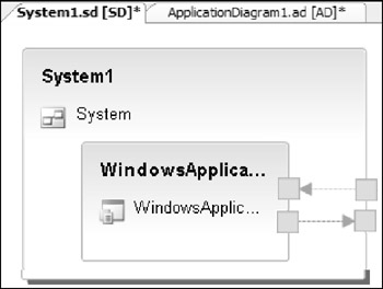
Figure 7-18
Containment
We have now defined two systems, four endpoints, and the communication definitions between them. However, this does not yet allow them to take part in the Distributed Systems Designers experience. You have to explicitly enable these systems and components to be contained in the systems that are represented by the Distributed System Designers. This is where a ContainmentDefinition comes in. SystemDefinitions that will live on the application layer need a ContainmentDefinition with a system called DistributedApplication, which is defined in the Microsoft.DistributedApplication SDM document. Therefore, you need an additional Import statement that imports this SDM document, and we can define the ContainmentDefinition:
<Import Alias="DA" Name="Microsoft.DistributedApplication" />
After adding this to the Imports section, you can continue with the ContainmentDefinition for the Application System (see Figure 7-19):
<ContainmentDefinition Name="DAcontainsWMA" ParentDefinition="DA:DistributedApplication" MemberDefinition="WindowsMobileApplication" />
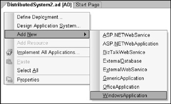
Figure 7-19
Similarly, you need to enable the ApplicationHost System to be contained in the datacenter. For this, you need a ContainmentDefinition between your ApplicationHost system on one side and the HostLayer (which is the system representing the LDD and defined in the Microsoft.Datacenter SDM document) on the other side (as shown in Figure 7-20):
<Import Alias="DC" Name="Microsoft.Datacenter" /> <ContainmentDefinition Name="DCcontainsWMD" ParentDefinition="DC:HostLayer" MemberDefinition="WindowsMobileDevice" /> <ContainmentDefinition Name="ZoneContainsWMD" ParentDefinition="DC:HostZone" MemberDefinition="WindowsMobileDevice" />
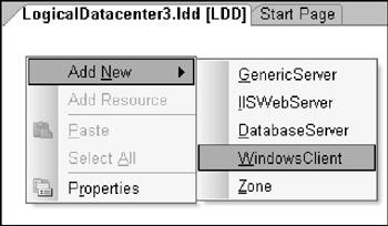
Figure 7-20
That last ContainmentDefinition enables the WindowsMobileDevice to be placed within a Zone on the LDD, as shown in Figure 7-21.
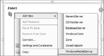
Figure 7-21
You also have to enable your endpoints to be placed — or contained, if you will — on the appropriate systems. This enables the endpoints on the application layer to be contained on the WindowsMobileApplication (as shown in Figure 7-22):
<ContainmentDefinition Name="WMAcontainsIRClientEndpoint" ParentDefinition="WindowsMobileApplication" MemberDefinition="ApplicationIrDAClientEndpoint" /> <ContainmentDefinition Name="WMAcontainsIRServerEndpoint" ParentDefinition="WindowsMobileApplication" MemberDefinition="ApplicationIrDAServerEndpoint" />
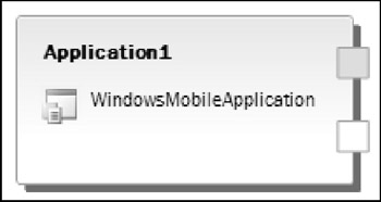
Figure 7-22
As we have allowed delegation from an ApplicationIrDAClientEndpoint to an endpoint of the same type and an ApplicationIrDAServerEndpoint to an endpoint of the same type, we also have to allow these endpoints to be contained within a DistributedApplication (as shown in Figure 7-23):
<ContainmentDefinition Name="DAcontainsIRServerEndpoint" ParentDefinition="DA:DistributedApplication" MemberDefinition="ApplicationIrDAServerEndpoint" /> <ContainmentDefinition Name="DAcontainsIRClientEndpoint" ParentDefinition="DA:DistributedApplication" MemberDefinition="ApplicationIrDAClientEndpoint" />
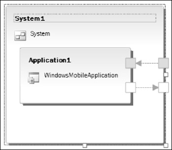
Figure 7-23
The following code enables the endpoints on the ApplicationHost layer to be contained on the WindowsMobileDevice system (as shown in Figure 7-24):
<ContainmentDefinition Name="WMDcontainsIrDAServerEndpoint" ParentDefinition="WindowsMobileDevice" MemberDefinition="IrDAServerEndpoint" /> <ContainmentDefinition Name="WMDcontainsIrDAClientEndpoint" ParentDefinition="WindowsMobileDevice" MemberDefinition="IrDAClientEndpoint" />
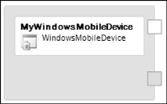
Figure 7-24
In addition, we will also allow the following three things:
-
The Application system can contain a WebServiceClientEndpoint (defined in the Microsoft.Web SDM document) to consume Web services.
-
The ApplicationHost system will contain an HttpClient endpoint so that it can communicate with IIS Servers — for instance, to query a Web service. (This endpoint is also defined in the Microsoft.Web SDM document.)
-
We can ensure that the WindowsMobileDevice will be .NET-ready by enabling it to contain a CommonLanguageRunTime (defined in the Microsoft.CommonLanguageRuntime SDM document).
To accomplish this, we need to add these two SDM documents to the Imports list:
<Import Alias="CLR" Name="Microsoft.CommonLanguageRuntime" /> <Import Alias="Web" Name="Microsoft.Web" />
Now you can define the ContainmentDefinition between these definitions (as shown in Figures 7-25, 7-26, and 7-27):
<ContainmentDefinition Name="WMAcontainsWebServiceClient" ParentDefinition="WindowsMobileApplication" MemberDefinition="Web:WebServiceClient" />
<ContainmentDefinition Name="WMDcontainsHTTPClient" ParentDefinition="WindowsMobileDevice" MemberDefinition="Web:HttpClient" />
<ContainmentDefinition Name="WMDcontainsCLR" ParentDefinition="WindowsMobileDevice" MemberDefinition="CLR:CommonLanguageRuntime" />

Figure 7-25
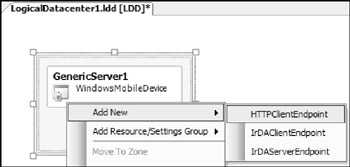
Figure 7-26
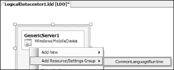
Figure 7-27
Hosting
As you are defining systems and endpoints on different layers, you need to provide the information that describes what types of hosting are allowed. After all, you deploy the systems and endpoints on the AD to the systems and endpoints on the LDD using the Deployment Designer (DD), so for this you need to define HostingDefinitions. These HostingDefinitions enable the application layer system to be hosted on the ApplicationHost layer system. This box-within-a-box hosting relationship using the DD is shown in Figure 7-28.
<HostingDefinition Name="WMDhostsWMA" HostDefinition="WindowsMobileDevice" GuestDefinition="WindowsMobileApplication" />
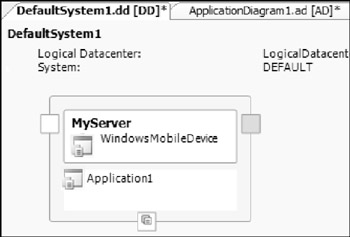
Figure 7-28
Likewise, you need to host your endpoints on their counterparts on the other layer (as shown in Figure 7-29):
<HostingDefinition Name="IrDAServerEndpointHostsApplicationIrDAServerEndpoint" HostDefinition="IrDAServerEndpoint" GuestDefinition="ApplicationIrDAServerEndpoint" /> <HostingDefinition Name="IrDAClientEndpointHostsApplicationIrDAClientEndpoint" HostDefinition="IrDAClientEndpoint" GuestDefinition="ApplicationIrDAClientEndpoint" />
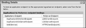
Figure 7-29
Note that you do not have to provide hosting information for the WebServiceClientEndpoint (which will be hosted onto an HttpClient endpoint). This information is already defined in the Microsoft.Web SDM document.
Flows
Flows enable values from one layer or object to flow to another. We will use this mechanism to flow a default value through the HostingDefinition that specifies that an IrDAClientEndpoint can host an ApplicationIrDAClientEndpoint. The flow will copy the value for MaxAllowedBufferSize of the IrDAClientEndpoint into the setting BufferSize on the ApplicationIrDAClientEndpoint if this endpoint did not provide a value itself. There is an InheritanceFlow defined in the System.Flows SDM document that will assist you with that. First you have to import that SDM document:
<Import Alias="Flow" Name="System.Flow" />
You now can access the InheritanceFlow defined in this SDM document.
This will flow the values from one layer (LDD layer) to another layer (AD/SD Layer), and will thus operate on a HostingDefinition. To be more precise, it will act on the HostingDefinition between the ApplicationIrDAClientEndpoint and the IrDAClientEndpoint named IrDAClient EndpointHostsApplicationIrDAClientEndpoint. The following statements need to be added within the HostingDefinition:
<Flow Name="ApplicationClientEndpointUsesMaxAllowedBufferSize" Definition="Flow:InheritanceFlow"> <Input Name="Assigned" Path="Guest.BufferSize@Assigned" /> <Input Name="Default" Path="Host.MaxAllowedBufferSize" /> <Output Name="Resultant" Path="Guest.BufferSize@Resultant" Cast="true" /> </Flow>
This flow takes two inputs: Assigned and Default. It takes Assigned from the Guest in the HostingDefinition (which is the ApplicationIrDAClientValue) and Default from the Host in the HostingDefinition (which is the IrDAClientEndpoint). The result of the flow will be stored in the output, which is located on the Guest. In order to store the output in the correct format, you have to cast it to the type of the output (Cast="true").
This is where the facets come in handy. By default, the value for the Assigned facet is empty, or null, but as soon as you put a value in the setting (without specifying a facet), it is stored in the Assigned facet, as defined by the DefaultWrite attribute on the SettingDeclaration. Therefore, if no specific value was specified, Assigned is null.
The other side of the equation comes from the Host; you read the value for MaxAllowedBufferSize.
InheritanceFlow does the following: It checks whether Assigned is null, and if it is, then the result is Default; if it is not null, then the result is Assigned.
The result is then stored in the Resultant output, which in this case maps to facet Resultant (the DefaultRead facet) of setting BufferSize on the Guest of the HostingDefinition.
This flow has the following effect: If no explicit value is set for the BufferSize setting on the ApplicationIrDAClientEndpoint, then it will use the maximum value allowed it finds on the host in MaxAllowedBufferSize.
Constraints
We have previously defined the possibilities that are allowed. Now it is time to rule out some situations. For this, SDM provides constraints in multiple forms.
RelationshipConstraints
We will constrain the relationship WMDcontainsCLR, which indicates that a WindowsMobileDevice can contain a CommonLanguageRuntime. The constraint we will place on this relationship is that it must contain at least one CommonLanguageRuntime. In order to do this, we need to add the following statements in the WindowsMobileDevice definition:
<RelationshipConstraint Name="WMDMustContainAtLeastOneCLR" RelationshipDefinition="WMDcontainsCLR" TargetRole="Member" TargetObjectDefinition="CLR:CommonLanguageRuntime" MinOccurs="1" />
It is imperative that this is added within the <SystemDefinition> of the WindowsMobileDevice as we are changing its very definition; we are imposing a constraint on this definition, so it must be defined within it. If this would be defined outside of the SystemDefinition for the WindowsMobileDevice, it would have no effect whatsoever.
The different parts of this RelationshipConstraint are the name (or type, if you will) of the relationship we are constraining against (RelationshipDefinition), which player in that relationship we are targeting (TargetRole), and the definition of that player (TargetObjectDefinition).
Lastly, we also have MinOccurs, which indicates that at least one instance of this relationship must occur. However, there is no upper limit. If we wanted to impose an upper limit, we could also have added the MaxOccurs-attribute to the RelationshipConstraint. Leaving either MinOccurs or MaxOccurs out indicates that for the attribute(s) that is/are left out, there is no limit.
When this constraint fails, it will show up in the Error List, as shown in Figure 7-30.

Figure 7-30
Both EndpointDefinitions contain a setting BufferSize. In order to have everything in working order, we want to constrain the CommunicationDefinition between the application server endpoint and the application client endpoint in such a way that the application client endpoint always has a value for BufferSize that is equal to or larger than the value for BufferSize on the Server endpoint. Therefore, we have to modify the CommunicationDefinition between these endpoints (AppIrDACommunication). For this, we will use an existing ConstraintDefinition (SimpleComparison) defined in the System.Constraints SDM document. This requires the following Import statement:
<Import Alias="Constraints" Name="System.Constraints" />
This gives us access to all of the definitions in System.Constraints.
The constraint that we will create validates that the values on both ends of the CommunicationDefinition meet the requirements, so in effect we have to "walk" the CommunicationDefinition. To do this, add the following code within the CommunicationDefinition named AppIrDACommunication:
<ObjectConstraint Name="GetServer" PrimaryObjectDefinition="ApplicationIrDAServerEndpoint" PrimaryRole="Server"> <RelationshipConstraint Name="GetClient" RelationshipDefinition="AppIrDACommunication" TargetObjectDefinition="ApplicationIrDAClientEndpoint" TargetRole="Client"DelegationAware="true" RaiseError="true"> </RelationshipConstraint> </ObjectConstraint>
The ObjectConstraint GetServer is our point of insertion. It targets one of the players in the relationship we are constraining. It declares that the object we are targeting plays the Server role (PrimaryRole) and that this object is of type ApplicationIrDAServerEndpoint (PrimaryObjectDefinition). This ObjectConstraint will make all settings of this targeted ObjectDefinition available through GetServer.[SettingName].
From the object playing the Server role, we have to walk to the client so we can grab the values there also. We do this using a RelationshipConstraint named GetClient. It specifies the relationship we are walking (AppIrDACommunication) and where we are walking to — namely, the object playing the role of Client in that relationship, which is of type ApplicationIrDAClientEndpoint. Additionally, we specify that this RelationshipConstraint is delegation-aware, which means that if communication passes through delegated endpoints on subsystems, the compiler will determine which actual end-point on what Application system is talking to which other actual endpoint on another Application system.
The RaiseError attribute informs the compiler that the constraint we are building can raise effective constraint errors.
By defining this RelationshipConstraint, we can now access all SettingDeclarations on the client of relationship AppIrDACommunication by using GetClient.Client.[SettingName].
Constraint Validation
We have just provided the path that we will walk in order to grab the settings on both ends of the CommunicationDefinition between the ApplicationIrDAClientEndpoint and the Application IrDAServerEndpoint. We now have to add the actual constraint that will perform the comparison between the values on both sides. Within the path we have just provided (within the inner Relationship Constraint named GetClient) we will add the actual constraint that validates whether the Client Endpoint has a buffer that is at least the size of the buffer on the ServerEndpoint or bigger:
<Constraint Name="ValidateClientBufferCanHandleServerBuffer" Definition="Constraints:SimpleComparison"> <Input Name="ActualValue" Path="GetClient.Client.BufferSize@Resultant" /> <Input Name="DesiredValue" Path="GetServer.BufferSize" /> </Constraint>
This constraint (defined in System.Constraints as SimpleComparison) takes three inputs, and the ActualValue, the DesiredValue, and the Operator are applied to these values. As described earlier, we provided two inputs already: the ActualValue coming from the client in the CommunicationDefinition (GetClient.Client.BufferSize@Resultant, which is the value after the flow defined earlier has occurred) and the DesiredValue coming from the server in the CommunicationDefinition (GetServer.BufferSize).
The value for the operator will be a constant, so it will not come from one of the two players in the CommunicationDefinition. Instead, we will have it come from the CommunicationDefinition itself, where we will define it and give it a default value. Therefore, to the CommunicationDefinition AppIrDACommunication we will add the following SettingDeclaration:
<SettingDeclaration Name="Operator" Definition="System:String" CanBeNull="false" /> <SettingValue Path="Operator">>=</SettingValue>
This creates a setting Operator in the CommunicationDefinition with the default value >= (which indicates "greater than or equal to"). With this setting in place, we can use it inside the constraint by calling it directly (as it is directly available) through an Input in the constraint:
<Input Name="Operator" Path="Operator" />
This concludes this constraint; it reads the value from the Client Endpoint (GetClient.Client.BufferSize@Resultant), which is the result of the flow defined earlier, reads the value from the Server Endpoint (GetServer.MaxBufferSize) into DesiredValue, and computes that it must be larger than or equal to ActualValue as instructed by the value of Operator.
When this constraint it triggered and fails, it will show up in the ErrorList as shown in Figure 7-31.

Figure 7-31
We will do something similar with the HostingDefinition, which defines that an IrDAServerEndpoint can host an ApplicationIrDAServerEndpoint. In the HostingDefinition named IrDAServerEndpointHostsApplicationIrDAServerEndpoint, we will state that the value for BufferSize on the Application endpoint cannot exceed the value of MaxAllowedBufferSize on the ApplicationHost endpoint:
<SettingDeclaration Name="Operator" Definition="System:String" /> <SettingValue Path="Operator">>=</SettingValue> <Constraint Name="AppEndpointCannotExceedServerValue" Definition="Constraints:SimpleComparison"> <Input Name="DesiredValue" Path="Guest.BufferSize" /> <Input Name="ActualValue" Path="Host.MaxAllowedBufferSize" /> <Input Name="Operator" Path="Operator" /> </Constraint>
A failure of this constraint will show up in the ErrorList as shown in Figure 7-32.

Figure 7-32
Likewise in HostingDefinition IrDAClientEndpointHostsApplicationIrDAClientEndpoint, which defines that an IrDAClientEndpoint on the ApplicationHost layer can host an ApplicationIrDAClientEndpoint from the application layer. In this relationship, we already defined a flow, but we can define this constraint nicely next to the flow and have them co-exist:
<SettingDeclaration Name="Operator" Definition="System:String" /> <SettingValue Path="Operator">>=</SettingValue> <Flow Name="ApplicationClientEndpointUsesMaxAllowedBufferSize" Definition="Flow:InheritanceFlow"> <Input Name="Assigned" Path="Guest.BufferSize@Assigned" /> <Input Name="Default" Path="Host.MaxAllowedBufferSize" /> <Output Name="Resultant" Path="Guest.BufferSize@Resultant" Cast="true" /> </Flow> <Constraint Name="GuestCannotExceedMaxAllowedBufferSize" Definition="Constraints:SimpleComparison"> <Input Name="DesiredValue" Path="Guest.BufferSize@Resultant" /> <Input Name="ActualValue" Path="Host.MaxAllowedBufferSize" /> <Input Name="Operator" Path="Operator" /> </Constraint>
All we have to do is add the SettingDeclaration, the SettingValue, and the Constraint.
Creating your own constraints
In the SystemDefinition for the Application system (WindowsMobileApplication), we defined two settings: SupportsHighContrast and SupportsScreenReader. We want to define some logic validating that both values are set to true; otherwise, the application might not fully support the accessibility features available and we wish to fire off a warning to users when they validate the DD.
However, there is no constraint defined yet that takes two values and ensures that both are set to a specific value, so we will have to define this constraint ourselves. Because we are defining a constraint that will make a call back into compiled code, we need to "reference" that code (similar to when we import another SDM document). To reference compiled code, you declare a Manager:
<Manager Name="AccessibilityManager" AssemblyName="Microsoft.SDM.Samples.Mobile.AccessibilityManager" SourcePath="Microsoft.SDM.Samples.Mobile.AccessibilityManager.dll" />
This definition contains a Name, which will be used whenever you point to something within that code; an AssemblyName that follows the same format as any other full-fledged .NET AssemblyName (name, version, culture, and publicKeyToken), and a SourcePath, informing the compiler where (filename) this code can be located.
Now you can define your constraint:
<ConstraintDefinition Name="EnsureAccessibilitySupport" Manager="AccessibilityManager" ClrClassName="Microsoft.SDM.Samples.AccessibilityManager. CEnsureAccessibilitySupport"> <SettingDeclaration Name="SupportsHighContrast" Definition="System:Boolean" /> <SettingDeclaration Name="SupportsScreenReader" Definition="System:Boolean" /> </ConstraintDefinition>
As with any definition, this ConstraintDefinition needs a Name (EnsureAccessibilitySupport), which you will use later to indicate what type of constraint you want; a Manager, which points you toward the assembly containing the manager code; and a ClrClassName, which informs the compiler what class in the manager assembly should be used to execute this constraint.
Next to that, you provide SettingDeclarations, which provide a way for SDM values to be passed into the compiled code.
As you create the Manager and ConstraintDefinition, it is obvious that there is no assembly named Microsoft.SDM.Samples.Mobile.AccessibilityManager.dll…yet!
This is where the tools in the SDM SDK come into play for the first time.
SdmG
SdmG (SDM Manager Generator) is a tool delivered with the SDM SDK that is capable of generating a skeleton for your manager code based on SDM that you provide to the tool. By running your SDM file through SdmG, SdmG will generate (in this case) a partial class that contains the basic framework to implement the manager. Unfortunately, you need to provide not only the SDM file that contains the ConstraintDefinition for which to generate the manager, but also all SDM documents referenced by that SDM file and all the SDM documents referenced in those SDM documents, and so on.
This is how the call to SdmG will look:
$> SdmG Microsoft.SDM.Samples.Mobile.sdm /Classes+ /Constraints+ /S "C:\program files\microsoft visual studio 8\common7\ide\PrivateAssemblies" /R Microsoft.DistributedApplication.sdmDocument /R Microsoft.Datacenter.sdmDocument /R System.Constraints.sdmDocument /R Microsoft.CommonLanguageRuntime.sdmDocument /R System.Flow.sdmDocument /R Microsoft.Web.sdmDocument /R Microsoft.FileSystem.sdmDocument
Using the /Classes+ and /Constraints+ switches, you instruct SdmG to generate classes for the ConstraintDefinitions in the SDM file (Microsoft.SDM.Samples.Mobile.sdm) you provided. You also provide all referenced SDM documents using the /R switches and a search path whereby SdmG will look for these documents using /S.
The following command provides you with a complete view of all of SdmG's switches:
$> SdmG /?
The result of our original SdmG command will be a file named Microsoft.SDM.Samples.Mobile.cs as specified by the ClrClassName attribute of the ConstraintDefinition. If you open this file, the content will look like this:
// ---------------------------------------------------------------------------- // <auto-generated> // This code was generated by a tool. // Runtime Version:2.0.50426.0 // // Changes to this file may cause incorrect behavior and will be lost if // the code is regenerated. // </auto-generated> // ---------------------------------------------------------------------------- /// This file was generated using SdmG.exe, version=1.0.50000.0 namespace Microsoft.SDM.Samples.AccessibilityManager { using System; public partial class CEnsureAccessibilitySupport : Microsoft.SystemDefinitionModel.Manager.IConstraint { public bool SupportsHighContrast; public bool SupportsScreenReader; } } The first important thing to notice is that the class generated by the tool is a partial class. This enables you to add the logic in a different file and then compile both files into one class. If this were not a partial class and you re-generated your manager using SdmG, it would blow away the implementation code you have already added to the file. Therefore, it is good practice to use this C# 2.0 feature; leave the code generated by SdmG alone and perform the implementation in a separate file, which will then be compiled with the generated file into one assembly.
To implement the manager code, create a new .cs file (called Microsoft.SDM.Samples.Mobile.CEnsureAccessibilitySupport.cs) and place the following code in it:
//This file contains the 'second part' of the manager code class using System; using System.Collections.Generic; using Microsoft.SystemDefinitionModel.Manager; namespace Microsoft.SDM.Samples.AccessibilityManager { //IConstraint can be found in Microsoft.SystemDefinitionModel.Manager public partial class CEnsureAccessibilitySupport : IConstraint{ public ConstraintError[] Evaluate (){ List<string> lstViolators = new List<string> (); if (!SupportsHighContrast) lstViolators.Add ("SupportsHighContrast"); if (!SupportsScreenReader) lstViolators.Add ("SupportsScreenReader"); return ( SupportsHighContrast && SupportsScreenReader ? null : new ConstraintError[] { new ConstraintError ( 2005 /*errorID*/, "No good Accessibility Support!" /*Error Description*/, lstViolators.ToArray () /*Inputs causing the error*/) } ); } } } Here again you define a partial class CEnsureAccessibilitySupport, which will be merged with the CEnsureAccessibilitySupport in the Microsoft.SDM.Samples.Mobile.cs file by the compiler, which contains the implementation for the IConstraint interface — namely, the Evaluate() method.
This method will perform the actual logic required for the constraint. In this case, it creates a list of violating settings (which are the exact same names of the settings as defined in SDM) that will contain one entry for every setting that this constraint deems inappropriate.
If the value of SupportsHighContrast is not true, it will add the name of that setting (as defined in the ConstraintDefinition) to the list of violators. Similarly, it will add the name of the setting SupportsScreenReader to that same list if it is not set to true.
Lastly, it performs a check: If both values were indeed set to true it returns null, indicating that all is well. If any of these settings were not set to null, it returns an array of ConstraintErrors (defined in Microsoft.SystemDefinitionModel.Manager), which — in this case — contain just one ConstraintError.
The ConstraintError object takes three parameters: the ID of the error; a description of the error, which is the description that will appear in the ErrorList after validating the DD in Visual Studio; and an array of strings (System.String) of settings causing this ConstraintError. For each element in this array of strings of offending settings, Visual Studio will create a MenuItem under the GoTo menu item of the context menu that appears when you right-click on the error in the Visual Studio ErrorList that enables you to navigate to this offending setting.
Note that the names of the offending settings are the names of the SettingDeclarations in the ConstraintDefinition, not the name of the path filling in the values of this input.
After the implementation of this manager code, you need to compile both files into one assembly using the C# Compiler (csc.exe):
$> csc /out:Microsoft.SDM.Samples.Mobile.AccessibilityManager.dll /target:library /r:%SDMSDK%\Microsoft.Sdm.Manager.dll Microsoft.SDM.Samples.Mobile.cs Microsoft.SDM.Samples.Mobile.CEnsureAccessibilitySupport.cs
This compiles both files into an assembly named Microsoft.SDM.Samples.Mobile.AccessibilityManager (as specified by the SourcePath attribute of the Manager declaration). In order for the compiler to resolve all references, you provide the path to the Microsoft.Sdm.Manager.dll assembly as a referenced assembly (you will need to replace %SDMSDK% with the path to this file on your machine; or populate this environment variable with the appropriate value). You also specify that you want a library assembly as output (.dll) through the /target switch.
This results, as expected, in the assembly that you specified in the declaration AccessibilityManager.
Enforcing your constraint
Just as you created a <Constraint\> from a ConstraintDefinition predefined in System.Constraint, you can now create a <Constraint /> from the ConstraintDefinition you defined earlier in your SDM file.
This constraint restricts the SystemDefinition for the WindowsMobileApplication, so you need to place this constraint within that SystemDefinition:
<Constraint Name="EnsureApplicationSupportsAccessibility" Definition="EnsureAccessibilitySupport"> <Input Name="SupportsHighContrast" Path="SupportsHighContrast" /> <Input Name="SupportsScreenReader" Path="SupportsScreenReader" /> </Constraint>
You define this constraint and instruct it to use the definition named EnsureAccessibilitySupport, which requires two inputs: SupportsHighContrast and SupportsScreenReader. The value for these inputs can come from the SettingDeclarations that are directly available in this SystemDefinition (and are, coincidentally, named the same).
If your application fails this constraint, you will find an error message in your ErrorList like the one shown in Figure 7-33.

Figure 7-33
If only ScreenReader is set to false, the error will look like the one shown in Figure 7-34.

Figure 7-34
SdmC
Before you can use the SDM file you have been authoring in the Distributed Systems Designers (DSDs), you need to run it through the SDM Compiler (SdmC). By running your SDM file through SdmC, you are guaranteed that if the compiler does not report any errors, the resulting SDM document does not contain any semantic or syntactic errors. However, SdmC obviously does not point out errors in logic. You can get a full list of commands for SdmC by executing this command:
$> SdmC /?
To compile the SDM file you have been authoring, execute this command:
$> sdmc Microsoft.SDM.Samples.Mobile.sdm /S "C:\program files\microsoft visual studio 8\common7\ide\PrivateAssemblies" /R Microsoft.DistributedApplication.sdmDocument /R Microsoft.Datacenter.sdmDocument /R System.Constraints.sdmDocument /R Microsoft.CommonLanguageRuntime.sdmDocument /R System.Flow.sdmDocument /R Microsoft.Web.sdmDocument
Similarly to SdmG, you provide the file you wish to compile (Microsoft.SDM.Samples.Mobile.sdm); a search path in which SdmC will look for referenced files (/S); and the list of referenced files (/R).
The result of this statement will be a file named Microsoft.SDM.Samples.Mobile.sdmDocument that can be used by the DSDs (unless a different filename was specified using the /output switch).
ProtoGen
You have defined two SystemDefinitions and four EndpointDefinitions in the SDM file that you just compiled to an SDM document. In order to make those accessible to the DSDs and enable Visual Studio to ensure that these are represented in the toolbox so that they can be dragged onto the designer, you need to create prototypes. To do this, you can use another SDM SDK tool called ProtoGen. For a full list of options, execute this command:
$> ProtoGen /?
To generate the prototypes for the two systems, execute these two commands:
$> ProtoGen /Type System /Layer Application /Document Microsoft.SDM.Samples.Mobile /TypeName WindowsMobileApplication $> ProtoGen /Type System /Layer Host /Document Microsoft.SDM.Samples.Mobile /TypeName WindowsMobileDevice
In its purest form, ProtoGen takes four parameters: the type of SDM element on which you operate (/Type), which can be either System or Endpoint; the layer on which this SDM element lives (/Layer) or, in other words, in which toolbox it appears, the application layer (AD) or the host layer (LDD); the document identity information of the SDM document in which this system is defined (/Document); and the name of the SDM element for which to create a prototype (/TypeName).
The preceding command will result in two prototype files: WindowsMobileApplication.adPrototype, which is a prototype that will appear in the AD toolbox, and WindowsMobileDevice.lddPrototype, which will appear in the LDD toolbox. You can specify a different name for the prototype file by using the /output switch.
Likewise, you can create the prototypes for your four EndpointDefinitions:
$> ProtoGen /Type Endpoint /Layer Application /Document Microsoft.SDM.Samples.Mobile /TypeName ApplicationIrDAServerEndpoint $> ProtoGen /Type Endpoint /Layer Application /Document Microsoft.SDM.Samples.Mobile /TypeName ApplicationIrDAClientEndpoint $> ProtoGen /Type Endpoint /Layer Host /Document Microsoft.SDM.Samples.Mobile /TypeName IrDAServerEndpoint $> ProtoGen /Type Endpoint /Layer Host /Document Microsoft.SDM.Samples.Mobile /TypeName IrDAClientEndpoint
These commands will generate four files:
-
ApplicationIrDAServerEndpoint.adPrototype
-
ApplicationIrDAClientEndpoint.adPrototype
-
IrDAServerEndpoint.lddPrototype
-
IrDAClientEndpoint.lddPrototype
When you are done compiling and generating prototypes, you are almost ready to use your freshly compiled SDM document with prototypes in the DSDs.
The registry
Before you can use these prototypes you have to place them in a location Visual Studio knows about.
To instruct Visual Studio to load your compiled SDM file (the SDM document) upon opening the first Distributed Designer Diagram, you need to register this file in the registry at [HKLM\Software\ Microsoft\VisualStudio\8.0\EnterpriseTools\Sdm\InitializationFiles].
You need to add a new string value pointing to the location of the SDM document. Add the following string value to this registry key:
Name= [500 Microsoft.SDM.Samples.Mobile.sdmDocument] Value= [%directory%\Microsoft.SDM.Samples.Mobile.sdmDocument]
Be sure to replace %directory% with the directory location of the SDM document.
When you use values for ErrorImageFileName and ImageFileName in the <DesignData/> section of the SystemDefinitions, make sure that the filenames specified there point to files that reside in the same directory as the SDM document.
The same is true for the value of SourcePath in the Manager declaration — the path specified in that attribute must point to a filename that is accessible from within the directory in which the SDM document resides.
You also need to put the prototypes in a location Visual Studio can access. When navigating to [HKLM\Software\Microsoft\VisualStudio\8.0\EnterpriseTools\DesignerPrototypeFolders], you will find an entry for every directory Visual Studio will query when trying to load all prototypes into the toolbox. Add the following string value to this registry key:
Name= [Microsoft.SDM.Samples.Mobile Prototypes] Value= [%directory%\]
Be sure to replace %directory% with the directory location of the prototypes. In addition, be sure to terminate this directory with a backslash (\). Without this backslash, Visual Studio will fail to pick up the prototype files in that directory.
Visual Studio
If you start Visual Studio now and create a Distributed Systems Solution, these prototypes will appear in the AD and LDD toolbox, as shown in the two parts of Figure 7-35, respectively.
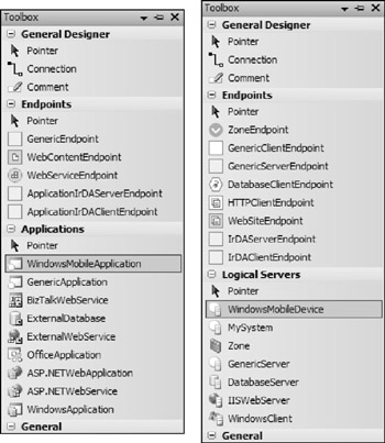
Figure 7-35
You have created a System Definition Model of a Windows Mobile Application that can be hosted on a Windows Mobile Device. It can consume WebServices through a WebServiceClientEndpoint and can communicate with other Windows Mobile Applications through IrDA. A constraint enforces that when this happens, the client will have a buffer that is at least as big as the buffer on the server side. However, if the Client endpoint on the application layer did not specify its buffer size, a flow makes sure that it is granted the maximum buffer size allowed by the hosting logical server.
When this Windows Mobile Application is hosted on a Windows Mobile Device, you enforce that the buffers used by the application do not exceed the maximum allowed buffer size.
In addition, the Windows Mobile Device must contain at least one CommonLanguageRuntime resource so that it can run managed code. It can contain multiples, but we enforce that it contains at least one.
On the application side, you have two settings on the application that specify what support the application delivers for some accessibility features: ScreenReaders and HighContrast mode. If either of these are not supported (i.e., set to false), a constraint you create yourself will be fired, informing the user that the application does not fully utilize and support accessibility. Through the Visual Studio ErrorList, the user will be capable of navigating to the offending settings through the Go To functionality for which your custom-defined constraint provides the names of the offending settings.
EAN: 2147483647
Pages: 220