Renderman
| The procedural paradigm took the computer graphics scene by storm with the introduction of Renderman. Renderman's goals were to offer a description language suitable to work with huge data sets, so real-world, natural scenes could be created. To achieve this complexity, the graphics process was broken into two major tasks: shape determination, which worked on the incoming geometry, and shading, which determined the visual appearance of the geometry. Renderman's engineers soon discovered that setting all shading and shaping properties explicitly would be prohibitive, both in terms of the size of the data set and the work required to create them. Thus, they allowed parts of the graphics pipeline to be substituted by small programs that acted much like filters on the data. Mathematical functions could be used to displace geometry and thus create the illusion of wrinkles, fractals could be employed to create visually rich and scale-independent texture maps, and so on. Take a look at Figure 21.2 for a sampler of Renderman shaders. Figure 21.2. Samples of Renderman shaders.
These user-provided programs were soon dubbed shaders because they were mainly used to create new texturing patterns and influence shading properties. However, there were six different types of shaders within Renderman:
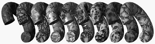
Light source shaders are used to create sophisticated lighting effects. They receive the position of a light source and the direction of a surface point from the light. Then, they return the color of the light originating at the source and striking that point. A good example would be creating a light bulb that's surrounded by a fine metallic mesh. We can create a light shader that emits different lighting intensities depending on whether the surface point is occluded by the mesh or not. Other effects, such as spotlights and bizarrely shaped lamps, could be created in the same way. Volume shaders are used to specify properties for volumes of space, such as fog. They receive the color, intensity, and direction of the light entering a volume and return the intensity and color of the light leaving that same volume. Transformation shaders are more related to geometry than to the shading process itself. They allow developers to apply transformations (both on an object and vertex level) to the incoming data stream. Transformation shaders receive one point and return a transformed point after all required operations are performed. If we apply the transformation to the complete object, rigid body transforms are achieved. By working on a vertex level, we can specify deformations, bendings, and so on. Surface shaders are used to specify the optical properties of surfaces: how they interact with light and so on. These shaders provide the best way to specify brilliance/metallic appearances as well as add bump maps. A surface shader often receives a point on the surface, the normal, and the lighting information. It then returns the reflected light. For example, bump maps can easily be added by perturbing the surface normal with some mathematical function (Perlin Noise would be very popular in this field), and then lighting the surface. Because the normal has been manipulated, the lighting will resemble that of an irregular surface. Displacement shaders are a surface shader's older brothers; they are more powerful and complex to use. Surface shaders can create the illusion of an irregular surface by using bump mapping. This technique does not actually manipulate the surface, but instead manipulates its normal. So how can we build real protuberances? How can we create a moon surface full of craters? Displacement shaders are the tools for the job in this case. They receive a point on the surface and several other details (such as the normal, partial derivatives, and so on) and compute a new, displaced point. This can be used to create fractal mountains from a single quad, just by supplying the fractal function to the shader. Imager shaders are used for color-based postprocessing. They receive floating-point pixel color values and return a set of values of arbitrary meaning as output. Thus, they can be used for effects like grayscale processing or color tinting, but also for other interesting applications. They can convert a vanilla RGB output into Hue-Saturation-Value (HSV) or any other format. They can produce most effects found in commercial image processing software, and so on. Renderman shaders were written in a C-like language and included a great library of useful functions. As an example, here is a surface shader that computes Lambert-like lighting by multiplying the incident light vector by the normal: surface IDez() { Ci = abs(normalize(N).normalize(I)); } Notice how Ci is the result of the shader, which receives N and I as inputs (even if they are not passed as parameters). The syntax is not very different from regular C code except for the first token, which is used to specify the type of the shader. Now, here is a more involved example that computes a bubbly displacement using the cellular basis function described by Steven Worley in his popular SIGGRAPH paper (see Appendix E, "Further Reading," and Figure 21.3). In this code, we will be passing three parameters that control how the displacement is applied: displacement IDbubbly(float mult=5,Nzscale=1,Kd=0.2,bubsize=1) { normal Nn = normalize(N); float a,b,c,bub; float dist, shortest=10000; point Po = transform("object",P)*mult; /*true cell center, surrounding cell centers, noised cell center*/ point trucell, surrcell, nzcell; vector offset; setxcomp(trucell,floor(xcomp(Po))+.5); setycomp(trucell,floor(ycomp(Po))+.5); setzcomp(trucell,floor(zcomp(Po))+.5); /*what is the shortest distance to a noised cell center?*/ for(a = -1; a<= 1; a+=1) { for(b = -1; b<=1; b += 1) { for(c = -1; c<=1; c += 1) { offset = vector(a,b,c); surrcell = trucell+offset; nzcell = surrcell + ((vector cellnoise(surrcell) -.5)*Nzscale); dist = distance(Po,nzcell); if(dist<shortest) shortest = dist; } } } bub = clamp(shortest,0,bubsize)/bubsize; P+= Nn*(pow(bub,2)-1)*Kd; N = calculatenormal(P); } Figure 21.3. Worley basis functions used to produce several textures, rendered using Renderman shaders.
Renderman shaders were compiled and stored as bytecode. Then, at render time, the appropriate shaders were executed as many times as needed to simulate the desired effects. Renderman shaders were never designed for real-time use. Render times were often in the "hours" magnitude per frame. Undoubtedly, shaders slowed down the rendering process, but the added flexibility and control made them a very interesting option. As a testament to Renderman's quality and flexibility, it is one of the leading rendering/scene description platforms used today, 15 years after its inception. The system gained widespread recognition with its use in movies like The Abyss, short films like Luxo Jr., and especially Tin Toy by Pixar; and it continued producing an endless list of blockbusters that have benefited from the flexibility of Renderman's shading language. In fact, you will soon see that Renderman has greatly influenced the way we perceive shaders today. In fact most real-time shading systems can be considered descendants of this cornerstone product. |
EAN: N/A
Pages: 261