| In typical campus designs, individual buildings connect to a central building by way of physical layer uplinks. You can create uplinks using optical wavelengths, where numerous wavelengths of light create separate logical channels on single mode fiber. Optical technologies including dense wavelength division multiplexing (DWDM) and Cisco coarse wavelength division multiplexing (CWDM) have major bandwidth benefits between buildings but at a much higher cost than more traditional campus cabling designs. A possible reason for the higher cost of using DWDM or CWDM is that you require dedicated physical layer optical networking gear to multiplex the wavelengths onto the single mode fiber. Traditional physical layer uplinks include dark fiber, copper cabling, or wireless connectivity between the buildings. You should centralize your user's access to corporate services, WAN connectivity to branch offices, and Internet access in the main campus building. Your users can connect through access switches at Layer 2 or 3 by routing or switching traffic to the central building through distribution switches located in the individual campus buildings. To provide resiliency for user access to centralized corporate resources, you can use Spanning Tree Protocol (STP), Etherchannel, or redundant routed links between the campus backbone and distribution switches. Figure 4-2 gives a fully redundant campus network design. Figure 4-2. A Typical Core/Distribution/Access Layer Campus Network Design 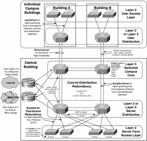
The central building contains the enterprise edge for incoming connections from the Internet and serves as the headquarters for satellite offices. You will learn about designs for enterprise edge and branch office networking in subsequent sections. To provide high availability in the campus backbone, the core and distribution layers contain multiple levels of redundancy as follows: Supervisor module redundancy Core Catalyst 6500/7600 switches are often used as distribution and core campus switches. These high port-density switches have the capacity for both supervisor module and switch-fabric module redundancy. You can achieve supervisor module redundancy within a single chassis by adding a second supervisor. You can also use two chassis with a single supervisor in each to achieve supervisor module redundancy. When you have multiple supervisors, if any single component of one of the supervisors fails, such as DRAM memory or embedded switch fabric, the other will automatically take over processing in a stateless fashion, normally within 3 seconds. The standby supervisor maintains identical configuration, routing tables, ARP caches, Routing Information Bases (RIB), and Forwarding Information Bases (FIB) as the primary supervisor, thereby enabling fail-over in the event of primary supervisor failure. Note Lower-end distribution switches, such as Cisco 4500 and Catalyst 3750 series switches, do not provide supervisor or switch fabric redundancy.
Switch fabric redundancy In older versions of Catalyst 6500 switches, the switch fabric was built directly in to the chassis backplane (known as an active backplane) or was available as a separate line-card module, called a switch fabric module (SFM). To provide switch fabric redundancy to an active backplane, a dual chassis configuration is necessary. For SFM redundancy, you can install two SFMs in a single chassis for redundancy. In more recent versions of the Catalyst 6500/7600 supervisor (that is, the Sup 720), the switch fabric is integrated into the supervisor module. With either the embedded supervisor switch fabric or a SFM line-card, redundancy is achieved within a single chassis. Note The switch fabric is where intelligent switching occurs between the individual line-card modules and supervisor module(s). In contrast, the backplane is the physical circuit board where the individual modules attach. If you have an SFM in a Sup II or integrated switch fabric in a Sup 720, the switch fabric and backplane are physically separate entities. To use the switch fabric, make sure that you install fabric-enabled line cards.
Layer 3 Routing redundancy Routing next-hop redundancy is performed using any dynamic routing protocol in Cisco IOS, such as IS-IS, EIGRP, or OSPF. Routers install multiple routes from the routing protocol FIBs and load balance between the routes using CEF per-destination or per-flow load balancing. You can achieve router default gateway redundancy for hosts using Hot Standby Router Protocol (HSRP). Layer 2 switching and link-level redundancy You can achieve uplink redundancy between access, distribution, and core switches using Etherchannel or STP. The Cisco Etherchannel supports link-level redundancy within the same switch module or across two or more different Ethernet modules. For rapid spanning tree convergence between users/servers and access switches, enable Cisco PortFast on the appropriate switch ports; between access and distribution switches, enable Cisco UplinkFast; and between core and distribution switches, enable BackboneFast. These protocols reduce spanning tree convergence time by bypassing particular states in the spanning tree's finite state machine. Power Supply redundancy The Cisco 6500/7600 provides space for dual power supplies within a single chassis. Alternately, two chassis with a single power supply in each achieves the same result.
|