Exploring CSS Global Server Load Balancing
| Cisco has numerous products capable of GSLB processing, giving Cisco the ability to fit GSLB functionality into virtually any content networking design. Due to the increase in demand for cross-site redundancy and RTT reduction, Cisco includes GSLB features in the CSS. Just as with the DD, you can configure your CSSs in your distributed network to act as DNS servers and respond to DNS queries for particular subdomains. Note You should consider using the GSS at the headquarters site in the place of the CSS, a consideration which is similar to that you make when working with the DD. The GSLB principals of the GSS are similar to those of the DD, CSS, and CSM. Refer to the product documentation on Cisco.com for more information on the GSS. CSS Multisite Load DistributionThe CSSs in your GSLB network can exchange load and status information for your virtual and real servers (you learned to configure ACA load in Chapter 10), using the Keep-Alive Appliance Protocol (KAL-AP) over reliable Application Peering Protocol (APP) connections. You must first create an APP peer mesh in order to disseminate information throughout your distributed network. You can then configure the A records on your CSSs for the virtual IPs (VIP) that they serve and NS records to delegate authority to other lower-level CSSs. The CSSs exchanges these A and NS records with one another using APP, in addition to the load and status information via KAL-AP mentioned previously. When a CSS receives an A record request from the TLD or IDNS server via the DNS infrastructure (with round-robin load balancing, if necessary), it determines the best site using the load and status information learned through APP. The CSS then responds to the client's DNS server with the A record of the best site. For example, say that the subdomain www.cisco.com is replicated at two sites, with three real servers at each site. You should delegate the subdomain www.cisco.com to the CSSs across the two sites, by updating your intermediary DNS servers with two NS records associated with the two content switches, which you learned how to do previously. You then configure your CSSs to respond to queries to the subdomain www.cisco.com, as Figure 12-7 illustrates. When the intermediate DNS server receives the client DNS request, it chooses either CSS using round-robinsay that it chooses CSS-B for the request in this example. When CSS-B receives the request, it determines that CSS A is more capable of fielding the request, based on the load of the real servers for the VIP. As a result, CSS-B responds to the client's DNS server with the VIP of CSS-A. The client DNS server forwards the A record to the client, which uses the VIP address of CSS-A for the connection. Figure 12-7 illustrates this example. Figure 12-7. GSLB Using the CSS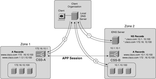 Note The DD does not support APP and therefore do not have the ability to track the load of remote servers to base the load balancing decision on. The CSM does support APP for use with GSS. To configure the zone for your individual sites, use the following command on each CSS: dns-server zone zone_index {tier1 | tier2 {"description" {weightedrr | srcip | leastloaded | preferlocal | roundrobin | ip_address {weightedrr | srcip | leastloaded | preferlocal | roundrobin } {weight}}}} You must specify the tier and the load-balancing method for the zone with this command. You can create nested zones using tiers in a CSS proximity environment. You will learn about CSS proximity later in this Chapter. If you configure the least-loaded load balancing method, you must configure ACA for your real servers as you learned previously in Chapter 10. To modify the way in which the CSS uses the load information, you can use the command dns-server zone load [reporting | frequency seconds | variance number] The frequency keyword modifies the time between processing the load information and advertising it to APP peers. The variance keyword modifies the range of load numbers that the CSS considers different. This number is similar to the load step, which you learned about in Chapter 10. Example 12-3 shows you a sample CSS GSLB configuration. Notice that you do not manually configure the A records for the other sites, because the CSS advertises these to one another using APP. Example 12-3. Sample GSLB Configuration Using the CSS
The configuration in Example 12-3 creates an APP connection between the two sites, "Site A" and "Site B," across which it sends KAL-AP keep-alive messages. If you do not configure KAL-AP with the kal-ap keyword in the dns-record command, the CSS uses ICMP keep-alives (KALICMP) by default. Example 12-3 uses WRR to distribute the load across the two sites. APP-UDP is required for the CSS Proximity Database (PDB) that you will learn about later. Additionally, you can specify the TTL for the A record (that is, 3600 seconds in this example) after the domain name in the dns-record a command. The single keyword specifies that the CSS will return only a single A record to the client DNS server. If you instead specify multiple, the CSS will return all available A records (there are two of them in this example) to the client DNS server. Then the client DNS server can cache the multiple A record answers for the time specified in the TTL and round-robin load-balance subsequent requests for the domain. If you enable multiple records, the client DNS server may load balance clients to sites that are unavailable. Be sure to understand how your sites behave before enabling multiple records. CSS Proximity-Based Load BalancingThe CSS uses a stateful Proximity Database (PDB) to store RTTs for client DNS servers, resulting in better overall response times for clients than the stateless proximity DD solutions that you learned about previously. In a CSS proximity configuration, each site contains a PDB and a Proximity DNS (PDNS) server. PDNS servers maintain the health of their local virtual servers and advertise their health to peer PDNS servers located at different sites. For the PDB to work efficiently, make sure that your DNS requests are load-balanced between the PDNS servers by the DNS infrastructure (that is, by the TLD or your IDNS servers). Figure 12-8 illustrates the PDB flow. Figure 12-8. Proximity Database DNS Resolution Flow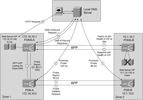 When a PDNS server receives a DNS request, it sends a lookup request via APP-UDP to the PDB for the site closest in proximity to the requesting client DNS server. If the PDB does not have an entry for the client IP, it coordinates a probe of the client DNS server between itself and the other sites in the GSLB (Steps 3 and 4 in Figure 12-8), through a mesh of peer APP connections. The PDB server sorts the resulting list of RTT values from its peers and sends the list to the requesting PDNS server. When the PDNS server receives the ordered list, it determines the health of each entry through its APP peer connections (Steps 7 and 8 in Figure 12-8) and decides which site is best suited for the request. The example in Figure 12-8 takes the following steps for a client A record request for "www.cisco.com."
The CSS determines proximity using ICMP or TCP probes, in the same fashion as the DD determines proximity using ICMP and TCP probes. That is, with TCP probes, the CSS sends a TCP SYN/ACK to port 53 of the client's DNS server. The client's DNS server recognizes the faulty TCP segment and sends a TCP RST to the requesting PDB, enabling the PDB to calculate the RTT. If the above PDB probes fail for any reason, the PDNS chooses a configurable default load-balancing method for the request, such as least connections. For example, if the client DNS server is behind a firewall that blocks TCP SYN/ACK segments without first receiving a TCP SYN segment, TCP probes may fail to a client DNS server. Note Because the Boomerang protocol sends only DNS responses, it is unable to determine the RTT to client DNS servers. Therefore, you cannot use Boomerang with PDB. However, you can use the Boomerang protocol outside stateful proximity with the CSS functioning as a Content Routing Agent (CRA), but you need the Global Site Selector (GSS) to coordinate the Boomerang operation. You will learn how to configure your CSS as a CRA in the section called "Configuring Content Routing Agents." in this Chapter. The PDBs periodically synchronize their RTT information over the APP peer mesh to retrieve complete ordered lists of RTT values for every request. In this example, after synchronization, both PDBs have the RTT that the other PDB calculated for the client DNS server; that is, they will both have the ordered list [(2, 80) (1, 120)]. If later a DNS request for the domain from the same client DNS server is sent to PDNS-B by the DNS infrastructure, PDB-B will not have to coordinate probes between itself and PDB-A. A PDNS is not required at every site, but PDBs are in order to probe client DNS servers during initial RTT calculations for a particular client DNS server. If you do not have a PDNS server at every site, make sure that the DNS infrastructure has NS records for only those sites that contain a PDNS server. Figure 12-8 illustrates a fully redundant solution, with both PDNS and PDB servers located at each site. To configure your PDBs, you can use the configuration in Example 12-4. Example 12-4. Configuring the CSS Proximity Database
To configure your PDNS servers, you can use the configuration in Example 12-5. Example 12-5. Configuring the CSS Proximity DNS Server
You create the zone using the dns-server zone command, similarly to the way you configure the zone in nonproximity configurations, but in a proximity configuration you must specify the IP address of the PDB. Additionally, this example uses KAL-ICMP to determine the health of the VIPs on the peer PDNS servers (that is, Steps 7 and 8 in Figure 12-8). Multitiered ProximityTo scale your CSS proximity environment, you can nest additional zones within your existing zones. To create a nested zone, you must assign the PDNS servers of the nested zones as a secondlayer tier server using the tier2 keyword in the dns-server zone command. You must also create NS records for the second layer tier on your Tier 1 PDNS CSS, thus delegating the required domains to the Tier 2 PDNS CSS (using the dns-record ns command). When your Tier 1 PDNS CSSs receive a client DNS request for a Tier 2 domain, they perform a recursive DNS lookup by issuing an A record request to the Tier 2 PDNS CSS you specified in the NS record. When the Tier 2 PDNS CSS receives the request, it performs the same flow that you learned previously in Figure 12-8 among its Tier 2 APP peers. When the Tier 2 finds the best-suited A record, it stores the A record locally in its PDB server and sends the A record to the Tier 1 PDNS server. The Tier 1 PDNS server then responds to the client DNS server with the A record. Configuring Content Routing AgentsLike the CSS, the Global Site Selector (GSS) maintains a PDB, but behaves like the Distributed Director in determining proximity. That is, the GSS uses DRP to instruct IOS-based routers to probe client DNS servers for calculating RTTs to store in the PDB. The GSS also supports Boomerang DNS racing but, as you learned, Boomerang precludes calculating RTTs; therefore, the GSS PDB cannot work in conjunction with Boomerang. Hence, you must use CRAs on a CSS or a DRP agent on an IOS router at each site for Boomerang DNS racing. You learned how to configure DRP for Boomerang previously. However, to enable the CSS as a CRA for GSS Boomerang DNS racing, you can use the configuration commands dns-boomerang client enable dns-boomerang client domain www.cisco.com 10.1.10.100 Note For information on configuring your GSS for GSLB, refer to its product documentation on Cisco.com. |
EAN: 2147483647
Pages: 178