9.4 Uh-oh We ve Been Given the Wrong Directions
9.4 Uh-oh We've Been Given the Wrong Directions
On rare occasions (like every project we've ever worked on!) the customer changes his or her mind, or wants extra functionality. This happens because the customer doesn't fully comprehend the system until seeing it and using it. This will result in a change in requirements. You can regard this as either an opportunity to shine or an opportunity to have a cardiac arrest.
The customer doesn't like the concept of entering data by dialog boxes, so he or she has decided to automate the test by reading the BCD inputs to the LCDs, provided by a test port. There are four digits of four bits for each card. With some digital multiplexing we can switch between displays on the unit under test and then between units. This can be done with a cheap Digital I/O card and a little bit of circuitry .
| Port 1 Bits 1 “4 | - Digit 1 (least significant digit) |
| Port 1 Bits 5 “8 | - Digit 2 |
| Port 2 Bits 1 “4 | - Digit 3 |
| Port 2 Bits 5 “8 | - Digit 4 (most significant digit) |
| Port 3 Bit 1 | - Display 1 & 2 Switch |
| Port 3 Bits 2 “5 | - Unit Selector |
What do we have to change and where? Well, we know that all the tests are in the hardware component, so we can start there. Note how strong cohesion cuts down on all the hunting around for affected VIs.
So, at the hardware component we don't need to change the commands, and the public interface remains the same. As far as any VIs are concerned nothing has changed.
The actions affected are:
Get Chan1 Display Reading
Get Chan2 Display Reading
The changes are shown in Figures 9.39 and 9.40.
Figure 9.39. Hardware before changes.
Figure 9.40. Hardware after changes.
Three new actions have been added to the control component to set the display to be read (1 or 2), and to switch in the digital multiplexer for the required test position. We've also improved the read component slightly by combining the "Get Display Reading" commands into one generic command.
Figure 9.41 shows the new control component additions.
Figure 9.41. New control actions.
And you'll notice that a new DIO component has been created. Figure 9.42 shows what it looks like inside.
Figure 9.42. DIO component.
The read component changes consist of deleting the "Get Chan2 Display Reading" case and its corresponding command from the Read Commands Strict Type Def., and changing the "Get Chan1 Display Reading" to just "Get Display Reading".
The visual component is then modified to include the new DIO code for reading the BCD inputs to the displays. These changes are shown in Figure 9.43. For convenience we've committed a bit of naughtiness here; we're going to use the DIO component in the read component as well. Oh well, rules are meant to be broken. We should move the DIO component from its private directory to a public directory though to indicate that it is now being shared.
Figure 9.43. Visual component.
This clearly demonstrates the improved maintainability gained by incorporating information hiding, strong cohesion, and loose coupling. The result is that the robustness of the system has not been compromised by a reasonably sized design change. For the sake of brevity we'll only discuss the impact of the next change.
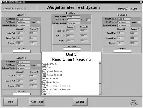
The customer would like a history of the actions of each test in the sequence displayed on the front panel. What we could do is shrink the current status indicator and add another new indicator called History. If you set the text small and use the Courier font it will look somewhat like a printout.
To implement it you will need to do the following, as shown in Figure 9.44.
Figure 9.44. New History Display.
Add two new commands to the UI controller commands and settings controls: "Clear History" and "Add to History". You do this by adding the commands to the end of the respective enumerated types. Duplicate the cases in the UI Controller component and implement the new commands.
In the Widgetometer User Interface VI add the new cases to the case structure in the Control Displays loop and put in the string manipulation required. Figure 9.45 shows an example.
Figure 9.45. Add History Display action.
You can then either send all calls to the hardware component to this display, or format something nice in the test executive and send that. The test executive option is demonstrated in Figure 9.46.
Figure 9.46. Update History in test executive.
Review Sections 9.2.4 and 6.2 for more information on the ease of updating displays by implementing LCOD message-sending techniques.
| |
| Top |
EAN: 2147483647
Pages: 66