4.2 Design
The design of your system has important implications throughout the life of the project. LabVIEW is a software language like any other, the rules and lessons learned by other software practitioners are just as applicable in LabVIEW as they are in C, Pascal, ADA, SmallTalk, Java, or any other language. The graphical nature of LabVIEW gives your source code high visibility, making bad design harder to hide!
Your source code is a reflection of your programming ability and a public document of your professionalism . Your most critical audience will be the engineer who picks up your project after you.
The costs of poor design are:
-
Missed deadlines
-
High maintenance costs
-
Poor reliability
-
Unpredictable application behavior
-
Stressed customers
-
Bankruptcy, broken homes , misery, and pestilence
4.2.1 Object Oriented Design (OOD)
If you have not heard of Object Oriented Design (and associated languages), then it is probably best you put this book down and start getting out more, or maybe consider an alternative career. An OO approach to software has become a very religious experience. In some quarters unless a language or technique is claimed to be OO, it is dismissed. Let's take a closer look.
Classic OO Lesson
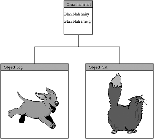
Object Orientation is good because you can model real-world objects using it. These principles are so easy to understand you probably understood them when still in the womb. Even a small piece of fruit could understand them. The emperor's new outfit looks fantastic!
The picture in Figure 4.2 explains it all, now go forth and write great software. But, you could also have dogs and cats as:
class : pet
class : animalsThatSitInYourGarden
class : thingsThatMakeMeSneeze
subclass : Canis and Felis
Figure 4.2. Typical OO explanation.

Although the picture and description accurately model the complexities of my dog, she is exceptionally stupid, and they do little to illustrate the real-world complexities of designing software. Modeling complex systems using OOD is still complex, we want our money back!
Flippancy aside, OO Design, Analysis, and Programming have brought a lot to the table of software design. The characteristics of OO encourage modularity, encapsulation, information hiding, loose coupling, and strong cohesion. These are all the things we want for our components . However, a badly designed OO program is as difficult to maintain as a badly designed procedural-based program.
So what do we do with OO in LCOD? We use the parts of OO that help us the most. To define OO concepts would be a whole other book, so we will try and keep this brief and simple. As you should already know the pivotal step in OO design is the identification of classes. Classes are defined by the identification of real-life and abstract objects, the operations and methods that the class will react to, and the data it will operate on. Typically, you never modify the data that belongs to a class, you only request that the class carries out the predefined operations on it. This is exactly the behavior we want our components to have. When we define a component we will hide the data implementation behind an interface; thus anyone calling our component can only interact with the data and services provided by the component via the defined interface (cohesion, coupling, and information hiding).
How do we identify possible components? A technique often employed for identifying classes is something called a noun-verb parse. Basically, look at the requirements and consider each noun and verb as a possible candidate for a class. That all may sound a bit like hard work, but you probably already do it anyway without realizing . An obvious example would be oscilloscope. If you see this noun in the requirements then it is a prime candidate for a class called oscilloscope, or in our case a component. We could offer loads of examples that exhibit nouns and verbs, but apart from being a bit boring it is probably better for you to go back and examine previous projects to see if you have already been doing this. Bear in mind that this is also iterative, and you probably won't get all your components in one go, especially in large projects.
Another technique that is more relevant to the projects you will most likely be working on (test, monitoring, or control systems) is to look at the physical entities that will exist in your system. Measuring devices, environmental control, and transducers are all prime candidate components (or classes).
A great benefit to us is that when we have identified our components, future change (and there will be plenty as the project progresses) is confined to the components themselves , whereas the services they provide will remain relatively static. This means that changes are insulated from the other components that use their services. On the face of it this probably does not sound like such a great feature, but it is probably the biggest payback from adoption of LCOD.
The one thing that OO does is it allows us to look at the problem at a high level of abstraction, but is not so good when coming to low-level structuring.
4.2.2 Top-Down Design
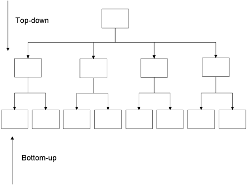
Top-down design sounds like you start at the very top of your application and start decomposing it into routines. This can be the case, but it is just as applicable when we take our components, which we have identified using OO techniques, and want to decompose them into the modules and inner components that will make them function. The main thing here is that we as mere humans can only concentrate on a certain amount of detail at any one time. Thus, decomposing in this manner makes the task more manageable for us, without having to deal with too much detail.
The basic way we use top-down design is to take whatever we want to decompose and look at it from the top, split it into components and look at those new components, then split them, and so on. When do you stop? Probably when it would become easier to write the code than carry on decomposing.
A prime example of where top-down design comes into its own is in designing menus . In more complicated applications there can be a complex menu system that allows the user to navigate around the application.
4.2.3 Bottom-Up Design
We consider this to be the opposite of top-down design, how obvious is that! Well, maybe not quite that obvious. Sometimes top-down and OO techniques can be at too high a level in abstraction, so to get started we use what we may already know. For instance, we know all the hardware that we are going to use, but we're not sure how it will be used by the rest of the system. By looking at what we have available we should have a better chance of figuring out what services we are able to provide. The key concept here is that we decompose using top-down but compose using bottom-up. Or, in top-down we start at the sharp end and bottom-up we start at the fat end (no pun intended). Figure 4.3 puts this into a graphical context.
Figure 4.3. Top-down and bottom-up designs.

Either way, both bottom-up and top-down are extremely useful in attacking the design problem. Sometimes you can try and tackle the problem using OO, not get it right, then try top-down, not get it right, and then try bottom-up. Essentially, they all give you the tools to attack the problem from all angles.
So, we've covered a little OOD, a little top-down, a little bottom-up, but what about a little experience?
4.2.4 Design Patterns
How many times have you had a design d j vu ”that feeling that you have solved a problem before not knowing where or how? [1]
” E. Gamma, R. Helm, R. Johnson, J. Vlissides, Design Patterns: Elements of Reusable Object-Oriented Software
[1] From Gamma, Helm, Johnson, Vlissides, Design Patterns: Elements of Reusable Object-Oriented Software , 1995 by Addison-Wesley Publishing Company. Reprinted by permission of Pearson Education.
Experience is something, in our humble opinion, that cannot be argued against as being the major contributor in solving problems. Often the ability to solve a problem is based on our memory of previously solved problems. This means that we recognize similarities between the problem we have solved previously and the problem we find before us. This is because the problems have a pattern.
Recognizing patterns in software is something most people will do quite naturally without realizing it. However, realizing it, documenting it, and then using it has huge payback. Most discussions of patterns in software are confined to OO, which is a shame since patterns are applicable to any software and design methodology.
So what is a pattern?
Dictionary Definition
Pattern ” A model or original used as an archetype . A plan, diagram, or model to be followed in making things.
Our Definition
Design Pattern ” A pattern is the repeated occurrence of a solved problem.
Giving your software modules a limited interface by using message sending gives uniformity to your code that allows patterns to be observed . This observation of patterns in our code came as a direct result of using LCOD. We discovered that even working separately and from scratch on different systems there were still marked similarities in our code.
There are low-level patterns (a state machine is a design pattern), but we are going to concentrate on the higher level patterns that can be applied to complete systems.
So what do you get from the identification and use of patterns? It has been said that the difference between good and bad designers is that a good design does not solve every problem by applying first principles. They cheat!
Following is a list of what using patterns can do for you:
-
Reuse of design
-
Reuse of components
-
Questions to ask (helps with requirements gathering)
-
Cycle of reuse. The use of patterns encourages the reuse of components. (You can add more functionality to reused components because they are identified as useful and usable, and you already have the context in which they are going to be used.)
Take a test system for example, if you break it down right you will find it is very similar in structure to most other test systems. Each test system has a lot of scope for reusing code. For example handling the User Interface, Handling Data, Reporting, Error Handling, and executing the program. To illustrate the advantages this brings let's look at each item in the list above.
Reuse of Design
It is much easier to edit a design than to create a new design. Most novels are actually written to a pattern (tragic hero, triumphant underdog, etc.). Sometimes the plot pattern is more obvious than others, but it is still there.
Reuse of Components
Reusing the design simplifies and enables the reuse of components. Plugging in and adapting existing components is usually easier when there is an existing proven framework to hang them from.
Questions to Ask
This is a good one. If you have a design pattern and a set of components that have actions and attributes to define you can use this as a basis to ask very specific questions of your customer. Requirements are far easier to gather when based on specifics.
Cycle of Reuse
Applying a reusable design encourages the reuse of components, and reusing components improves the visibility of design patterns.
4.2.5 Pattern Examples
Top Level : User Interface>> System>>Hardware
User Interface : Menu Submenu Tree Pattern
Data Handling : Section Keyed Data Handling Pattern
Hardware : Control>>Drive>>Read
We'll look briefly at a couple of pattern examples next .
UI Controller>>Message Queue Pattern
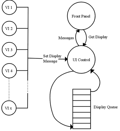
One of the problems with LabVIEW is that it is difficult to decouple the display from the actual program execution. This tends to make diagrams flatter and larger than they should be. It also encourages the passing of data down the hierarchy where it isn't necessary. This results in inflexibility in design. The UI Controller>>Message Queue Pattern (Figure 4.4) draws its inspiration from the tried-and- tested techniques employed in most Graphical User Interfaces (GUIs), which is the passing of display states as messages onto a message queue. The advantages of doing it this way are as follows :
-
The display can be changed more or less anywhere in the program hierarchy.
-
The User Interface can be designed and tested isolated from the rest of the program (by using a simple test stub).
-
The definition of the display is a matter of describing all the different states of the display.
-
Adding new functionality does not weaken the structure of the program. It's just another message and corresponding action.
Figure 4.4. UI Controller>>Message Queue Pattern.

The one disadvantage is the additional memory and processing overhead required, but this would only occur on very slow computers, and there are strategies that can be used to reduce the amount of messages to economic levels.
Control>> Drive>>Read Pattern
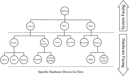
Regarding the method, Figure 4.5 describes the Hardware actions in gradually more detail, starting with the Hardware VI, which has commands that describe the tests or actions being conducted in system facing language. A good example would be "Read Signal Response" for unit 1. This may involve switch setting, signal generation, power supply setting, and retrieval of a waveform from an oscilloscope. But as far as the Hardware VI is concerned it is a simple command. Hidden beneath the simple interface of the Hardware component will be some kind of state machine. One of the states will correspond to the request to read the signal response for the unit in question. It will then use a combination of the Control, Drive, and Read components to connect the unit and test equipment, set the power supply and generate the signal, and finally read and return the measured value.
Figure 4.5. Control>>Drive>>Read Pattern.

Going to the next level then introduces the Control, Drive, and Read VIs. Sometimes you won't need all of them, so exclude any that aren't applicable, we don't mind. Again the commands you define for these components will look toward the system. So in the example mentioned previously the Control component would have commands for connecting the Unit, the PSU, Signal Generator, and the selected measuring equipment to the test system. The Drive component would have commands to provide the signal and set the PSU. Finally, the Read component would have commands to return the required measurement.
Control : Environmental Control, Switching
Drive : Signal Generation, Power supply setting
Read : Multimeter, Oscilloscope, Thermometer
A complete discussion of patterns would fill a whole other book (see the footnote at the beginning of this section). However, understanding that they exist and applying them should become second nature.
| | |
| Top |
EAN: 2147483647
Pages: 66