Conventional Driver Event Logging
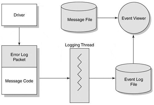
 [oR] [oR] The original Windows NT architecture includes a mechanism that allows software components to keep a record of noteworthy events. This event-logging capability can help monitor the behavior of software that is under development or in production. How Event Logging WorksThe developers of Windows NT had several goals for the event-logging architecture. The first was to provide subsystems with the unified framework for recording information. This framework includes a simple yet flexible standard for the binary format of event-logging entries. Another goal was to give system administrators an easy and consistent way to view these messages. As part of this goal, viewer utilities must be able to display event messages in the currently selected national language. Figure 13.3 shows the event-logging architecture. Figure 13.3. Event-logging architecture. The overall process for the generation and display of event messages is described by the following:
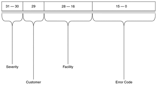
Working with MessagesAs just described, a driver does not include the actual text for its messages in an event-log entry. Instead, it identifies messages using code numbers. The text associated with these code numbers takes the form of a message resource stored somewhere on disk. This section describes how these message code numbers work and explains how to generate custom message resources. The code number identifying a specific message is a 32-bit value consisting of several fields. Figure 13.4 shows the layout of a message code. Figure 13.4. Layout of a message-code number. The Severity field of a message code is a 2-bit field which signifies success (0), warning (2), error (3), or informational (1) status. The I/O Manager provides a number of standard messages that a driver can use. The header file, NTIOLOGC.h, defines symbolic names for these message codes, all of which begin with IO_ERR_. The file can be browsed for a complete list of standard messages. To use standard messages, a driver must be included in the list of event-logging system components within the Registry. The actual text file for these shared messages must also be supplied (IOLOGMSG.dll). The procedure for performing this registration is described later in this chapter. A driver can also supply custom message text. To do this, the following steps should be followed:
Writing Message Definition FilesTo use the MC utility, a definition file describing all the driver messages must be written. This definition file is divided into two major sections.
The message text itself begins after the last keyword. The text of a message can occupy several lines. A message is ended with a line containing only a single period character. The message compiler ignores any white space or carriage returns in a message definition. Various escape sequences (listed in Table 13.19) can be included in the body of the message. The %1-%99 escape codes represent Unicode strings (embedded in the event log packet) that are inserted in the message when the Event Viewer displays it. If a kernel-mode driver associates an event packet with its device object, %1 will automatically contain the OS name of the device; if the driver associates the packet with its driver object, %1 is blank. In either case, the first real insertion string is %2, the second %3, and so on. A Simple ExampleHere is the message definition file for a simple example.
HEADER SECTIONThe first part of the message definition file contains header information. MessageIdTypedef = NTSTATUS SeverityNames = ( Success = 0x0:STATUS_SEVERITY_SUCCESS Informational = 0x1:STATUS_SEVERITY_INFORMATIONAL Warning = 0x2:STATUS_SEVERITY_WARNING Error = 0x3:STATUS_SEVERITY_ERROR ) FacilityNames = ( System = 0x0 RpcRuntime = 0x2:FACILITY_RPC_RUNTIME RpcStubs = 0x3:FACILITY_RPC_STUBS Io = 0x4:FACILITY_IO_ERROR_CODE MyDriver = 0x7:FACILITY_MY_ERROR_CODE ) MESSAGE SECTIONThis section contains message text and identifiers. It defines the actual text to be associated with a message code number. MessageId=0x0001 Facility=MyDriver Severity=Informational SymbolicName=MSG_LOGGING_ENABLED Language=English Event logging enabled for MyDriver. . MessageId=+1 Facility=MyDriver Severity=Informational SymbolicName=MSG_DRIVER_STARTING Language=English MyDriver has successfully initialized. . Compiling a Message Definition FileOnce written, the message definition file must be compiled using the MC tool supplied with the Platform SDK and the DDK. Table 13.20 shows the syntax of the MC command. After a successful message definition file is compiled, the following files are generated:
Adding Message Resources to a DriverIn most cases, the output from the MC compilation is included in the driver executable itself. Simply including the name of the .RC script file within the driver project (makefile) is sufficient. Registering a Driver as an Event SourceThe system Registry serves as the linkage between an event source and the message files needed to translate any message codes appearing in its log entries. To register a driver as an event source, the following changes must be made to the Registry under HKEY_LOCAL_MACHINE\System\CurrentControlSet\Services\EventLog\System:
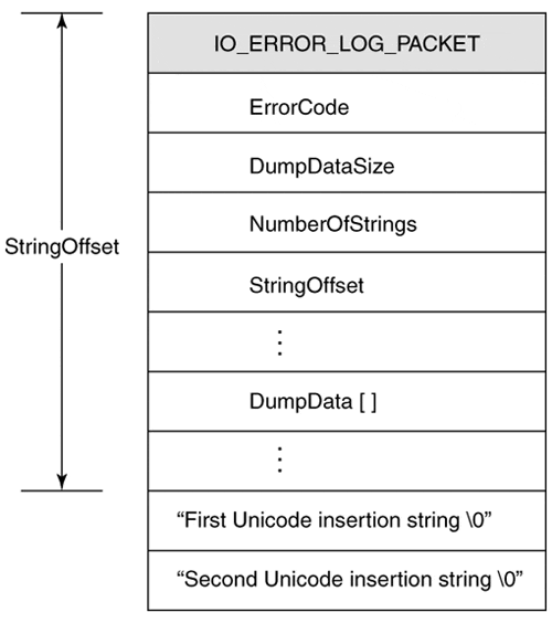
Generating Log EntriesCode to actually generate a message is relatively straightforward. It involves allocating an event message packet, filling it, and sending it to the system logging thread. It is common practice to trigger the verbosity of driver event generation based on a driver-specific registry value. For example, under the Parameters subkey of the driver's service key, a value called EventLogLevel might determine the number and extent of actual messages generated. Thus, during debugging or during a production incident, full event logging could be enabled. Allocating an Error-Log PacketWhen a driver uncovers an event that needs reporting, it must prepare an error-log packet. There are three sections to an error-log packet.
Both the dump-data and insertion strings are variable in length and are optional. Figure 13.5 shows the structure of an error-log packet. Figure 13.5. Layoout of an error-log packet. Before an error-log packet can be allocated, its size must be determined. Sufficient space must be allocated for any dump-data and insertion strings. The size of the packet can be calculated using a variation of the following piece of code: PacketSize = sizeof( IO_ERROR_LOG_PACKET ) + (sizeof( ULONG ) * (DumpDataCount-1)) + sizeof( InsertionStrings ); The requested size of the packet cannot exceed ERROR_LOG_MAXIMUM_SIZE. The IoAllocateErrorLogEntry, described in Table 13.21, is used to allocate the packet. As seen, the packet can be associated either with the Driver object or with a specific Device object. The choice determines how the Event Viewer utility displays the message. Initialization and shutdown messages are typically Driver-level messages, while problems involving specific IRPs or hardware should be associated with a Device object. Notice that the use of IoAllocateErrorLogEntry requires a thread context at or below DISPATCH_LEVEL IRQL. Therefore, if an ISR needs to log an error (a common occurrence), a CustomDpc routine must be used to perform the actual work.
Logging the ErrorOnce the packet is allocated, all the relevant fields must be filled. In addition to the fields listed in Table 13.22, any driver-specific data and strings must be added. When the packet is ready, use IoWriteErrorLogEntry to send it to the system logging thread. The packet is no longer owned by the driver once this function is called, so the driver must not be touched again. As with packet allocation, this function can only be used at or below DISPATCH_LEVEL IRQL.
|
EAN: 2147483647
Pages: 156