2.1 Networking in front of the Server
| The front of the server faces outward toward the user community via a network interface. Typically, you network dispersed computer resources across an enterprise by using Ethernet as the physical transport and TCP/IP as the networking protocol. The nearly universal adoption of Ethernet and IP is the result of a long natural selection process against competing transports and protocols. Token Ring, for example, provided an orderly and stable networking solution, but it could not survive the economies and simplicity offered by Ethernet. SNA once dominated enterprise data communications networks, but in the end it succumbed to open systems IP networking. Networks can be defined by protocol (for example, an IP network) or by geography (for example, a local, metropolitan, or wide area network). Regardless of the specific means employed to move data from one device to another, network infrastructures generally follow a hierarchy that extends from the physical layer up through the end-user application. The abstract reference for this hierarchy is the OSI (Open System Interconnection) Reference Model. Although individual network protocols may deviate from the OSI Reference Model, it is a useful structure for understanding the basic features of networking. As shown in Table 2-1, the OSI model divides networking into seven functional layers. Although these layers are interdependent, the model gives you the flexibility to substitute one implementation for another (such as Ethernet for FDDI) within a layer. In this way, the upper-layer functions can be supported by a wide variety of lower-layer implementations. An e-mail carried in an IP datagram, for example, can be consecutively transmitted over Ethernet, Frame Relay, Asynchronous Transfer Mode (ATM), and back to Ethernet at the destination. Layers 1 and 2 in this case would change at each step, and the content of the upper layers would be preserved during transit. As user data is passed down by an application for transmission across the network, it is wrapped in successive envelopes of information, roughly corresponding to the layers represented in Table 2-1. A file transfer, for example, would acquire an information envelope on the file's format (layer 6), information useful for maintaining the file transfer session between sender and recipient (layer 5), information for acknowledging receipt of blocks of the file (layer 4), network addressing information (layer 3), information about the type of media on which the data was originated (layer 2), and encoding to place the data on the physical transport (layer 1). At the receiving end, each envelope would be verified and removed by the target until the data that composed the original file could be passed to the upper layers for reconstruction.
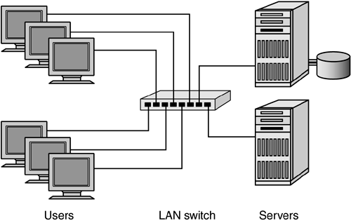
Network protocols such as TCP/IP enable data transfer for both local area and wide area networks. In complex networks, data wrapped in network protocols may pass through multiple LAN and WAN segments before arriving at the final destination. Each routing step through a network segment is generically referred to as a hop. As shown in Figure 2-1, a single LAN segment enables multiple users to access shared resources such as file servers or printers. Multiple LAN switches can be connected to scale to higher concentrations of devices. Figure 2-1. A LAN segment using switched Ethernet
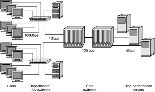
Local area networks are typically built to link computers at a single site, such as an office building or data center. LANs provide connectivity over a variety of physical links, including twisted-pair wiring, fiber optics, coaxial cable, and wireless transmitters. These media correspond to the first layer of the OSI Reference Model. The most prevalent LAN transport is Ethernet over twisted-pair copper wiring. Ethernet transmission rates are 10Mbps (megabits per second), 100Mbps (also known as Fast Ethernet), and 1,000Mbps or 1Gbps (Gigabit Ethernet). 10Mbps and 100Mbps speeds are most commonly used for attachment of individual PCs or workstations, with effective data rates of slightly more than 1MBps (megabytes per second) and 12MBps, respectively. Gigabit Ethernet is used primarily for high-performance core networks, and for attachment to file and application servers. The original 10Mbps and 100Mbps Ethernet LANs often supported multiple devices on a single shared bandwidth by use of hubs. Today, most Ethernet deployments use Ethernet switches for dedicated bandwidth to each device. Ethernet is ubiquitous, and modern office complexes are prewired with both phone and Ethernet jacks in every office and cubicle. These local user connections are typically run to Ethernet switches, which may, in turn, use Gigabit Ethernet uplinks to tie the local segment into a Gigabit Ethernet backbone. High-port-count (128, 256, or higher) backbone switches enable enterprise networks to allocate connections to users and servers and to manage bandwidth based on application requirements. In addition, most vendors of Gigabit Ethernet switches offer 10Gbps Ethernet ports for interswitch links. High-performance 10Gbps Ethernet links allow scaling to hundreds or thousands of devices in a single network. As shown in Figure 2-2, if you want to scale networks to efficiently support higher populations of devices, you must manage bandwidth. If you restrict the network to a single speed, bottlenecks will occur as more users attempt to access shared resources. Because Ethernet offers deterministic bandwidth in powers of ten, it is possible to design scalable nonblocking infrastructures. In this example, users are attached by Fast Ethernet, and the departmental LAN switches are attached to the core by Gigabit Ethernet. The core itself can be built with one or more 10Gb interswitch links to provide a high-performance LAN backbone. Figure 2-2. Scaling the network using departmental and core switches
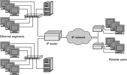
Ethernet LANs are normally limited to a single building or campus. To share computer resources with remote sites, wide area networks (WANs) use telecommunications lines, microwaves, or satellites to transmit data. Routers are an essential ingredient of both LANs and WANs. As shown in Figure 2-3, routers sit on the local LAN segment and move data from one local segment to another and to the telecommunications carrier (AT&T, Qwest, etc.) for remote sites. This connection to the carrier is often depicted using a cloud symbol because any number of microwaves, satellites, or optical switched networks could be used to move data from the local site to the remote. On the other side of the cloud, a communications line connects to a remote router, which in turn serves the remote computer users. As with Ethernet, WAN topologies provide access methods to ensure the orderly transmission of data from one site to another. Various communications methods for the WAN are specified by Point-to-Point Protocol (PPP), Frame Relay, ATM, and Packet over SONET (POS). Figure 2-3. Routers in LAN and WAN configurations
In Figure 2-3, the connectivity provided by routers enables users in one local network segment to access networked resources in another local segment. The ability to segment a single network into multiple parts improves the performance and efficiency of each segment while still allowing communication between them. Segmentation also insulates the network as a whole from data-link layer broadcast storms generated within a single part of the network. Traffic in a single network segment is performed at layer 2, whereas layer 3 route processing is required only for traffic destined for another segment. If, alternatively, the entire network were one large layer 2 segment, it would be vulnerable to disruptions. Layer 2 LAN bridging of the 1980s exposed this vulnerability as networks grew to larger populations and eventually were displaced by layer 3 IP routers. The significance of network segmentation for SANs is discussed in Chapter 4 (on Fibre Channel topologies) as well as Chapter 7 (on IP storage products). Several fundamental principles of networking are common to both LAN and WAN technologies. Networking principles include the following:
Because these networking fundamentals also form the foundation of storage area networks, it is important to understand how each contributes to the network infrastructure and enables the paradigm shift now occurring in server-to-storage connectivity. 2.1.1 Serial TransportNetworking is a serial transport. The digital 1's and 0's that compose all data are transmitted sequentially, one bit after another, from source to destination. Serial transmission enables data to be shipped over longer distances with fewer resources at a faster data rate. Serial transmission over fiber-optic cabling, for example, can extend tens of kilometers; over satellite, hundreds of kilometers. Alternatively, a parallel transport (such as a parallel printer interface) must use multiple lines to send groups of bits concurrently. Because of electrical and clocking considerations, parallel transmission is severely limited in distance, usually to less than 25 meters. A serial link between networked nodes requires, at minimum, a transmit lead to send data and a receive lead to accept data. Early serial links such as RS-232 required control and ground leads as well as the transmit and receive wires. Current serial architectures such as Fibre Channel and Gigabit Ethernet require only transmit and receive links. The clocking and flow control functionality is now integrated into the bit stream itself. This enables a streamlined cabling plant while also enabling full duplex operation. Both transmit and receive links can be active at the same time, although storage applications typically run in a near half duplex mode. During a write operation, for example, the initiator will stream frames on the transmit link while the receive link is used for acknowledgments and status. 2.1.2 Access MethodA networked device requires an access method to gain control of the transport media. Ethernet uses carrier sense and collision detection, whereas Token Ring provides a token that can be claimed by only one user at a time. Fibre Channel arbitrated loop is a shared transport and uses an arbitration process to determine which node has access to the loop. In switched environments such as Fibre Channel fabrics and switched Ethernet, each device has dedicated bandwidth and can send data at will without negotiating for access to the transmission media. To be backward-compatible with traditional shared Ethernet, switched Gigabit Ethernet retains the standard Ethernet carrier sense and collision detection mechanism, but it is really not required in switched environments. 2.1.3 AddressingEach device on a network must have a unique identity. This identity is established by a unique address, and, depending on the upper-layer protocols that a device supports, a single networked computer may have a unique address corresponding to each protocol layer. An Ethernet interface card in a PC, for example, has a unique MAC (media access control) address that is assigned by the manufacturer. The 6-byte MAC address is used when data is exchanged between computers on the same LAN segment. If a user wishes to communicate with another device on a different segment, a network protocol such as IP is required. Each device communicating via a network protocol must have, in addition to a unique MAC address, a unique network address. IP provides an addressing scheme for billions of unique network addresses, although you must administer address allocation to avoid duplications and guarantee proper routing of data. Layer 2 and layer 3 addressing is used for data transport over the network. A networked device may also have other identifiers, such as an alias or name. Fibre Channel, for example, provides a 64-bit World-Wide Name (WWN) as a unique identifier for each Fibre Channel node, whereas iSCSI specifies an extremely long 255-byte name. These name identifiers are not used for routing traffic across the network but instead are meant to preserve the identity of a node in the event its layer 2 or layer 3 address is changed. 2.1.4 Packetizing of DataData is sent across the network in discrete packets, or frames. A large graphics file, for example, must be divided into multiple small packets for transport across the network. Each packet contains a portion of the original file as well as sequencing and source/destination addressing in a packet header. At the receiving end, the network-specific addressing and sequence information is removed, and the data is reassembled to re-create the original file. Packetizing of data is necessary to preserve data integrity and to provide optimal utilization of the network. If a large block of data were simply dumped onto the network in its entirety, the resources of each hop through the network would be consumed while the block was being forwarded to the next destination. In addition, any unrecoverable bit corruption in the block would force a retransmission of the entire block, further burdening network resources. By breaking large blocks of data into smaller units, you enable your network equipment to handle multiple transactions concurrently, treating each packet as a unit of information and multiplexing packets from different sources to different destinations. Corruption of a single packet will, in the case of TCP/IP, trigger recovery for that packet alone or will, in the case of Fibre Channel, initiate a retransmission of the sequence of frames. 2.1.5 Routing of PacketsNetworks are composed of multiple segments that are joined by routers or switches. Physical segmentation of a network is required if you want to avoid overloading the transport with too many users and thus degrading performance. Users on a single shared LAN segment can communicate directly with one another. If a user wishes to communicate with someone on a different LAN segment, a router or switch must forward the data. Managing the bandwidth available on a single segment and allocating sufficient router or switch ports for access to the rest of the network are fundamental challenges of network design. In addition to getting packets across multiple segments, routing enables the network to create redundant links between those segments. A meshed network refers to a topology that provides multiple data paths between its participants. If a single link goes down, a meshed network can route data around the failure and still get data to its final destination. Routing in IP networks is most commonly accomplished by using the Open Shortest Path First (OSPF) routing protocol. When you use OSPF, network equipment can monitor the status and capacity of links and determine the optimum path at any given moment through the network. Fibre Channel fabrics use a subset of the OSPF protocol called Fabric Shortest Path First (FSPF). 2.1.6 Upper-Layer Protocol SupportNetwork topologies and protocols provide the communications infrastructure for upper-level applications. The network protocol layer is responsible only for moving data from one point to another. What is actually done with the data after it arrives is the responsibility of upper-level protocols. IP, for example, routes packets through the network to the intended destination. Sitting above IP, the TCP (or similar) layer formats the data for hand-off to the application. For SANs, the dominant upper-layer protocol employed is a variant of the SCSI protocol that is optimized for moving blocks of data to and from disk. For Fibre Channel SANs, the upper-layer protocol is the Fibre Channel Protocol (FCP). For IP-based SANs, the upper-layer protocol may be Internet Fibre Channel Protocol (iFCP), which puts FCP over TCP/IP, or Internet SCSI (iSCSI), which wraps serial SCSI in TCP/IP. These upper-layer protocols encapsulate basic SCSI read and write commands, status, and data. |
EAN: 2147483647
Pages: 171
- Chapter IV How Consumers Think About Interactive Aspects of Web Advertising
- Chapter VI Web Site Quality and Usability in E-Commerce
- Chapter VIII Personalization Systems and Their Deployment as Web Site Interface Design Decisions
- Chapter XIII Shopping Agent Web Sites: A Comparative Shopping Environment
- Chapter XVIII Web Systems Design, Litigation, and Online Consumer Behavior


