Segmenting LANs with Switches
So far, this chapter reviewed three legacy internetworking devices. These devices interconnected networks and segments together. During the early 1990s, a bridge derivative found a place in the market. Kalpana introduced a LAN switching device, called the EtherSwitch. EtherSwitch was a glorified bridge in that it offered many ports to attach directly to devices rather than to segments. Each port defined a separate collision domain providing maximum media bandwidth for the attached user. Such an innovative application of a well-known technology, bridging, quickly found favor among network administrators. It provided immediate bandwidth increase for users without needing to implement a complete infrastructure renovation. Recognizing the technology value, Cisco Systems purchased Kalpana in December of 1994. This complemented the Catalyst product line acquired in September 1993 from Crescendo Communications. The Catalyst product line consisted of the Catalyst 1200 and, in March of 1995, the Catalyst 5000. Yet another acquisition in September 1995 of Grand Junction Networks further expanded the product line by introducing the Catalyst 1900 and 2820 products. This growing product line deeply penetrated and frontiered the switching market.
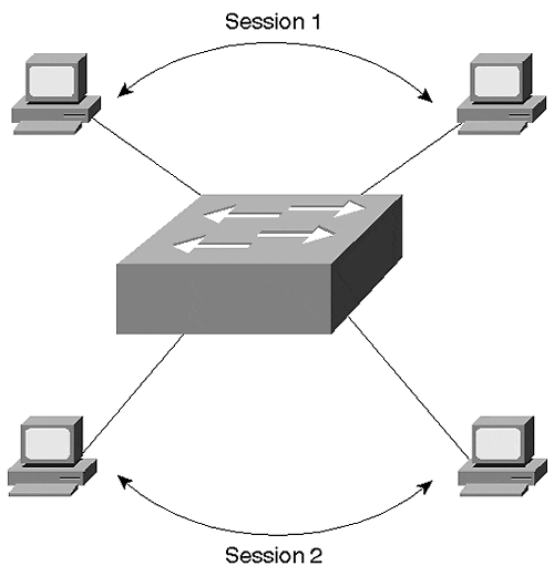
What exactly is a LAN switch? A LAN switch is a multiport bridge that allows workstations to attach directly to the switch to experience full media bandwidth and enables many workstations to transmit concurrently. For example, Figure 2-12 shows four workstations communicating at the same time, something impossible in a shared network environment.
Figure 2-12. Multiple Concurrent Sessions through a LAN Switch

Because a switch is nothing more than a complex bridge with multiple interfaces, all of the ports on a switch belong to one broadcast domain. If Station 1 sends a broadcast frame, all devices attached to the switch receive it. The switch floods broadcast transmissions to all other ports. Unfortunately, this makes the switch no more efficient than a shared media interconnected with repeaters or bridges when dealing with broadcast or multicast frames.
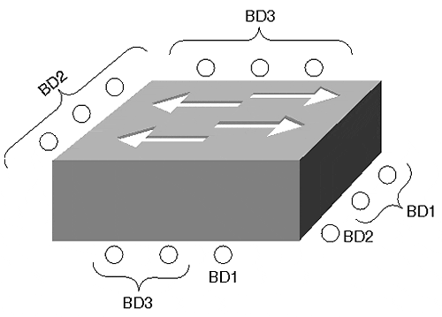
It is possible to design the switch so that ports can belong to different broadcast domains as assigned by a network administrator, thus providing broadcast isolation. In Figure 2-13, some ports belong to Broadcast Domain 1 (BD1), some ports to Broadcast Domain 2 (BD2), and still others to Broadcast Domain 3 (BD3). If a station attached to an interface in BD1 transmits a broadcast frame, the switch forwards the broadcast only to the interfaces belonging to the same domain. The other broadcast domains do not experience any bandwidth consumption resulting from BD1's broadcast. In fact, it is impossible for any frame to cross from one broadcast domain to another without the introduction of another external device, such as a router, to interconnect the domains.
Figure 2-13. A Multibroadcast Domain Capable Switch

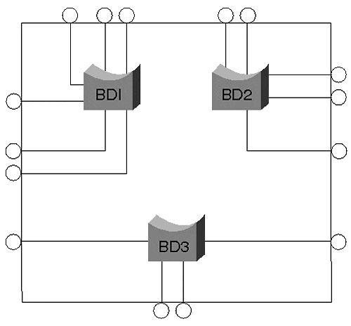
Switches capable of defining multiple broadcast domains actually define virtual LANs (VLANs). Each broadcast domain equates to a VLAN. Chapter 5, "VLANs," discusses VLANs in more detail. For now, think of a VLAN capable switch as a device that creates multiple isolated bridges as shown in Figure 2-14.
Figure 2-14. A Logical Internal Representation of a VLAN Capable Switch

If you create five VLANs, you create five virtual bridge functions within the switch. Each bridge function is logically isolated from the others.
EAN: N/A
Pages: 223