Composing Interaction Diagrams
We discussed the basic parts of a sequence diagram earlier in this chapter: the participating objects and their lifelines, events, and messages. But a problem that occurs with sequence diagrams, as with any sort of scenario-based documentation or diagramming is that they can become complex as well as redundant. The scenario and its corresponding sequence diagram, for a Potential Guest making a successful online reservation is very long, and the scenario for failing to so (because of a rejected credit card) is just as long and mostly the same. If you run into this problem while constructing use cases, simply capture one scenario as the main flow, abstract out the essential differences between the scenarios, and document the differences in an alternate flow,(as described in Chapter 9).
In sequence diagrams, you do almost the same thing. Instead of documenting the essential differences somewhere else, you use the power of graphical representation to display the variations side by side. (Remember, however, that you can suppress details for readability’s sake, and present them later.) In this section, we cover some ways you can use UML to document complex scenarios.
Referencing and reusing interactions
The most common problem with sequence diagrams—or, for that matter, with any interaction diagram—is that you can’t quite avoid redundancy with another sequence diagram: Often two scenarios overlap. The solution here is to make (and document) an interaction occurrence that you can refer to in several other diagrams. The technique is easy and pretty slick: Any named interaction diagram can be referred to by name and inserted into another diagram.
UML2 Earlier in this chapter, we provided a sequence diagram for the scenario of guaranteeing a reservation (shown in Figure 12-3). Suppose that diagram contains an interaction that we want to reuse elsewhere—or from which we want to extract the details for encapsulation. To refer to this interaction, we use what UML 2 calls an interaction occurrence, which is a reference to a reusable piece of an interaction defined elsewhere.
In Figure 12-7, we first define the sequence diagram for Validate Credit Card. Here the interaction is simple, consisting of two objects and two messages, but it could be very complex.
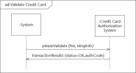
Figure 12-7: An interaction called Validate Credit Card.
In Figure 12-8, we refer to our defined interaction by using a UML frame with the operator in the label box, ref, and the title of the interaction in the body section of the frame. This reference is an occurrence of the interaction Validate Credit Card, hence the name interaction occurrence. You can use a reference like this anywhere in an interaction diagram. In typical use, it just means inserting the referenced behavior into the larger diagram. This approach is a suitable way (especially for use cases) to eliminate redundant diagramming.
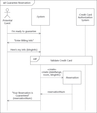
Figure 12-8: Incorporating a reference.
Adding parameters to an interaction
You can use this sort of reference anywhere in an interaction diagram. In the typical use, it just means that there is an insertion of the referenced behavior into the larger diagram. However, you often find that the behavior has some slight differences in each occurrence. You need to be able to tailor the inserted sequence diagram to the current situation.
You can be more explicit about how the inserted behavior works while making it more reusable if you add input and output parameters to the interaction. In Figure 12-9, for example we’ve redefined the inserted sequence diagram to indicate that it needs fee and blngInfo as inputs and that it returns status as a return value and authCode as an out parameter. The syntax for indicating the input and output parameters is the same as shown for operations in Chapter 3.
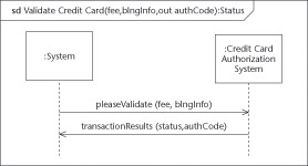
Figure 12-9: Adding arguments to an interaction.
Figure 12-10 shows how these returned values are now used. You indicate where you want to assign the returned values in the reference to the interaction. In the reference to the Validate Credit Card interaction of Figure 12-10, the System.Transaction.Status attribute is assigned the return value from the interaction (the use of the equal sign indicates the assignment), and the System.Transaction.AC is assigned the value of the out parameter authCode. When the Validate Credit Card interaction finishes, both output parameters (the return value status and authCode) are assigned to some attribute of the Transaction object that is part of the System object.
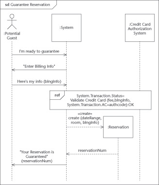
Figure 12-10: Passing and returning arguments from an interaction.
Alternating interactions with combined fragments
One common difficulty occurs when the main path splits into several paths and depends on the return from a message (or some other condition) before it can proceed.
UML2 UML 2 gives you several different operators to use in this situation; you can indicate whether a sequence may be optional (opt), may be repeated (loop), or may have an alternative (alt).
Taking an optional path
You can use a frame with the opt operator to indicate that it may not be used under some circumstances. Usually you place an explicit guard (that is, a test) in square brackets to indicate such a condition.
In the example shown in Figure 12-11, we’ve changed the reference to the interaction occurrence of Validate Credit Card to return a generic Status from the previous example of Figure 12-10, where we set the Status to OK. This is followed by a frame with the opt operator. The whole interaction fragment contained in the frame is optional—and can only occur if the guard [status=OK] is true. You can also put the guard in the label along with the operator opt [status=OK].
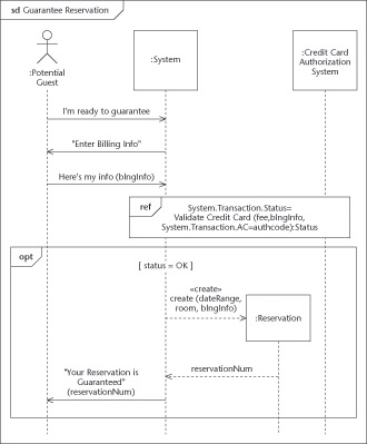
Figure 12-11: An optional interaction.
Looping around a path
In some situations, instead of an interaction occurring zero times or one time, it may be repeatable multiple times. That’s when you use the loop operator, which looks like this:
loop minint, maxint, [guard] You replace minint, maxint, guard with actual values as follows:
-
minint: Must loop at least this number of times.
-
maxint: This parameter is optional. The interaction may not loop more than this number of times. If not given, maxint = minint.
-
guard: A guard is an optional condition shown in square brackets. After the first minint iterations, the condition is tested before each additional loop iteration. If the condition is false, then the loop is abandoned. If the guard is not specified, it is assumed to be true, so the loop continues to iterate until the maxint iterations are performed.
An example of a loop is shown in Figure 12-12. We allow the Potential Guest three tries to find a credit card to be good. By setting the minint to 1, we’re requiring the loop to be executed at least one time. By setting the maxint to 3, we’re requiring the loop to execute no more than three times. The loop exits early if it tries to start the second or third iteration and the guard, [status= bad] is false, which will be the case if the card’s status is good.
Breaking out of a loop
Loops can be sticky, and often you’ll find you need a way of escaping from them. UML supplies the break operator for that purpose; you can use it to indicate the scenario that causes escape from a loop (or from any enclosing segment) and that processing continues with the first message after the loop. In Figure 12-12, we show that if the actor selects the Cancel key/button, the loop is immediately escaped.
Making a decision on the path
If you have two more choices for the path to take, you can set yourself up with the alt operator. Divide your frame into sections with interactions inside each of the sections. Place a guard to control whether the section is entered. You can use [else] as the guard to the last section—it will be entered if none of the above sections are entered (because all the other guards are false).
The alt operator is the construct to use if you’re thinking of including an if or case statement in your code. In the example shown in Figure 12-12, the top section of the alt operator is executed if status=OK. If the status is not OK—say, because the loop executed three times without success or because the actor hit the Cancel key/button—then a warning message is issued instead.
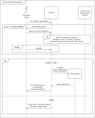
Figure 12-12: Looping and alternatives.
Choosing advanced operators
UML 2 gives you many operators to use if you want to compose complex interaction diagrams. The operators indicate which of several interactions would be executed (such as alt), how many times to execute a particular interaction (loop, opt, break), how to interpret the interaction (assert, neg), and the relationship of the interaction with other ongoing interactions and events (par, region). Table 12-1 shows some of these operators and how you can use them. For the programmers among you, we give some idea of the programming statements that correspond to some of these operators.
| Operator | Keywords | Description |
|---|---|---|
| alt | [guard1] ... | Selects one interaction to execute from a set of interactions. The selected interaction follows a true guard condition or an [else] condition if none of the guard conditions are true. In programming, this corresponds to statements like case or if] ... then ... else ... endif. |
| assert | The selected interaction must occur exactly in the way indicated. If it doesn’t, you have an invalid interaction. | |
| break | If the selected interaction occurs, the enclosing interaction (usually a loop) is abandoned. You may be familiar with this as the programming statements of break or escape. | |
| loop | minint, | Execute the interaction minint times, then execute the interaction up to maxint times as long as the [guard] is true. This corresponds to programming statements such as do ... until, while, or for .... |
| neg | This interaction is invalid and can’t occur. | |
| opt | [guard] | This interaction only occurs if the [guard] is true. This corresponds to the programming statement if...endif . |
| par | This operator indicates several interactions that may run concurrently (overlapped in time). For example, several threads of the interactions Make Room Reservation and Canceling a Reservation may be running in parallel. | |
| ref | Refers to an interaction defined elsewhere. This corresponds to the programming concepts of call or invoke or the use case concept of «include». | |
| region | The enclosed interaction is a critical region. No other messages can interleave. A critical region is needed when a shared resource is updated to prevent the updates from overlapping and producing inconsistent results. You would typically use this within parallel interactions. For example, many threads of the Make Room Reservation may be running in parallel, but a critical region is needed when you seize the room, or else several Potential Guests may wind up reserving the same room. |
EAN: 2147483647
Pages: 193