Diagramming an Interaction Scenario
All interaction diagrams capture at least one interaction, which is the interplay of messages sent between objects over time for a specific purpose. Usually the most important interactions you document are the major use-case scenarios. In this context, we use the term scenario as defined in Chapter 9—an instance of a use case. As discussed in Chapter 9, each use case has a generalized description of its most common scenario—its main course or main flow. In such a flow, you describe the interaction of participating objects as an ordered set of steps or actions that an actor (or system) takes as the flow plays out.
A participating object takes a set of actions, communicating the results of one or more of these actions in a message to another participating object—which (in turn) takes its own set of actions and communicates. Sometimes the participating object needs help from other object, so it requests a service in a message to another participating object, which (in turn) takes its own set of actions and communicates. When you draw an interaction diagram, you emphasize the message sequences among the participating objects, as shown in Figure 12-1, and (usually) hide the internal actions.
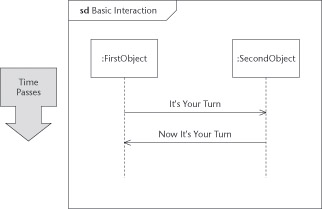
Figure 12-1: A basic sequence diagram.
In the sample diagram in Figure 12-1, you can see the basic features of a sequence diagram. You diagram the participating objects as vertical lifelines. These lifelines consist of an icon indicating the type of participant (such as an object or an actor instance) at the top of a dashed line where you can indicate the messages sent and received by the participating object. Show the messages among the objects as directed arrows from sender to target object. In this diagram, the FirstObject informs the SecondObject that It’s Your Turn, and later, the SecondObject informs the FirstObject that Now It’s Your Turn. The convention is that time passes as you read down the page, though you can turn the diagrams so time runs from left to right. As is typical in these diagrams, the messages alternate.
Place the interaction in the contents area of a frame, and then place the diagram interaction’s title in the odd-shaped heading area (a rectangle with a cut-off corner) in the upper-left corner. The heading contains a prefix that describes the type of interaction you’ve placed in the frame. The sample diagram shows the interaction as a sequence diagram, so the descriptive prefix can be sequence diagram (for which the typical abbreviation is sd).
UML2 The frame and heading, new in UML 2, are applicable to all UML diagrams. Because UML 2 must be backward-compatible with previous work, the frame and heading are optional, and for the most part, you don’t need to use them. However, we recommend using them with interaction and behavioral modeling as they form the basis for behavioral decomposition (as shown later in this chapter).
In Figure 12-2, we’ve diagrammed the main course from the Make Room Reservation use case discussed in Chapter 9 (and added a bit more detail for illustrative purposes). In this diagram, you can see how we used the sequence diagram to extract and show specific instances of communication among interacting entities. You don’t show details of what must be done, just the messages—which makes it easy to see what’s going on. This is an example of how UML uses abstraction to make your work understandable by hiding the details of internal behavior.
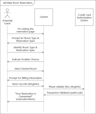
Figure 12-2: A sequence diagram for the Make Room Reservation use case.
Choosing your interaction scenarios during analysis
You probably notice that the basic sequence diagram doesn’t add much more than the textual approach to use cases (discussed in Chapter 9). Of the two techniques—textual use cases and graphical sequence diagrams—textual use cases actually contain more information. Sequence diagrams just extract and show the messages that move among the objects; the use case tells more about what the system has to do—which makes for a fuller picture of the requirements it must meet.
So, if you fully document a simple use case in text (using the techniques of Chapter 9), you probably won’t need to draw additional sequence diagrams to account for every flow. On the other hand, pictures are worth thousands of words—and sequence diagrams are very communicative. Often the quickest way to get a team to understand a scenario is to put a sequence diagram on a whiteboard, extracting the essence of the scenario. This is an application of the principle of abstraction to improve communication.
Our practical advice—for initial analysis, anyway—is that you draw sequence diagrams for only those scenarios that need better explaining or supplemental communication. Drawing up the main course and one other illustrative scenario would suffice for a typical complex use case. (Even that might be too much for some simple use cases.)
Tip If you need to draw other scenarios of a particular use case, abstract out the essences of those scenarios and draw only the differences—that is, capture the alternate flows, not entire alternate scenarios. Try to avoid getting yourself bogged down with redundant diagramming.
Examining object lifelines
Figure 12-2 shows the lifelines of three interacting participants: the actor Potential Guest, the system being built, and another actor—the Credit Card Authorization System. You can have your sequence diagram contain any UML entity that can exhibit behavior. Normally, these will be actors (see Chapters 8 and 9), systems or subsystems (see Chapters 9 and 20), objects (see Chapter 2), parts (see Chapter 5), and components (see Chapter 19). For sequence diagrams done during analysis (that is, before you do the design) that you use to diagram a use-case flow, you will normally be restricted to actors and systems. As you move into design, additional participants (usually objects) will start to appear. These will be the objects added to realize the scenario. At an even lower level, if you use a sequence diagram to diagram an operation’s method, you can show lifelines for parameters and return values. Whatever type of participant you have, place its representative symbol at the top of the diagram and extend its dashed line to the bottom of diagram.
As the messages play across the lifelines, they tell the reader a story of the scenario. In my example, the actor, Potential Guest, visits the appropriate Web page, which notifies the system of his/her presence. The system displays prompts for necessary information, to which the actor responds. This alternates until the actor enters his/her billing information. Then, the system forwards the billing information to the external Credit Card Authorization. As authorization is granted, the system tells the Potential Guest that the reservation is guaranteed and the scenario ends.
Creating and destroying objects
Not every participant exists throughout the entire interaction. Although the external participants may be out of your scope, every internal object you must create somewhere and you must destroy somewhere. Before you finish design, you should find out those wheres for each major internal object. In Figure 12-3, for example, the object Reservation is created in this interaction (as indicated by a dashed line directly into the object’s box), and the lifeline starts down from that point.
You can also indicate that you want to destroy an object in an interaction. In Figure 12-4, we show that the object Reservation is destroyed if the Potential Guest cancels his reservation. You can indicate this graphically by ending the lifeline with a large graphic X. In this diagram, we also show that one can use a selector or qualifier to indicate which specific object is participating. You can do this yourself by putting the selector in the qualifier brackets before the class name of the object.
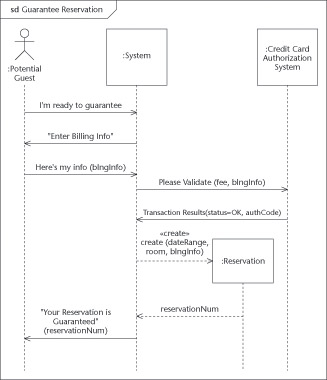
Figure 12-3: Guarantee Reservation and creating an object within the Guarantee Reservation system.
The basic notation for a participating entity’s name includes such parts as qualifier, selector, and class name, ordered as follows:
roleName [qualifier/selector] :ClassName Place the name in the participant’s box (or under it) on top of its dashed line. In Figure 12-4, the rightmost lifeline represents the participating Reservation object. Though we didn’t bother giving it a specific role name (it’s optional), it’s not just any Reservation object that gets destroyed. (We use resNum as the selector to choose the correct Reservation object.) As the figure indicates, the Cancel Reservation interaction requests a reservation number from the Potential Guest and uses the input resNum to identify and delete the correct Reservation.
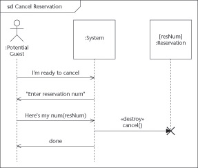
Figure 12-4: Destroying an object in the cancel Reservation system.
You may flag the creating message with the stereotype «create» (as we did in the Figure 12-3) and the destroying message with the stereotype «destroy», (as we did in Figure 12-4), but such redundancies often clutter up diagrams. Use them only if your UML tool requires them for code-generation purposes.
Sending messages
The lives of objects would be very boring if they didn’t get messages from other objects. Each incoming message may stimulate it to calculate a result, to start a behavior, to create another object, or to die. The arrows from lifeline to lifeline indicate one object sending a message to another object to stir up some activity or response.
When you have an object receive a message, it’s a big event in the life of the object. It’s called a ReceiveEvent and it occurs at the tip of the arrowhead where it touches the lifeline. (As you can imagine, the sending of an object is called a SendEvent, but those are less useful.) ReceiveEvents are important because they are the primary way an object gets to change its state. If you go to your state diagrams for the target object, you should find an incoming event for every possible ReceiveEvent and a corresponding state transition (a change of state caused by an incoming event) or internal transition (a response to an event without changing the state). By examining and combining all sequence diagrams that an object of a particular class participates in, you can complete the state diagram for that class. (You can find more about state diagrams, transitions, and using sequence diagrams to construct state diagrams in Chapter 16.)
You use the directed line to show the sending of messages from one object to another. While you do requirements and analysis work, or are early in your project, you’ll probably be using the plain “V” arrow (?) to show messages. (You can see several examples to this type of arrow if you refer to Figure 12-1 through 12-4.) When you use this arrowhead shape, you indicate that the message is sent and received in an unspecified manner, by some undefined signaling technique. That is, the sender may tap the shoulder of the receiver, pass a note, call on the receiver’s telephone, or call on the receiver’s operation. During design or later in the project, you need to be more precise. At that point, the ? arrow indicates asynchronous messages, which we discuss in the section “Going on without an answer (asynchronous call)” later in this chapter.
Naming your messages
When you diagram a message, center the name of the message above the arrow to indicate what the sender wants the receiver to know. You can choose any of several message-naming styles. We generally recommend a naming approach that’s informative or interrogative, but not procedural. (If the message tells the receiver that something happened, it’s informative. If the message tells the receiver that the sender wants something, it’s interrogative. But if the message doesn’t tell the receiver what to do about the situation, then it’s procedural.)
Good examples appear in Figure 12-3, where the Potential Guest tells the System, I’m Ready to Guarantee, and in Figure 12-4 the Potential Guest tells the System, Here’s my num(resNum). The sender tells the receiver that some information is available, and that an event has happened, is happening, or has stopped happening. Grammatically, these message names are declarative and are in the present or past tense. This naming approach is the most flexible because it assumes nothing about the nature of the relationship between sender and receiver. By using it, you support the good practice of decoupling, which entails encouraging flexibility by limiting dependencies between the participants.
Using parameters and arguments with messages
Messages can have parameters or arguments if you want to indicate data or an object being passed along with the message. The syntax for an argument (in a message or an operation) is as follows:
direction argumentName: ArgumentType [Multiplicity] = defaultValue
Remember The direction is either in, out, or inout, indicating whether the argument is input to the message, output from the message, or both. If you don’t specify the direction for argument, it defaults to in.
If there’s a particular argument in the list that you don’t need to specify because it’s not relevant to your flow, you should replace it with a hyphen (-).
Tip Use the defaultValue to show any explicit value that the argument takes in this scenario. By doing this, you make the story explicit and easy to follow. When you need to develop test scripts (later in the process of development), you’ll find it convenient to use these sequence diagrams as a source if they have the values indicated. The following example of this technique also appears in Figure 12-3; here the result from the Credit Card Authorization System is a status of OK:
Transaction Results (status=OK, authCode) Early in your project’s development, avoid getting too formal about your arguments; often the reader of the diagram can infer an argument from the name of a message. We recommend that you use actual message arguments for only the most important information you want the system to pass. Concentrate on the following tasks instead:
-
Keep your use case consistent: There is often information you need to track for use-case purposes. Use high-level argument names and document them as classes in your class diagrams and/or in tables of text in your use-case specifications. By using the arguments in this way, you allow the use case’s reader to track the information flow and check for completeness. Later, you should decompose these arguments into detailed components as they help the user-interface designer to determine what fields need to be included in the interface.
-
Documenting workflow: A common pattern to these sequence diagrams is where the sender passes an object to receiver, who might do some work with it, but then passes it along to another receiver. This is an example of workflow, which might best be documented with a UML activity diagram (described in Chapter 13). However, you’ll often find workflow illustrated in a sequence diagram. When you do, show the passed object as an argument in the messages as they go back and forth among the objects. Figure 12-3, for example, uses the argument blngInfo (short for BillingInfo) to stand for the information that the actor Potential Guest passes to the System, which passes it on to the Credit Card Authorization System.
Remember Don’t forget to consider drawing a state diagram (as discussed in Chapter 16) for the passed object if it changes state as other objects take turns dealing with it. And (of course) document the passed object in an appropriate class diagram.
As you start doing detailed design, replace any informal argument descriptions with complete definitions. Doing so allows your UML tool to check for consistency and automatically generate code.
Quoting a message
Another common approach is to put the message name in quotes when you mean that there is a literal error message or screen message that needs to be displayed. Even if the text is not meant to be the literal message text, using the quotes flags to the reader that a literal message needs to be written or a screen displayed. You might think of the quotes around “Enter Reservation Number” as shorthand for the wordier I’ve Sent To You(msg:String=”A Literal Message”).
Designing a message name
During design and implementation, you should make the message names and their arguments match your intended implementation. If you implement your messages with an operation call (as most messages are), their names and their arguments should match your standard for writing operations. You can still use the informative and interrogative forms (described earlier in this chapter in section “Naming your messages”), but you may find it more useful to use imperative forms to the messages. For example, instead of System, I’m Ready to Guarantee, you’re more likely to use something like System Guarantee My Reservation or System.guaranteeReservation(res : myReservation).
Pressing a button
Tip Another shortcut—used in naming messages and their parameters—you can apply when the argument of the message is a button name. This is the case when an actor sends the message by pushing a real physical button on the hardware (or by clicking a visual button on-screen). For example, instead of naming the message something like
buttonSelected(buttonName : ButtonNameType="Submit") we recommend
selected Submit or submit Selected or the even the simplest: submit.
We use the underline to replace the whole rigmarole of indicating the operation name, argument name and value. Yet it makes the message clearer to the reader and more likely to fit above the very small arrows that volley across typical sequence diagrams. For an example of how this looks in a diagram, you can refer to Figure 12-12 later in this chapter; it uses a cancel to indicate that the actor presses the Cancel button.
Remember Your use-case specifications and their sequence diagrams typically shouldn’t be so detailed that they contain user-interface button or key names. However, as you do more design, this shorthand allows you to be brief but precise in the more design-focused sequence diagrams that capture the details of the user-interface.
Designing messages and their methods
Using the plain, unadorned “V” arrow (?) during analysis indicates that you plan to use an unspecified signaling method to send a specified message. This approach may be acceptable while you’re doing requirements and analysis, but it won’t cut it when you’re trying to implement the system. In-between the analysis and implementation phases, you have the chance to state exactly what you want to happen and how it should be done. This phase is called design.
Calling on a neighbor object
The most common mechanism for sending a message between objects is an operation call that uses standard software techniques. (Examples include a Java method, a C++ member function, and sending a message to a Smalltalk object.) You indicate that you want to use a standard call by using the solid triangular arrowhead (›) pointing in the direction of the call (that is either left or right, as the case might be). In Figures 12-3 and 12-4, we use standard calls to create and cancel the reservation.
Returning from a call on a neighbor
In these standard calls, control of the process transfers from the sender to the receiver. The sender pauses until the receiver finishes and returns. You may want to indicate the return (that is, the result you get) from a standard call as a message as well. Why? Because the return may bring in important values, information, or an object that you need to use. Or the return itself may be the significant event that transfers control. Returns are optional to indicate, but when you do so, you use a dashed V-headed arrow (¨ ???????- -). For example, when the System creates a Reservation object (as in Figure 12-3), it returns the reservationNumber to the System for later use.
In Figure 12-5, we diagram a fragment of an interaction diagram in which an actor selects a hotel from a hotel chain and then prints out the information about the hotel. Because we’ve decided to make this a design-time diagram, we have dropped the actors from the diagram and have replaced them with design-time boundary objects (system components that act as the interface or boundary to the actor) we have chosen as part of our design. This is common step in moving to the details of the design-time modeling. Although actors are important to understand when you’re modeling domains and requirements, they’re usually not under your control when you’re designing, so they’re less important during this phase.
In Figure 12-5, we’ve chosen a common architectural design pattern in which a centralized controller maintains detailed, serialized control of the use case in a tightly scripted Kiosk environment. Here the Controller calls each input boundary device in turn, and waits until it gets a response. Messages such as these—going to the boundary objects from the central controller where the central controller has to wait for a response—are indicated with a solid triangular arrowhead (›). You indicate explicit returns with the ¨??? - - and place the return value on top of the arrow.
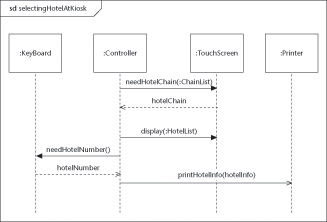
Figure 12-5: Centralized pattern architecture.
You need not always mark the return message explicitly. If the message expression uses the operation form and indicates the return type (or if nothing of interest is returned), you can drop some clutter by dropping the return message. For example, in Figure 12-5, both the needHotelChain(:ChainList) and the display(:HotelList) messages are sent as calls from the Controller to the TouchScreen boundary object. The Controller waits for a reply from the TouchScreen for the selected HotelChain, but does not wait on the TouchScreen for a reply for the display(:HotelList) call, so we decided to skip the explicit return arrow. The Controller does need to know the selected hotel, but we designed that to return via a separate call to the Keyboard.
Going on without an answer (asynchronous call)
Sometimes you don’t want to transfer control—or don’t want to wait at all. You want the sender of the message to keep on going. This situation is called an asynchronous call and it’s where you use the V-shaped arrow (?) during design.
Remember Although the use of asynchronous calls is becoming more common, technically you may use them only if there are multiple threads of control in your system (physically or logically), that is, only if the sender can remain running while the receiver is working. In Figure 12-5, the Controller call to the Printer is an asynchronous call—which is logical because you rarely want to wait until the printer is done before you go on to the next task. Most systems allow spooling of the print job to the printer and concurrent printing and computing.
Signaling by other means
You may find it useful to choose other specific mechanisms for sending a message. Every operating system has several underlying message communications techniques. While they are rare to be used directly for most object-oriented developers, if you need to use them and don’t mind breaking portability you can indicate the mechanism by stereotyping the message with the mechanism, such as «interrupt», «spin-lock», «semaphore». If you use a particular mechanism often, you may want to create a specialized graphic adornment to indicate your mechanism. In Figure 12-6, we list the standard adornments, plus a few common ones we’ve used that are not currently part of the base UML 2 standard.
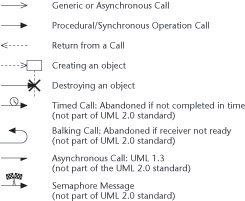
Figure 12-6: Some possible message adornments.
Choosing your interaction scenarios during design
Using interaction diagrams (such as sequence diagrams) during your design activity is very different from using them to gather requirements or assist in analysis. Interaction diagrams can approach the detail and specificity of code. If you are a programmer, you’re likely to be reluctant to be so precise without obvious gain.
There are three primary reasons to consider using sequence diagrams for design:
-
Improved understanding before coding: While you’re likely to be more familiar with coding (and therefore more comfortable with it), UML diagramming—whether with a good-quality tool or a whiteboard—is actually easier to do. It’s worth investing your time to do it well. Once it becomes second nature to you, you’ll find that you can see the general outline of your design in advance—before you even start coding—and you can check it out to make it better, safer, and more complete. To get a visual handle on complicated interactions, you can draw UML interaction diagrams of them before coding them.
-
Improved communication: If you’re a designer responsible for leading several people’s implementations or tests, you’ll find that communicating a design is a lot easier when you use diagrams. The way you want a behavior to work is a lot easier to explain (especially when it involves several objects) if you use UML interaction diagrams. Showing someone a pile of code won’t do much to convey the big picture, nor offer much insight into the way multiple operations work together. Draw UML diagrams to communicate your design for prototypical interactions—and to communicate the sense of how similar interactions are to work.
-
Improved testing and execution: Increasingly the UML tools can test the logic and generate complete code from diagrams such as the interaction diagrams. When using such tools, you won’t need to be thinking as much in a code-specific or language-specific manner unless performance considerations become paramount. Visual modeling and visual testing increasingly eliminate the need for much of the implementation phase—and its associated costs. Of course, reaping that benefit requires near-codelike specificity in the diagrams, but the result is a design that can operate independently of any particular implementation—which saves money and time. If you’re modeling with a tool capable of generating quality code and/or tests, plan on modeling sufficient scenarios to exercise all the logic.
EAN: 2147483647
Pages: 193