Using Project-Oriented Class Diagrams
Class diagrams are also used to pull together key aspects of your project—during analysis, and again during design. Accordingly, it can be helpful to create class diagrams that represent the context of the system, its problem domain, application requirements, and the design of each subsystem.
Establishing contexts
There are two kinds of context diagrams you show with class diagrams:
-
External context diagram: This type of diagram shows a central class and the classes to which it’s related. An external context diagram doesn’t show the internals of the central class but instead illustrates the boundaries of the central class.
-
Internal context diagram: This type of diagram shows the opposite of the external context diagram. You see the internals of a central class but none of the externally related classes.
Use external context diagrams to scope your system (to put a boundary around your system). We use the following steps to se up an external context diagram for our system:
-
Create a class and give it the name of the system you’re developing.
Don’t show any attributes or operations on this class.
-
Think about all the actors and other systems that you expect to interact with your system—and add a class to your diagram for each such interactor.
These are your external classes.
-
Draw an association between each interactor and your system class.
-
Consider the multiplicity of each association.
Ask yourself, How many instances of these actors/systems will my system interact with?
-
Add an operation to any external class if your system must invoke its behavior.
-
Add an attribute to any external class if that class must have some knowledge important to your system.
Internal context diagrams allow you to show internal structure. If you have a complex aggregation, then use this kind of context diagram to show the internal parts of the class. For this diagram, simply inflate the size of the class box. Place a mini-class diagram where you normally show the attributes of the inflated class. Figure 7-8 shows just such an internal context diagram for a generic report. See Chapter 5 for a detailed description for showing the internal parts of a class as a strong form of aggregation. For information about context you show using use case diagrams see Chapter 8.

Figure 7-8: Internal context diagram.
UML2 UML 2 has a new diagram called the composite structure diagram, discussed in Chapter 5. You use composite structure diagrams to show internal context.
Creating domain classes
As you develop your system or software application, you’ll notice that you use some classes over and over again. These highly reusable classes are based on the real world and represent things in your business. In our air-filter example, classes such as Customer, AirFilter, and Coupon are found in the business world. When you talk to users, these are the very words they use when discussing their business. We call these words the domain language or the language of the user. We capture and model this user language for two reasons:
-
Reusability: As a developers, you use domain classes—classes that reflect the domain or language of the user—in several different ways, and each way they are used is known as a use case. (For more on use cases, please read Chapter 8.) For example a manager uses the retail order system to track the sales of air filters to customers and to find out which supplier has the best price for air filters. In both cases different parts of your application software will use instances of the same AirFilter class. These reusable domain classes become the foundation for many of your applications.
-
User verification: Many of the classes in your software represent things in the real world. It’s easier to talk with a user about a problem (and the software you have to build to solve that problem) if your diagram shows classes that are familiar to that user. The user can see the words you have in the diagram and tell you whether it’s right or wrong because you have built a diagram that only includes words from their language—words they are familiar with.
As we mention in the section “Drawing manageable class diagrams,” Figures 7-2, 7-3, 7-4, and 7-5 begin to capture the language of an air-filter order system. Users of that system understand what a coupon is, and they can look at Figure 7-5 and tell you whether you have captured all the different kinds of coupons. These four figures in this chapter are examples of domain diagrams because they describe the domain of ordering air filters in a retail setting. Your classes that capture the language of the user are known as domain classes.
Domain class diagrams that capture the user’s language are good for the following purposes:
-
Defining a common vocabulary between the user and the developer
-
Capturing the most stable classes in your system
-
Staying the same from application to application
-
Removing vagueness from the definition of your real world classes
Tip Develop your domain model during the requirements-gathering phase of your project. Capture in domain class diagrams what the user means as they describe what they do. Refine the domain class diagrams when the user talks about what they want your system to do for them. The very nouns the user says become classes or attributes. The verb phrases from the mouth of the user become associations.
Applying an application perspective
There comes a point in your software development when you want to show which classes come together to bring a use case to life. Remember, object- oriented software contains nothing but objects interacting together. The functionality described in a use case arises from this interaction. You need to show which objects interact to make each use case come to life. To show this relationship, use an application class diagram, which shows which classes work together to perform the job of a use case. The diagram will include a few classes from your domain diagrams as well as special classes known as application classes. Application classes have the attributes and behavior necessary to make your software live up to the description written for a use case.
The following is a list of some application classes that will help you get your project done:
-
Controller class: These are classes that manage the interaction between the user and the internal domain classes in your application. Controllers know when to ask a domain class to make the application work. We usually add a controller class for each use case in our applications. The responsibility of this use case controller class is to ensure that user interactions with the system defined in the use case description are done properly, in the right sequence over time.
-
View class: A view class has the responsibility to manage the user interface boundary between a person and your application. Users want to see the information or objects in your system in a variety of ways. Each view class knows how to interact with the underlying domain classes to show the user a specific view of those domain classes.
-
Boundary class: Boundary classes are similar to view classes because they sit on the boundary between your application and an actor outside your application. Boundary classes interact with other systems, databases, and external devices that interact with your application. For instance, we use boundary classes to separate our application from a database. If any objects within our application require data from a database, they ask a boundary class to go get it for them. That way if the database changes (or the database-access mechanism changes), we only have to change the internal workings of the boundary class. The boundary class hides the complexity of the world outside of my application.
These classes encapsulate the attributes and operations of your application that are “visible” to the user. The controller encapsulates what the user can do and when they can do it for your application. The view classes show things to your users. Boundary classes hide the external interactions of your application from its internal classes.
Figure 7-9 illustrates one of the application class diagrams used in an air-filter order-handling system. The attributes and operations of each class are not shown, making the diagram easier to read. You notice Figure 7-9 actually has two diagrams separated by a thick line. At the top of the figure is a use case diagram showing the review accounts use case. At the bottom of the figure is an application class diagram showing the classes that must perform the Review Accounts use case for the Order Clerk actor. (An actor is a person outside your system that interacts with your system.) The AccountReviewer knows when to access the database via the DatabaseAccessor to retrieve instances of the Customer, CreditCard, and CustomerAccount classes. The Account Reviewer also knows when, at the users request, to create instances of the view classes (CustomerView, CCView, AccountView, and ComplexAccount View) and when to ask a view to show itself to the order clerk user.
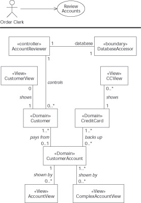
Figure 7-9: Application class diagram.
Notice that we do not draw all the associations between all the classes in Figure 7-9. The AccountReviewer controller class has associations with all the view classes because it must create them, but drawing association all of these lines clutters up the diagram and does not add anything surprising for the developer. Another reason why we may not draw the line between the AccountReviewer class and the other classes is that associations are often reserved for those situations where one class needs to continually know about another class. The more temporary the knowledge of the other class is, the more likely we don’t bother modeling it. When we use a UML modeling tool, we add these extra associations to the diagram just before we ask the modeling tool to generate code.
Remember All you find in object-oriented software is (you guessed it) objects. It’s the objects—not functions—that get together at runtime, collaborate, send messages to each other, and get the job done. Each use case is realized by a group of cooperating objects. Both application objects and domain objects must work together to get a use case to work.
Wrapping packages
At some point in a project, you may find that the modeling you perform to gather requirements, analyze those requirements, and develop software to meet those requirements is getting out of hand. You probably have different levels of class diagrams as well as domain class diagrams and application class diagrams. You might well be wondering how to keep it all under control. We have faced this same problem many times—and each time we used packages. You can wrap up groups of classes and even groups of diagrams into a UML package.
A package is a way of grouping classes together. A UML package looks like a tabbed file folder. You think of the package as containing certain diagrams and/or certain classes. There are several ways of organizing packages for your system:
-
Development phase: Create a package for each development phase—for example, Analysis, System Design, and Detailed Design. Place the classes in each package as you find them during each phase. (Classes discovered during analysis go in the Analysis package.)
-
Diagram type: Create packages to hold the classes and the major types of class diagram. We mention some of those diagrams in this chapter—and we often create Domain, Application, System, and Subsystem packages. We place domain classes and domain class diagrams into the Domain package.
-
Version control: Create packages to represent each version of your system as you develop it. The packages would be named Alpha Version, Beta Version, Release One, and so on. This way all the classes for a particular version are available in one place.
Tip When your development becomes really complex and large, you can put packages inside packages.
To keep track of all those packages, use a package diagram. This diagram simply shows the packages as tabbed folders, with the name of each package on the front of each folder. You can also show any dependencies among your packages by showing a dashed line with an arrow at the end of the line up against the package some other package depends on.
UML2 The package diagram is now an official diagram in UML 2. In previous version of UML we used a class diagram to show packages and their dependencies because there was not official package diagram separate from the class diagram in the UML modeling tool.
Warning Packages own their content. You can’t put the same class into two different packages. Place each class in one—and only one—package. You can use the class in other packages, but some package has to own the reused class, and that’s the only one it should occupy. See Chapter 20 for more details on organizing classes into different packages.
Figure 7-10 is a package diagram showing some of the packages you might have for the retail air-filter order-handling system. The Review Account, Handle Order, and Setup New Clients packages contain classes and diagrams that are specific to use cases by the same name. The Air Filter Domain package just contains other packages. Finally, the Client, Product, and Vendor packages contain groups of classes that are important to each of those major parts of the user’s language.

Figure 7-10: Package diagram.
Dependencies are also shown here. You see a dependency line from the Review Account package to the Air Filter Domain package. The Review Account Package is dependent on the Air Filter Domain package; to review an account, you must also use some of the classes in the Air Filter Domain package.
Remember Packages are a great way to group important stuff together so your complex models don’t get out of hand.
EAN: 2147483647
Pages: 193