5.1 Implement IBM Tivoli Management Framework in an HACMP cluster
|
| < Day Day Up > |
|
5.1 Implement IBM Tivoli Management Framework in an HACMP cluster
IBM Support officially does not recognize implementing two instances of IBM Tivoli Management Framework on a single operating system image. While it is technically possible to implement this configuration, it is not supported. You can read more about this configuration in the IBM Redbook High Availability Scenarios for Tivoli Software, SG24-2032. In this chapter, we show a supported HA configuration for a Tivoli server.
| Important: | Even though both this chapter and 4.1.11, "Add IBM Tivoli Management Framework" on page 303 deal with configuring IBM Tivoli Management Framework for HACMP, they should be treated as separate from each other:
This chapter also provides implementation details for IBM Tivoli Management Framework 4.1. For a discussion on how to implement IBM Tivoli Management Framework 3.7b on the MSCS platform, refer to Appendix B, "TMR clustering for Tivoli Framework 3.7b on MSCS" on page 597. |
We also discuss how to configure Managed Nodes and Endpoints for high availability. The general steps to implement IBM Tivoli Management Framework for HACMP are:
-
"Inventory hardware" on page 413
-
"Planning the high availability design" on page 414
-
"Create the shared disk volume" on page 416
-
"Install IBM Tivoli Management Framework" on page 449
-
"Tivoli Web interfaces" on page 460
-
"Tivoli Managed Node" on page 460
-
"Tivoli Endpoints" on page 462
-
"Configure HACMP" on page 476
The following sections break down each step into the following operations.
5.1.1 Inventory hardware
Here we present an inventory of the hardware we used for writing this redbook. This enables you to determine what changes you may need to make when using this book as a guide in your own deployment by comparing your environment against what we used.
Our environment consisted of two IBM RS/6000 7025-F80s. They are identically configured. There are four PowerPC RS64-III 450 MHz processors in each system. There is 1 GB of RAM in each system. We determined the amount of RAM by using the lsattr command:
lsattr -El mem0
The firmware is at level CL030829, which we verified by using the lscfg command:
lscfg -vp | grep -F .CL
Best practice is to bring your hardware up to the latest firmware and microcode levels. Download the most recent firmware and microcode from:
-
http://www-1.ibm.com/servers/eserver/support/pseries/fixes/hm.html
Onboard the system, the following devices are installed:
-
SCSI 8mm Tape Drive (20000 MB)
-
5 x 16-bit LVD SCSI Disk Drive (9100 MB)
-
16-bit SCSI Multimedia CD-ROM Drive (650 MB)
There are four adapter cards in each system:
-
IBM 10/100 Mbps Ethernet PCI Adapter
-
IBM 10/100/1000 Base-T Ethernet PCI Adapter (14100401)
-
IBM SSA 160 SerialRAID Adapter
-
IBM PCI Token ring Adapter
We did not use the IBM PCI Token ring Adapter.
Shared between the two systems is an IBM 7133 Model 010 Serial Disk System disk tray. Download the most recent SSA drive microcode from:
-
http://www.storage.ibm.com/hardsoft/products/ssa/index.html
The IBM SSA 160 SerialRAID Adapter is listed in this Web site as the Advanced SerialRAID Adapter. In our environment, the adapters are at loadable microcode level 05, ROS level BD00.
There are 16 SSA drives physically installed in the disk tray, but only 8 are active. The SSA drives are 2 GB type DFHCC2B1, at microcode level 8877. In the preceding Web page, the drives are listed as type DFHC (RAMST).
5.1.2 Planning the high availability design
The restriction against two instances of IBM Tivoli Management Framework on the same operating system image prevents mutual takeover implementations. Instead, we show in this section how to install IBM Tivoli Management Framework and configure it in AIX HACMP for a two-node hot standby cluster.
In this configuration, IBM Tivoli Management Framework is active on only one cluster node at a time, but is installed onto a shared volume group available to all cluster nodes. It is configured to always run from the service IP label and corresponding IP address of the cluster node it normally runs upon. Tivoli Desktop sessions connect to this IP address.
In our environment we configured the file system /opt/hativoli on the shared volume group. In normal operation in our environment, the oserv server of IBM Tivoli Management Framework runs on tivaix1 as shown in Figure 5-1 on page 415.
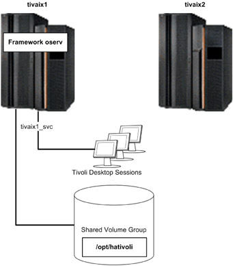
Figure 5-1: IBM Tivoli Management Framework in normal operation on tivaix1
If IBM Tivoli Management Framework on tivaix1 falls over to tivaix2, the IP service label and shared file system are automatically configured by HACMP onto tivaix2. Tivoli Desktop sessions are restarted when the oserv server is shut down, so users of Tivoli Desktop will have to log back in. The fallover scenario is shown in Figure 5-2 on page 416.
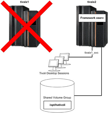
Figure 5-2: State of cluster after IBM Tivoli Management Framework falls over to tivaix2
All managed resources are brought over at the same time because the entire object database is contained in /opt/hativoli. As far as IBM Tivoli Management Framework is concerned, there is no functional difference between running on tivaix1 or tivaix2.
5.1.3 Create the shared disk volume
In this section, we show you how to create and configure a shared disk volume to install IBM Tivoli Management Framework into. Before installing HACMP, we create the shared volume group and install the application servers in them. We can then manually test the fallover of the application server before introducing HACMP.
Plan the shared disk
The cluster needs a shared volume group to host the IBM Tivoli Management Framework upon so that participating cluster nodes can take over and vary on the volume group during a fallover. Here we show how to plan shared volume groups for an HACMP cluster that uses SSA drives.
Start by making an assessment of the SSA configuration on the cluster.
Assess SSA links
Ensure that all SSA links are viable, to rule out any SSA cabling issues before starting other assessments. To assess SSA links:
-
Enter: smit diag.
-
Go to Current Shell Diagnostics and press Enter. The DIAGNOSTIC OPERATING INSTRUCTIONS diagnostics screen displays some navigation instructions.
-
Press Enter. The FUNCTION SELECTION diagnostics screen displays diagnostic functions.
-
Go to Task Selection (Diagnostics, Advanced Diagnostics, Service Aids, etc.) -> SSA Service Aids -> Link Verification and press Enter. The LINK VERIFICATION diagnostics screen displays a list of SSA adapters to test upon. Go to an SSA adapter to test and press Enter.
In our environment, we selected the SSA adapter ssa0 on tivaix1 as shown in Figure 5-3 on page 418.
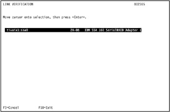
Figure 5-3: Start SSA link verification on tivaix1 -
The link verification test screen displays the results of the test.
The results of the link verification test in our environment are shown in Figure 5-4 on page 419.
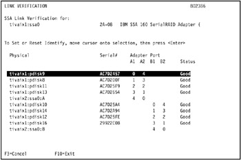
Figure 5-4: Results of link verification test on SSA adapter ssa0 in tivaix1The link verification test indicates only the following SSA disks are available on tivaix1: pdisk9, pdisk8, pdisk11, pdisk13, pdisk10, pdisk14, pdisk14, pdisk12, and pdisk16.
-
Repeat the operation for remaining cluster nodes.
In the environment, we tested the link verification for SSA adapter ssa0 on tivaix2, as shown in Figure 5-5 on page 420.
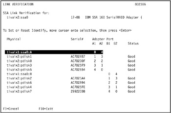
Figure 5-5: Results of SSA link verification test on SSA adapter ssa0 in tivaix2The link verification test indicates only the following SSA disks are available on tivaix2: pdisk0, pdisk1, pdisk2, pdisk3, pdisk4, pdisk5, pdisk6, and pdisk7.
Identify the SSA connection addresses
The connection address uniquely identifies a SSA device. To display the connection address of a physical disk, follow these steps:
-
Enter: smit chgssapdsk. The SSA Physical Disk SMIT selection screen displays a list of known physical SSA disks.
Note You can also enter: smit devices. Then go to SSA Disks -> SSA Physical Disks -> Change/Show Characteristics of an SSA Physical Disk and press Enter.
-
Go to a SSA disk and press Enter, as shown in Figure 5-6 on page 421.
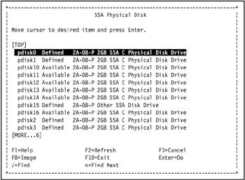
Figure 5-6: Select an SSA disk from the SSA Physical Disk SMIT selection screen -
The Change/Show Characteristics of an SSA Physical Disk SMIT screen displays the characteristics of the selected SSA disk. The Connection address field displays the SSA connection address of the selected disk, as shown in Figure 5-7 on page 422.
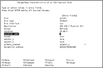
Figure 5-7: Identify the connection address of an SSA disk -
Repeat the operation for all remaining SSA drives.
-
Repeat the operation for all remaining cluster nodes.
An SSA connection address is unique throughout the cluster. Identify the relationship between each connection address and the AIX physical disk definition it represents on each cluster node. This establishes an actual physical relationship between the defined physical disk in AIX and the hardware disk, as identified by its SSA connection address.
In our environment, we identified the SSA connection address of the disks on tivaix1 and tivaix2 as shown in Table 5-1.
| Physical disk on tivaix1 | Connection address | Physical disk on tivaix2 |
|---|---|---|
| pdisk0 | 0004AC7D205400D | pdisk8 |
| pdisk1 | 0004AC7D20A200D | pdisk9 |
| pdisk2 | 0004AC7D22A800D | pdisk10 |
| pdisk3 | 0004AC7D240D00D | pdisk11 |
| pdisk4 | 0004AC7D242500D | pdisk12 |
| pdisk5 | 0004AC7D25BC00D | pdisk13 |
| pdisk6 | 0004AC7D275E00D | pdisk14 |
| pdisk7 | 0004AC7DDACC00D | pdisk15 |
| pdisk8 | 0004AC7D200F00D | pdisk0 |
| pdisk9 | 0004AC7D245700D | pdisk1 |
| pdisk10 | 0004AC7D25A400D | pdisk2 |
| pdisk11 | 0004AC7D25F900D | pdisk3 |
| pdisk12 | 0004AC7D25FE00D | pdisk4 |
| pdisk13 | 0004AC7D265400D | pdisk5 |
| pdisk14 | 0004AC7D2A9400D | pdisk6 |
| pdisk15 | 08005AEA42BC00D | n/a |
| pdisk16 | 000629922C0B00D | pdisk7 |
Using the list of disks identified in the link verification test in the preceding section, we highlight (in bold in Table 5-1 on page 422) the disks on each cluster node that are physically available to be shared on both nodes. From this list we identify which disks are also available to be shared as logical elements by using the assessments in the following sections.
Assess tivaix1
In our environment, the available SSA physical disks on tivaix1 are shown in Example 5-1.
Example 5-1: Available SSA disks on tivaix1 before configuring shared volume groups
[root@tivaix1:/home/root] lsdev -C -c pdisk -s ssar -H name status location description pdisk0 Defined 2A-08-P 2GB SSA C Physical Disk Drive pdisk1 Defined 2A-08-P 2GB SSA C Physical Disk Drive pdisk10 Available 2A-08-P 2GB SSA C Physical Disk Drive pdisk11 Available 2A-08-P 2GB SSA C Physical Disk Drive pdisk12 Available 2A-08-P 2GB SSA C Physical Disk Drive pdisk13 Available 2A-08-P 2GB SSA C Physical Disk Drive pdisk14 Available 2A-08-P 2GB SSA C Physical Disk Drive pdisk15 Defined 2A-08-P Other SSA Disk Drive pdisk16 Available 2A-08-P 2GB SSA C Physical Disk Drive pdisk2 Defined 2A-08-P 2GB SSA C Physical Disk Drive pdisk3 Defined 2A-08-P 2GB SSA C Physical Disk Drive pdisk4 Defined 2A-08-P 2GB SSA C Physical Disk Drive pdisk5 Defined 2A-08-P 2GB SSA C Physical Disk Drive pdisk6 Defined 2A-08-P 2GB SSA C Physical Disk Drive pdisk7 Defined 2A-08-P 2GB SSA C Physical Disk Drive pdisk8 Available 2A-08-P 2GB SSA C Physical Disk Drive pdisk9 Available 2A-08-P 2GB SSA C Physical Disk Drive
The logical disks on tivaix1 are defined as shown in Example 5-2. Note the physical volume ID (PVID) field in the second column, and the volume group assignment field in the third column.
Example 5-2: Logical disks on tivaix1 before configuring shared volume groups
[root@tivaix1:/home/root] lspv hdisk0 0001813fe67712b5 rootvg active hdisk1 0001813f1a43a54d rootvg active hdisk2 0001813f95b1b360 rootvg active hdisk3 0001813fc5966b71 rootvg active hdisk4 0001813fc5c48c43 None hdisk5 0001813fc5c48d8c None hdisk6 000900066116088b tiv_vg1 hdisk7 000000000348a3d6 tiv_vg1 hdisk8 00000000034d224b tiv_vg2 hdisk9 none None hdisk10 none None hdisk11 none None hdisk12 00000000034d7fad tiv_vg2 hdisk13 none None
The logical-to-physical SSA disk relationship of configured SSA drives on tivaix1 is shown in Example 5-3.
Example 5-3: How to show logical to physical SSA disk relationships on tivaix1.
[root@tivaix1:/home/root] for i in $(lsdev -CS1 -t hdisk -sssar -F name) > do > echo "$i: "$(ssaxlate -l $i) > done hdisk10: pdisk12 hdisk11: pdisk13 hdisk12: pdisk14 hdisk13: pdisk16 hdisk6: pdisk8 hdisk7: pdisk9 hdisk8: pdisk10 hdisk9: pdisk11
Assess tivaix2
The same SSA disks in the same SSA loop that are available on tivaix2 are shown in Example 5-4.
Example 5-4: Available SSA disks on tivaix2 before configuring shared volume groups
[root@tivaix2:/home/root] lsdev -C -c pdisk -s ssar -H name status location description pdisk0 Available 17-08-P 2GB SSA C Physical Disk Drive pdisk1 Available 17-08-P 2GB SSA C Physical Disk Drive pdisk10 Defined 17-08-P 2GB SSA C Physical Disk Drive pdisk11 Defined 17-08-P 2GB SSA C Physical Disk Drive pdisk12 Defined 17-08-P 2GB SSA C Physical Disk Drive pdisk13 Defined 17-08-P 2GB SSA C Physical Disk Drive pdisk14 Defined 17-08-P 2GB SSA C Physical Disk Drive pdisk15 Defined 17-08-P 2GB SSA C Physical Disk Drive pdisk2 Available 17-08-P 2GB SSA C Physical Disk Drive pdisk3 Available 17-08-P 2GB SSA C Physical Disk Drive pdisk4 Available 17-08-P 2GB SSA C Physical Disk Drive pdisk5 Available 17-08-P 2GB SSA C Physical Disk Drive pdisk6 Available 17-08-P 2GB SSA C Physical Disk Drive pdisk7 Available 17-08-P 2GB SSA C Physical Disk Drive pdisk8 Defined 17-08-P 2GB SSA C Physical Disk Drive pdisk9 Defined 17-08-P 2GB SSA C Physical Disk Drive
The logical disks on tivaix2 are defined as shown in Example 5-5.
Example 5-5: Logical disks on tivaix2 before configuring shared volume groups
[root@tivaix2:/home/root] lspv hdisk0 0001814f62b2a74b rootvg active hdisk1 none None hdisk2 none None hdisk3 none None hdisk4 none None hdisk5 000900066116088b tiv_vg1 hdisk6 000000000348a3d6 tiv_vg1 hdisk7 00000000034d224b tiv_vg2 hdisk8 0001813f72023fd6 None hdisk9 0001813f72025253 None hdisk10 0001813f71dd8f80 None hdisk11 00000000034d7fad tiv_vg2 hdisk12 0001814f7ce1d08d None hdisk16 0001814fe8d10853 None
The logical-to-physical SSA disk relationship of configured SSA drives on tivaix2 is shown in Example 5-6.
Example 5-6: Show logical-to-physical SSA disk relationships on tivaix2
[root@tivaix2:/home/root] for i in $(lsdev -CS1 -t hdisk -sssar -F name) > do > echo "$i: "$(ssaxlate -l $i) > done hdisk10: pdisk5 hdisk11: pdisk6 hdisk12: pdisk7 hdisk5: pdisk0 hdisk6: pdisk1 hdisk7: pdisk2 hdisk8: pdisk3 hdisk9: pdisk4
Identify the volume group major numbers
Each volume group is assigned a major device number, a unique number on a cluster node different from the major number of any other device on the cluster node. Creating a new shared volume group, on the other hand, requires a new major device number assigned to it with the following characteristics:
-
It is different from any other major number of any device on the cluster node.
-
It is exactly the same as the major number assigned to the same shared volume group on all other cluster nodes that share the volume group.
Satisfy these criteria by identifying the existing volume group major numbers that exist on each cluster node so a unique number can be assigned for the new shared volume group. If any other shared volume groups already exist, also identify the major numbers used for these devices. Whenever possible, try to keep major numbers of similar devices in the same range. This eases the administrative burden of keeping track of the major numbers to assign.
In our environment, we used the following command to identify all major numbers used by all devices on a cluster node:
ls -al /dev/* | awk '{ print $5 }' | awk -F',' '{ print $1 }' | sort | uniq In our environment, the major numbers already assigned include the ones shown in Example 5-7 on page 427. We show only a portion of the output for brevity; the parts we left out are indicated by vertical ellipses (...).
Example 5-7: How to list major numbers already in use on tivaix1
[root@tivaix1:/home/root] ls -al /dev/* | awk '{ print $5 }' | \ > awk -F',' '{ print $1 }' | sort -n | uniq . . . 8 11 . . . 43 44 45 46 47 512 . . . In this environment, the volume groups tiv_vg1 and tiv_vg2 are shared volume groups that already exist. We use the ls command on tivaix1, as shown in Example 5-8,to identify the major numbers used for these shared volume groups.
Example 5-8: Identify the major numbers used for shared volume groups on tivaix1
[root@tivaix1:/home/root] ls -al /dev/tiv_vg1 crw-rw---- 1 root system 45, 0 Nov 05 15:51 /dev/tiv_vg1 [root@tivaix1:/home/root] ls -al /dev/tiv_vg2 crw-r----- 1 root system 46, 0 Nov 10 17:04 /dev/tiv_vg2
Example 5-8 shows that shared volume group tiv_vg1 uses major number 45, and shared volume group tiv_vg2 uses major number 46. We perform the same commands on the other cluster nodes that access the same shared volume groups. In our environment, these commands are entered on tivaix2, as shown in Example 5-9.
Example 5-9: Identify the major numbers used for shared volume groups on tivaix2
[root@tivaix2:/home/root] ls -al /dev/tiv_vg1 crw-r----- 1 root system 45, 0 Dec 15 20:36 /dev/tiv_vg1 [root@tivaix2:/home/root] ls -al /dev/tiv_vg2 crw-r----- 1 root system 46, 0 Dec 15 20:39 /dev/tiv_vg2
Again, you can see that the major numbers are the same on tivaix2 for the same volume groups. Between the list of all major numbers used by all devices, and the major numbers already used by the shared volume groups in our cluster, we choose 49 as the major number to assign to the next shared volume group on all cluster nodes that will access the new shared volume group.
Analyze the assessments
Use the assessment data gathered in the preceding sections to plan the disk sharing design.
Identify which physical disks are not yet assigned to any logical elements. List the physical disks available on each cluster node, as well as each disk's physical volume ID (PVID), its corresponding logical disk, and the volume group the physical disk is assigned to.
If a physical disk is not assigned to any logical elements yet, describe the logical elements as "not available". Disks listed as defined but not available usually indicate connection problems or hardware failure on the disk itself, so do not include these disks in the analysis.
The analysis of tivaix1 indicates that four SSA disks are available as logical elements (highlighted in bold in Table 5-2) because no volume groups are allocated to them: pdisk11, pdisk12, pdisk13, and pdisk16.
| Physical Disk | PVID | Logical Disk | Volume Group |
|---|---|---|---|
| pdisk8 | 000000000348a3d6 | hdisk6 | tiv_vg1 |
| pdisk9 | 000000000348a3d6 | hdisk7 | tiv_vg1 |
| pdisk10 | 00000000034d224b | hdisk8 | tiv_vg2 |
| pdisk11 | n/a | hdisk9 | n/a |
| pdisk12 | n/a | hdisk10 | n/a |
| pdisk13 | n/a | hdisk11 | n/a |
| pdisk14 | 00000000034d7fad | hdisk12 | tiv_vg2 |
| pdisk16 | n/a | hdisk13 | n/a |
We want the two cluster nodes in our environment to share a set of SSA disks, so we have to apply the same analysis of available disks to tivaix2; see Table 5-3 on page 429.
| Physical Disk | PVID | Logical Disk | Volume Group |
|---|---|---|---|
| pdisk0 | 000900066116088b | hdisk5 | tiv_vg1 |
| pdisk1 | 000000000348a3d6 | hdisk6 | tiv_vg1 |
| pdisk2 | 00000000034d224b | hdisk7 | tiv_vg2 |
| pdisk3 | 0001813f72023fd6 | hdisk8 | n/a |
| pdisk4 | 0001813f72025253 | hdisk9 | n/a |
| pdisk5 | 0001813f71dd8f80 | hdisk10 | n/a |
| pdisk6 | 00000000034d7fad | hdisk11 | tiv_vg2 |
| pdisk7 | 0001814f7ce1d08d | hdisk12 | n/a |
The analysis of tivaix2 indicates that four SSA disks are available as logical elements (highlighted in bold in Table 5-3) because no volume groups are allocated to them: pdisk3, pdisk4, pdisk5, and pdisk7.
Pooling together the separate analyses from each cluster node, we arrive at the map shown in Table 5-4. The center two columns show the actual, physical SSA drives as identified by their connection address and the shared volume groups hosted on these drives. The outer two columns show the AIX-assigned physical and logical disks on each cluster node, for each SSA drive.
| tivaix1 disks | Connection address | Volume group | tivaix2 disks | ||
|---|---|---|---|---|---|
| Physical | Logical | Physical | Logical | ||
| pdisk8 | hdisk6 | 0004AC7D200F00D | tiv_vg1 | pdisk0 | hdisk5 |
| pdisk9 | hdisk7 | 0004AC7D245700D | tiv_vg1 | pdisk1 | hdisk6 |
| pdisk10 | hdisk8 | 0004AC7D25A400D | tiv_vg2 | pdisk2 | hdisk7 |
| pdisk11 | hdisk9 | 0004AC7D25F900D | pdisk3 | hdisk8 | |
| pdisk12 | hdisk10 | 0004AC7D25FE00D | pdisk4 | hdisk9 | |
| pdisk13 | hdisk11 | 0004AC7D265400D | pdisk5 | hdisk10 | |
| pdisk14 | hdisk12 | 0004AC7D2A9400D | tiv_vg2 | pdisk6 | hdisk11 |
| pdisk16 | hdisk13 | 000629922C0B00D | pdisk7 | hdisk12 | |
You can think of the AIX physical disk as the handle by which the SSA drivers in AIX use to communicate with the actual SSA hardware drive. Think of the AIX logical disk as the higher level construct that presents a uniform interface to the AIX volume management system. These logical disks are allocated to volume groups, and they map back through a chain (logical disk to physical disk to connection address) to reach the actual SSA hardware drive.
Allocate the SSA disks to a new volume group
The assessments and the analyses shows us that four SSA drives are available to allocate to a volume group for IBM Tivoli Management Framework, and be assigned as a volume group amongst both nodes in our two-node cluster. These are highlighted in bold in the preceding table.
A basic installation of IBM Tivoli Management Framework requires no more than 2 GB. Our assessments in the preceding sections ("Assess tivaix1" on page 423 and , "Assess tivaix2" on page 425) show us that our SSA storage system uses 2 GB drives, so we know the physical capacity of each drive.
We will use two drives for the volume group that will hold IBM Tivoli Management Framework, as shown in the summary analysis table (Table 5-5) that distills all the preceding analysis into the concluding analysis identifying the physical SSA disks to use, and the order in which we specify them when defining them into a volume group.
| tivaix1 Disks | Connection Address | Volume Group | tivaix2 Disks | ||
|---|---|---|---|---|---|
| Physical | Logical | Physical | Logical | ||
| pdisk11 | hdisk9 | 0004AC7D25F900D | itmf_vg | pdisk3 | hdisk8 |
| pdisk12 | hdisk10 | 0004AC7D25FE00D | itmf_vg | pdisk4 | hdisk9 |
The following section describes how to allocate the new volume group on the selected SSA drives.
Configure volume group on SSA drives
Use the SSA drives selected during analysis to configure a volume group upon. This volume group is shared among all the cluster nodes.
To configure a volume group on SSA drives:
-
Select a cluster node from the final analysis table (Table 5-5). Log into that cluster node as root user.
In our environment, we logged into tivaix1 as root user.
-
Enter the SMIT fast path command: smit mkvg. The Add a Volume Group SMIT screen appears.
-
Enter: itmf_vg in the VOLUME GROUP name field.
-
Go to the PHYSICAL VOLUME names field and press F4. The PHYSICAL VOLUME names SMIT dialog appears.
-
Select the physical volumes to include in the new volume group and press Enter. The Add a Volume Group SMIT selection screen appears.
In our environment, we used the summary analysis table to determine that because we are on tivaix1, we need to select hdisk9 and hdisk10 in the Add a Volume Group SMIT selection screen, as shown in Figure 5-8.
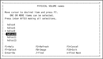
Figure 5-8: Select physical volumes for volume group itmf_vg -
Go to the Volume Group MAJOR NUMBER field and enter a unique major number. This number must be unique in every cluster node that the volume group is shared in. Ensure the volume group is not automatically activated at system restart (HACMP needs to automatically activate it) by setting the Activate volume group AUTOMATICALLY at system restart field to no.
Tip Record the volume group major number and the first physical disk you use for the volume group, for later reference in "Import the volume group into the remaining cluster nodes" on page 444.
In our environment, we entered 49 in the Volume Group MAJOR NUMBER field, and set the Activate volume group AUTOMATICALLY at system restart field to no, as shown in Figure 5-9. We use 49 as determined in "Identify the volume group major numbers" on page 426, so it will not conflict with the major numbers chosen for other volume groups and devices.
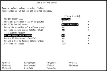
Figure 5-9: Configure settings to add volume group itmf_vg -
Press Enter. The volume group is created.
-
Use the lsvg and lspv commands to verify the new volume group exists, as shown in Example 5-10.
Example 5-10: Verify creation of shared volume group itmf_vg on tivaix1

[root@tivaix1:/home/root] lsvg rootvg tiv_vg1 tiv_vg2 itmf_vg [root@tivaix1:/home/root] lspv hdisk0 0001813fe67712b5 rootvg active hdisk1 0001813f1a43a54d rootvg active hdisk2 0001813f95b1b360 rootvg active hdisk3 0001813fc5966b71 rootvg active hdisk4 0001813fc5c48c43 None hdisk5 0001813fc5c48d8c None hdisk6 000900066116088b tiv_vg1 hdisk7 000000000348a3d6 tiv_vg1 hdisk8 00000000034d224b tiv_vg2 hdisk9 0001813f72023fd6 itmf_vg active hdisk10 0001813f72025253 itmf_vg active hdisk11 0001813f71dd8f80 None hdisk12 00000000034d7fad tiv_vg2 hdisk13 none None
Create the logical volume and Journaled File System
Create a logical volume and a Journaled File System (JFS) on the new volume group. This makes the volume group available to applications running on AIX.
To create a logical volume and Journaled File System on the new volume group:
-
Create the mount point for the logical volume's file system. Do this on all cluster nodes.
In our environment, we used the following command:
mkdir -p /opt/hativoli
-
Enter: smit crjfsstd.
-
The Volume Group Name SMIT selection screen displays a list of volume groups. Go to the new volume group and press Enter. The Add a Standard Journaled File System SMIT screen displays the attributes for a new standard Journaled File System.
In our environment, we selected itmf_vg, as shown in Figure 5-10 on page 434.
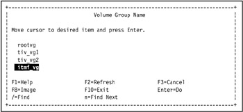
Figure 5-10: Select a volume group using the Volume Group Name SMIT selection screen -
Enter values into the fields.
Number of units
Enter the number of megabytes to allocate for the standard Journaled File System.
MOUNT POINT
The mount point, which is the directory where the file system is available or will be made available.
Mount AUTOMATICALLY at system restart?
Indicates whether the file system is mounted at each system restart. Possible values are:
yes - meaning that the file system is automatically mounted at system restart
no - meaning that the file system is not automatically mounted at system restart.
In our environment, we entered 2048 in the Number of units field, /opt/hativoli in the MOUNT POINT field, and yes in the Mount AUTOMATICALLY at system restart? field, as shown in Figure 5-11 on page 435.
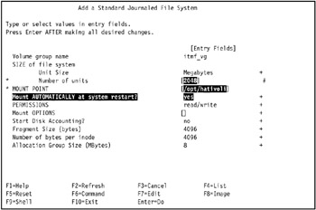
Figure 5-11: Create a standard Journaled File System on volume group itmf_vg in tivaix1 -
Press Enter to create the standard Journaled File System. The COMMAND STATUS SMIT screen displays the progress and result of the operation. A successful operation looks similar to Figure 5-12 on page 436.
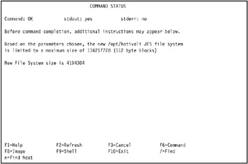
Figure 5-12: Successful creation of JFS file system /opt/hativoli on tivaix1 -
Use the ls, df, mount, and umount commands to verify the new standard Journaled File System, as shown in Example 5-11.
Example 5-11: Verify successful creation of a JFS file system
[root@tivaix1:/home/root] ls /opt/hativoli [root@tivaix1:/home/root] df -k /opt/hativoli Filesystem 1024-blocks Free %Used Iused %Iused Mounted on /dev/hd10opt 262144 68724 74% 3544 6% /opt [root@tivaix1:/home/root] mount /opt/hativoli [root@tivaix1:/home/root] df -k /opt/hativoli Filesystem 1024-blocks Free %Used Iused %Iused Mounted on /dev/lv09 2097152 2031276 4% 17 1% /opt/hativoli [root@tivaix1:/home/root] ls /opt/hativoli lost+found [root@tivaix1:/home/root] umount /opt/hativoli
The new volume group is now populated with a new standard Journaled File System.
| Important: | Our environment does not use multiple SSA adapters due to resource constraints. In a production high availability environment, you use multiple disk controllers. Best practice for HACMP is to use multiple disk controllers and multiple disks for volume groups. Specifically, to ensure disk availability, best practice for each cluster node is to split a volume group between at least two disk controllers and three disks, mirroring across all the disks. |
Configure the logical volume
Rename the new logical volume and its log volume so it is guaranteed to be a unique name in any cluster node. The new name will be the same name on any cluster node that varies on the logical volume's volume group, and must be unique from any other logical volume on all cluster nodes. You only need to perform this operation from one cluster node. The volume group must be online on this cluster node.
In our environment, we wanted to rename logical volume lv09 to itmf_lv, and logical log volume loglv00 to itmf_loglv.
To rename the logical volume and logical log volume:
-
Use the lsvg command as shown in Example 5-12 to identify the logical volumes on the new volume group.
Example 5-12: Identify logical volumes on new volume group
[root@tivaix1:/home/root] lsvg -l itmf_vg itmf_vg: LV NAME TYPE LPs PPs PVs LV STATE MOUNT POINT loglv00 jfslog 1 1 1 closed/syncd N/A lv09 jfs 512 512 1 closed/syncd /opt/hativoli
In our environment, the volume group itmf_vg contains two logical volumes. Logical volume lv09 is for the standard Journal File System /opt/hativoli. Logical volume loglv00 is the log logical volume for lv09.
-
Enter: smit chlv2. You can also enter: smit storage, go to Logical Volume Manager -> Logical Volumes -> Set Characteristic of a Logical Volume -> Rename a Logical Volume and press Enter. The Rename a Logical Volume SMIT screen is displayed.
-
Enter the name of the logical volume to rename in the CURRENT logical volume name field. Enter the new name of the logical volume in the NEW logical volume name field.
In our environment, we entered lv09 in the CURRENT logical volume name field, and itmf_lv in the NEW logical volume name field, as shown in Figure 5-13.
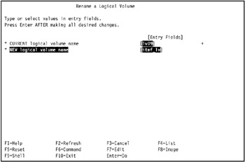
Figure 5-13: Rename a logical volume -
Press Enter to rename the logical volume. The COMMAND STATUS SMIT screen displays the progress and the final status of the renaming operation.
-
Repeat the operation for the logical log volume.
In our environment, we renamed logical volume loglv00 to itmf_loglv, as shown in Figure 5-14 on page 439.
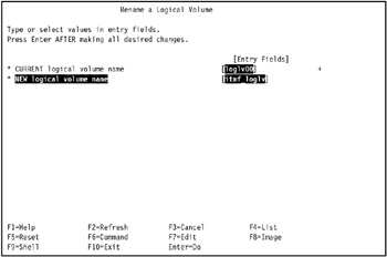
Figure 5-14: REname the logical log volume -
Run the chfs command as shown in Example 5-13 to update the relationship between the logical volume itmf_lv and logical log volume itmf_loglv.
Example 5-13: Update relationship between renamed logical volumes and logical log volumes
[root@tivaix1:/home/root] chfs /opt/hativoli
-
Verify the chfs command modified the /etc/filesystems file entry for the file system.
In our environment, we used the grep command as shown in Example 5-14 on page 440 to verify that the /etc/filesystems entry for /opt/hativoli matches the new names of the logical volume and logical log volume.
Example 5-14: Verify the chfs command
[root@tivaix1:/home/root] grep -p /opt/hativoli /etc/filesystems /opt/hativoli: dev = /dev/itmf_lv vfs = jfs log = /dev/itmf_loglv mount = true check = false options = rw account = false
The attributes dev and log contain the new names itmf_lv and itmf_loglv, respectively.
Export the volume group
Export the volume group from the cluster node it was created upon to make it available to other cluster nodes.
To export a volume group:
-
Log into the cluster node that the volume group was created upon.
In our environment, we logged into tivaix1 as root user.
-
Note that the volume group is varied on as soon as it is created. Vary off the volume group if necessary, so it can be exported.
In our environment, we varied off the volume group itmf_vg by using the following command:
varyoffvg itmf_vg
-
Enter: smit exportvg. The Export a Volume Group SMIT screen displays a VOLUME GROUP name field.
-
Enter the new volume group in the VOLUME GROUP name field.
In our environment, we entered itmf_vg in the VOLUME GROUP name field, as shown in Figure 5-15 on page 441.
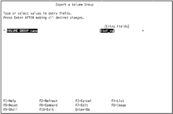
Figure 5-15: Export a Volume Group SMIT screen -
Press Enter to export the volume group. The COMMAND STATUS SMIT screen displays the progress and final result of the export operation.
-
Use the lsvg and lspv commands as shown in Example 5-15 to verify the export of the volume group. Notice that the volume group name does not appear in the output of either command.
Example 5-15: Verify the export of volume group itmf_vg from tivaix1
[root@tivaix1:/home/root] lsvg rootvg tiv_vg1 tiv_vg2 [root@tivaix1:/home/root] lspv hdisk0 0001813fe67712b5 rootvg active hdisk1 0001813f1a43a54d rootvg active hdisk2 0001813f95b1b360 rootvg active hdisk3 0001813fc5966b71 rootvg active hdisk4 0001813fc5c48c43 None hdisk5 0001813fc5c48d8c None hdisk6 000900066116088b tiv_vg1 hdisk7 000000000348a3d6 tiv_vg1 hdisk8 00000000034d224b tiv_vg2 hdisk9 0001813f72023fd6 None hdisk10 0001813f72025253 None hdisk11 0001813f71dd8f80 None hdisk12 00000000034d7fad tiv_vg2 hdisk13 none None
Re-import the volume group
Once we export a volume group, we import it back into the same cluster node we first exported it from. We then log into the other cluster nodes on the same SSA loop as the cluster node we create the volume group upon in "Configure volume group on SSA drives" on page 430, and import the volume group so we can make it a shared volume group.
To import the volume group back to the same cluster node we first exported it from:
-
Log into the cluster node as root user.
In our environment, we logged into tivaix1 as root user.
-
Use the lsvg command as shown in Example 5-16 to verify the volume group is not already imported.
Example 5-16: Verify volume group itmf_vg is not already imported into tivaix1
[root@tivaix1:/home/root] lsvg -l itmf_vg 0516-306 : Unable to find volume group i in the Device Configuration Database.
-
Enter: smit importvg. You can also enter: smit storage, go to Logical Volume Manager -> Volume Groups -> Import a Volume Group, and press Enter. The Import a Volume Group SMIT screen is displayed.
-
Enter the following values. Use the values determined in "Configure volume group on SSA drives" on page 430.
VOLUME GROUP name
The volume group name. The name must be unique system-wide, and can range from 1 to 15 characters.
PHYSICAL VOLUME name
The name of the physical volume. Physical volume names are typically in the form "hdiskx" where x is a system-wide unique number. This name is assigned when the disk is detected for the first time on a system startup or when the system management commands are used at runtime to add a disk to the system.
Volume Group MAJOR NUMBER
The major number of the volume group. The system kernel accesses devices, including volume groups, through a major and minor number combination. To see what major numbers are available on your system, use the SMIT "List" feature.
In our environment, we entered itmf_vg in the VOLUME GROUP name field, hdisk9 in the PHYSICAL VOLUME name field, and 49 in the Volume Group MAJOR NUMBER, as shown in Figure 5-16.
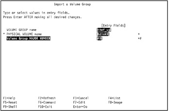
Figure 5-16: Import a volume group -
Press Enter to import the volume group. The COMMAND STATUS SMIT screen displays the progress and final result of the volume group import operation.
-
Vary on the volume group using the varyonvg command.
In our environment, we entered the command:
varyonvg itmf_vg
-
Use the lsvg command as shown in Example 5-17 to verify the volume group import.
Example 5-17: Verify import of volume group itmf_vg into tivaix1
[root@tivaix1:/home/root] lsvg -l itmf_vg itmf_vg: LV NAME TYPE LPs PPs PVs LV STATE MOUNT POINT itmf_loglv jfslog 1 1 1 closed/syncd N/A itmf_lv jfs 512 512 1 closed/syncd /opt/hativoli
-
Vary off the volume group using the varyoffvg command so you can import the volume group into the remaining cluster nodes.
In our environment, we entered the command:
varyoffvg itmf_vg
Import the volume group into the remaining cluster nodes
Import the volume group into the remaining cluster nodes so it becomes a shared volume group.
In our environment, we imported volume group itmf_vg into cluster node tivaix2.
| Note | Importing a volume group also varies it on, so be sure to vary it off first with the varyoffvg command if it is in the ONLINE state on a cluster node. |
To import a volume group defined on SSA drives so it becomes a shared volume group with other cluster nodes:
-
Log into another cluster node as root user.
In our environment, we logged into tivaix2 as root user.
-
Enter the SMIT fast path command: smit importvg. You can also enter: smit storage, go to Logical Volume Manager -> Volume Groups -> Import a Volume Group, and press Enter. The Import a Volume Group SMIT screen is displayed.
-
Use the same volume group name that you used in the preceding operation for the VOLUME GROUP name field.
In our environment, we entered itmf_vg in the VOLUME GROUP name field.
-
Use the summary analysis table created in "Plan the shared disk" on page 417 to determine the logical disk to use. The volume group major number is the same on all cluster nodes, so use the same volume group major number as in the preceding operation.
In our environment, we observed that hdisk9 on tivaix1 corresponds to hdisk8 on tivaix2, so we used hdisk8 in the PHYSICAL VOLUME name field, as shown in Figure 5-17.
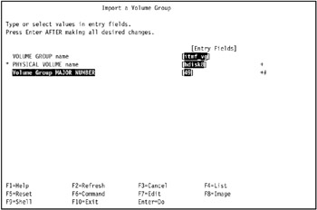
Figure 5-17: Import volume group itmf_vg on tivaix2 -
Press Enter to import the volume group. The COMMAND STATUS SMIT screen displays the progress and final result of the volume group import operation.
-
Use the lsvg and lspv commands to verify the volume group import. The output of these commands contains the name of the imported volume group.
In our environment, we verified the volume group import as shown in Example 5-18 on page 446.
Example 5-18: Verify the import of volume group itmf_vg into tivaix2
[root@tivaix2:/home/root] lsvg rootvg tiv_vg1 tiv_vg2 itmf_vg [root@tivaix2:/home/root] lsvg -l itmf_vg itmf_vg: LV NAME TYPE LPs PPs PVs LV STATE MOUNT POINT itmf_loglv jfslog 1 1 1 closed/syncd N/A itmf_lv jfs 512 512 1 closed/syncd /opt/hativoli [root@tivaix2:/home/root] lspv hdisk0 0001814f62b2a74b rootvg active hdisk1 none None hdisk2 none None hdisk3 none None hdisk4 none None hdisk5 000900066116088b tiv_vg1 hdisk6 000000000348a3d6 tiv_vg1 hdisk7 00000000034d224b tiv_vg2 hdisk8 0001813f72023fd6 itmf_vg active hdisk9 0001813f72025253 itmf_vg active hdisk10 0001813f71dd8f80 None hdisk11 00000000034d7fad tiv_vg2 hdisk12 0001814f7ce1d08d None hdisk16 0001814fe8d10853 None
-
Vary off the volume group using the varyoffvg command.
In our environment, we entered the following command into tivaix2:
varyoffvg itmf_vg
Verify the volume group sharing
Manually verify that all imported volume groups can be shared between cluster nodes before configuring HACMP. If volume group sharing fails under HACMP, manual verification usually allows you to rule out a problem in the configuration of the volume groups, and focus upon the definition of the shared volume groups under HACMP.
To verify volume group sharing:
-
Log into a cluster node as root user.
In our environment, we logged into tivaix1 as root user.
-
Verify the volume group is not already active on the cluster node. Use the lsvg command as shown in Example 5-19 on page 447. The name of the volume group does not appear in the output of the command if the volume group is not active on the cluster node.
Example 5-19: Verify a volume group is not already active on a cluster node
[root@tivaix1:/home/root] lsvg -o rootvg
-
Vary on the volume group using the varyonvg command.
In our environment, we entered the command:
varyonvg itmf_vg
-
Use the lspv and lsvg commands as shown in Example 5-20 to verify the volume group is put into the ONLINE state. The name of the volume group appears in the output of these commands now, where it did not before.
Example 5-20: How to verify volume group itmf_vg is online on tivaix1
[root@tivaix1:/home/root] lsvg -o itmf_vg rootvg [root@tivaix1:/home/root] lsvg -l itmf_vg itmf_vg: LV NAME TYPE LPs PPs PVs LV STATE MOUNT POINT itmf_loglv jfslog 1 1 1 closed/syncd N/A itmf_lv jfs 512 512 1 closed/syncd /opt/hativoli [root@tivaix1:/home/root] lspv hdisk0 0001813fe67712b5 rootvg active hdisk1 0001813f1a43a54d rootvg active hdisk2 0001813f95b1b360 rootvg active hdisk3 0001813fc5966b71 rootvg active hdisk4 0001813fc5c48c43 None hdisk5 0001813fc5c48d8c None hdisk6 000900066116088b tiv_vg1 hdisk7 000000000348a3d6 tiv_vg1 hdisk8 00000000034d224b tiv_vg2 hdisk9 0001813f72023fd6 itmf_vg active hdisk10 0001813f72025253 itmf_vg active hdisk11 0001813f71dd8f80 None hdisk12 00000000034d7fad tiv_vg2 hdisk13 none None
-
Use the df, mount, touch, and ls and umount commands to verify the availability of the logical volume, and to create a test file. The file system and mount point changes after mounting the logical volume.
In our environment, we created the test file /opt/hativoli/node_tivaix1.
Example 5-21: Verify availability of a logical volume in a shared volume group
[root@tivaix1:/home/root] df -k /opt/hativoli Filesystem 1024-blocks Free %Used Iused %Iused Mounted on /dev/hd10opt 262144 68724 74% 3544 6% /opt [root@tivaix1:/home/root] mount /opt/hativoli [root@tivaix1:/home/root] df -k /opt/hativoli Filesystem 1024-blocks Free %Used Iused %Iused Mounted on /dev/itmf_lv 2097152 2031276 4% 17 1% /opt/hativoli [root@tivaix1:/home/root] touch /opt/hativoli/node_tivaix1 [root@tivaix1:/home/root] ls -l /opt/hativoli/node_tivaix* -rw-r--r-- 1 root sys 0 Dec 17 15:25 /opt/hativoli/node_tivaix1 [root@tivaix1:/home/root] umount /opt/hativoli
-
Vary off the volume group using the varyoffvg command.
In our environment, we used the command:
varyoffvg itmf_vg
-
Repeat the operation on all remaining cluster nodes. Ensure test files created on other cluster nodes sharing this volume group exist.
In our environment, we repeated the operation on tivaix2 as shown in Example 5-22.
Example 5-22: Verify shared volume group itmf_vg on tivaix2
[root@tivaix2:/home/root] lsvg -o rootvg [root@tivaix2:/home/root] varyonvg itmf_vg [root@tivaix2:/home/root] lsvg -o itmf_vg rootvg [root@tivaix2:/home/root] lsvg -l itmf_vg itmf_vg: LV NAME TYPE LPs PPs PVs LV STATE MOUNT POINT itmf_loglv jfslog 1 1 1 closed/syncd N/A itmf_lv jfs 512 512 1 closed/syncd /opt/hativoli [root@tivaix2:/home/root] lspv hdisk0 0001814f62b2a74b rootvg active hdisk1 none None hdisk2 none None hdisk3 none None hdisk4 none None hdisk5 000900066116088b tiv_vg1 hdisk6 000000000348a3d6 tiv_vg1 hdisk7 00000000034d224b tiv_vg2 hdisk8 0001813f72023fd6 itmf_vg active hdisk9 0001813f72025253 itmf_vg active hdisk10 0001813f71dd8f80 None hdisk11 00000000034d7fad tiv_vg2 hdisk12 0001814f7ce1d08d None hdisk16 0001814fe8d10853 None [root@tivaix2:/home/root] df -k /opt/hativoli Filesystem 1024-blocks Free %Used Iused %Iused Mounted on /dev/hd10opt 262144 29992 89% 3587 6% /opt [root@tivaix2:/home/root] mount /opt/hativoli [root@tivaix2:/home/root] df -k /opt/hativoli Filesystem 1024-blocks Free %Used Iused %Iused Mounted on /dev/itmf_lv 2097152 2031276 4% 17 1% /opt/hativoli [root@tivaix2:/home/root] touch /opt/hativoli/node_tivaix2 [root@tivaix2:/home/root] ls -l /opt/hativoli/node_tivaix* -rw-r--r-- 1 root sys 0 Dec 17 15:25 /opt/hativoli/node_tivaix1 -rw-r--r-- 1 root sys 0 Dec 17 15:26 /opt/hativoli/node_tivaix2 [root@tivaix2:/home/root] umount /opt/hativoli [root@tivaix2:/home/root] varyoffvg itmf_vg
5.1.4 Install IBM Tivoli Management Framework
In this section we show how to install IBM Tivoli Management Framework Version 4.1 with all available patches as of the time of writing; specifically, how to install on tivaix1 in the environment used for this redbook. We only need to install once, because we used a hot standby configuration. After installing IBM Tivoli Management Framework, we describe how to install and configure HACMP for it on both tivaix1 and tivaix2.
Concurrent access requires application support of the Cluster Lock Manager. IBM Tivoli Management Framework does not support Cluster Lock Manager, so we use shared Logical Volume Manager (LVM) access.
Plan for high availability considerations
We install the IBM Tivoli Management Framework before installing and configuring HACMP—so if IBM Tivoli Management Framework exhibits problems after introducing HACMP, we will know the root cause is likely an HACMP configuration issue.
It helps the overall deployment if we plan around some of the high availability considerations while installing IBM Tivoli Management Framework.
Installation directories
IBM Tivoli Management Framework uses the following directories on a Tivoli server:
-
/etc/Tivoli
-
Tivoli home directory, where IBM Tivoli Management Framework is installed under, and most Tivoli Enterprise products are usually installed in.
| Important: | These are not the only directories used in a Tivoli Enterprise deployment of multiple IBM Tivoli products. |
In our environment, we left /etc/Tivoli on the local drives of each cluster node. This enabled the flexibility to easily use multiple, local Endpoint installations on each cluster node. Putting /etc/Tivoli on the shared disk volume is possible, but it involves adding customized start and stop HACMP scripts that would "shuffle" the contents of /etc/Tivoli depending upon what Endpoints are active on a cluster node.
We use /opt/hativoli as the Tivoli home directory. Following best practice, we first install IBM Tivoli Management Framework into /opt/hativoli, then install and configure HACMP.
| Note | In an actual production deployment, best practice is to implement /etc/Tivoli on a shared volume group because leaving it on the local disk of a system involves synchronizing the contents of highly available Endpoints across cluster nodes. |
Associated IP addresses
Configuring the Tivoli server as a resource group in a hot standby two-node cluster requires that the IP addresses associated with the server remain with the server, regardless of which cluster node it runs upon. The IP address associated with the installation of the Tivoli server should be the service IP address. When the cluster node the Tivoli server is running on falls over, the service IP label falls over to the new cluster node, along with the resource group that contains the Tivoli server.
Plan the installation sequence
Before installing, plan the sequence of the packages you are going to install. Refer to Tivoli Enterprise Installation Guide Version 4.1, GC32-0804, for detailed information about what needs to be installed. Figure 5-18 on page 451 shows the sequence and dependencies of packages we planned for IBM Tivoli Management Framework Version 4.1 for the environment we used for this redbook.
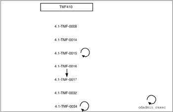
Figure 5-18: IBM Tivoli Framework 4.1.0 application and patch sequence and dependencies as of December 2, 2003
Stage installation media
Complete the procedures listed in "Stage installation media" on page 313 to stage the IBM Tivoli Management Framework installation media.
Modify /etc/hosts and name resolution order
Complete the procedures in "Modify /etc/hosts and name resolution order" on page 250 to configure IP hostname lookups.
Install base Framework
In this section we show you how to install IBM Tivoli Management Framework so that it is specifically configured for IBM Tivoli Workload Scheduler on HACMP. This enables you to transition the instances of IBM Tivoli Management Framework used for IBM Tivoli Workload Scheduler to a mutual takeover environment if that becomes a supported feature in the future. We believe the configuration as shown in this section can be started and stopped directly from HACMP in a mutual takeover configuration.
When installing IBM Tivoli Management Framework on an HACMP cluster node in support of IBM Tivoli Workload Scheduler, use the primary IP hostname as the hostname for IBM Tivoli Management Framework. Add an IP alias later for the service IP label. When this configuration is used with the multiple Connector object configuration described in section, this enables Job Scheduling Console users to connect through any instance of IBM Tivoli Management Framework, no matter which cluster nodes fall over.
IBM Tivoli Management Framework itself consists of a base install, and various components. You must first prepare for the base install by performing the commands as shown in Example 5-23 for cluster node tivaix1 in our environment. On tivaix2, we replace the IP hostname in the first command from tivaix1_svc to tivaix2_svc.
Example 5-23: Preparing for installation of IBM Tivoli Management Framework 4.1
[root@tivaix1:/home/root] HOST=tivaix1_svc [root@tivaix1:/home/root] echo $HOST > /etc/wlocalhost [root@tivaix1:/home/root] WLOCALHOST=$HOST [root@tivaix1:/home/root] export WLOCALHOST [root@tivaix1:/home/root] mkdir /opt/hativoli/install_dir [root@tivaix1:/home/root] cd /opt/hativoli/install_dir [root@tivaix1:/opt/hativoli/install_dir] /bin/sh \ > /usr/sys/inst.images/tivoli/fra/FRA410_1of2/WPREINST.SH to install, type ./wserver -c /usr/sys/inst.images/tivoli/fra/FRA410_1of2 [root@tivaix1:/opt/hativoli/install_dir] DOGUI=no [root@tivaix1:/opt/hativoli/install_dir] export DOGUI
After you prepare for the base install, perform the initial installation of IBM Tivoli Management Framework by running the command shown in Example 5-24. You will see output similar to this example; depending upon the speed of your server, it will take 5 to 15 minutes to complete.
Example 5-24: Initial installation of IBM Tivoli Management Framework Version 4.1
[root@tivaix1:/home/root] cd /usr/local/Tivoli/install_dir [root@tivaix1:/usr/local/Tivoli/install_dir] sh ./wserver -y \ -c /usr/sys/inst.images/tivoli/fra/FRA410_1of2 \ -a tivaix1_svc -d \ BIN=/opt/hativoli/bin! \ LIB=/opt/hativoli/lib! \ ALIDB=/opt/hativoli/spool! \ MAN=/opt/hativoli/man! \ APPD=/usr/lib/lvm/X11/es/app-defaults! \ CAT=/opt/hativoli/msg_cat! \ LK=1FN5B4MBXBW4GNJ8QQQ62WPV0RH999P99P77D \ RN=tivaix1_svc-region \ AutoStart=1 SetPort=1 CreatePaths=1 @ForceBind@=yes @EL@=None Using command line style installation..... Unless you cancel, the following operations will be executed: need to copy the CAT (generic) to: tivaix1_svc:/opt/hativoli/msg_cat need to copy the CSBIN (generic) to: tivaix1_svc:/opt/hativoli/bin/generic need to copy the APPD (generic) to: tivaix1_svc:/usr/lib/lvm/X11/es/app-defaults need to copy the GBIN (generic) to: tivaix1_svc:/opt/hativoli/bin/generic_unix need to copy the BUN (generic) to: tivaix1_svc:/opt/hativoli/bin/client_bundle need to copy the SBIN (generic) to: tivaix1_svc:/opt/hativoli/bin/generic need to copy the LCFNEW (generic) to: tivaix1_svc:/opt/hativoli/bin/lcf_bundle.40 need to copy the LCFTOOLS (generic) to: tivaix1_svc:/opt/hativoli/bin/lcf_bundle.40/bin need to copy the LCF (generic) to: tivaix1_svc:/opt/hativoli/bin/lcf_bundle need to copy the LIB (aix4-r1) to: tivaix1_svc:/opt/hativoli/lib/aix4-r1 need to copy the BIN (aix4-r1) to: tivaix1_svc:/opt/hativoli/bin/aix4-r1 need to copy the ALIDB (aix4-r1) to: tivaix1_svc:/opt/hativoli/spool/tivaix1.db need to copy the MAN (aix4-r1) to: tivaix1_svc:/opt/hativoli/man/aix4-r1 need to copy the CONTRIB (aix4-r1) to: tivaix1_svc:/opt/hativoli/bin/aix4-r1/contrib need to copy the LIB371 (aix4-r1) to: tivaix1_svc:/opt/hativoli/lib/aix4-r1 need to copy the LIB365 (aix4-r1) to: tivaix1_svc:/opt/hativoli/lib/aix4-r1 Executing queued operation(s) Distributing machine independent Message Catalogs --> tivaix1_svc ..... Completed. Distributing machine independent generic Codeset Tables --> tivaix1_svc .... Completed. Distributing architecture specific Libraries --> tivaix1_svc ...... Completed. Distributing architecture specific Binaries --> tivaix1_svc ............. Completed. Distributing architecture specific Server Database --> tivaix1_svc .......................................... Completed. Distributing architecture specific Man Pages --> tivaix1_svc ..... Completed. Distributing machine independent X11 Resource Files --> tivaix1_svc ... Completed. Distributing machine independent Generic Binaries --> tivaix1_svc ... Completed. Distributing machine independent Client Installation Bundle --> tivaix1_svc ... Completed. Distributing machine independent generic HTML/Java files --> tivaix1_svc ... Completed. Distributing architecture specific Public Domain Contrib --> tivaix1_svc ... Completed. Distributing machine independent LCF Images (new version) --> tivaix1_svc ............. Completed. Distributing machine independent LCF Tools --> tivaix1_svc ....... Completed. Distributing machine independent 36x Endpoint Images --> tivaix1_svc ............ Completed. Distributing architecture specific 371_Libraries --> tivaix1_svc .... Completed. Distributing architecture specific 365_Libraries --> tivaix1_svc .... Completed. Registering installation information...Finished.
On tivaix2 in our environment, we run the same command except we change the third line of the command from tivaix1_svc to tivaix2_svc.
Load Tivoli environment variables in .profile files
The Tivoli environment variables contain pointers to important directories that IBM Tivoli Management Framework uses for many commands. Loading the variables in the .profile file of a user account ensures that these environment variables are always available immediately after logging into the user account.
Use the commands in Example 5-25 to modify the .profile files of the root user account on all cluster nodes to source in all Tivoli environment variables for IBM Tivoli Management Framework.
Example 5-25: Load Tivoli environment variables on tivaix1
PATH=${PATH}:${HOME}/bin if [ -f /etc/Tivoli/setup_env.sh ] ; then . /etc/Tivoli/setup_env.sh fi Also enter these commands on the command line, or log out and log back in to activate the environment variables for the following sections.
Install Framework components and patches
After the base install is complete, you can install all remaining Framework components and patches by running the script shown in Example 5-26. If you use this script on tivaix2, change the line that starts with the string "HOST=" so that tivaix1 is replaced with tivaix2.
Example 5-26: Script for installing IBM Tivoli Management Framework Version 4.1 with patches
#!/bin/ksh if [ -d /etc/Tivoli ] ; then . /etc/Tivoli/setup_env.sh fi reexec_oserv() { echo "Reexecing object dispatchers..." if [ `odadmin odlist list_od | wc -l` -gt 1 ] ; then # # Determine if necessary to shut down any clients tmr_hosts=`odadmin odlist list_od | head -1 | cut -c 36-` client_list=`odadmin odlist list_od | grep -v ${tmr_hosts}$` if [ "${client_list}" = "" ] ; then echo "No clients to shut down, skipping shut down of clients..." else echo "Shutting down clients..." odadmin shutdown clients echo "Waiting for all clients to shut down..." sleep 30 fi fi odadmin reexec 1 sleep 30 odadmin start clients } HOST="tivaix1_svc" winstall -c /usr/sys/inst.images/tivoli/fra/FRA410_2of2/JAVA -y -i JRE130 $HOST winstall -c /usr/sys/inst.images/tivoli/fra/FRA410_2of2/JAVA -y -i JHELP41 $HOST winstall -c /usr/sys/inst.images/tivoli/fra/FRA410_2of2/JAVA -y -i JCF41 $HOST winstall -c /usr/sys/inst.images/tivoli/fra/FRA410_2of2/JAVA -y -i JRIM41 $HOST winstall -c /usr/sys/inst.images/tivoli/fra/FRA410_2of2/JAVA -y -i MDIST2GU $HOST winstall -c /usr/sys/inst.images/tivoli/fra/FRA410_2of2/JAVA -y -i SISDEPOT $HOST winstall -c /usr/sys/inst.images/tivoli/fra/FRA410_2of2/JAVA -y -i SISCLNT $HOST winstall -c /usr/sys/inst.images/tivoli/fra/FRA410_1of2 -y -i ADE $HOST winstall -c /usr/sys/inst.images/tivoli/fra/FRA410_1of2 -y -i AEF $HOST wpatch -c /usr/sys/inst.images/tivoli/fra/41TMF008 -y -i 41TMF008 $HOST wpatch -c /usr/sys/inst.images/tivoli/fra/41TMF014 -y -i 41TMF014 $HOST wpatch -c /usr/sys/inst.images/tivoli/fra/41TMF015 -y -i 41TMF015 $HOST reexec_oserv wpatch -c /usr/sys/inst.images/tivoli/fra/41TMF016 -y -i 41TMF016 $HOST wpatch -c /usr/sys/inst.images/tivoli/fra/41TMF017 -y -i TMA2928 $HOST wpatch -c /usr/sys/inst.images/tivoli/fra/41TMF017 -y -i TMA2929 $HOST wpatch -c /usr/sys/inst.images/tivoli/fra/41TMF017 -y -i TMA2931 $HOST wpatch -c /usr/sys/inst.images/tivoli/fra/41TMF017 -y -i TMA2932 $HOST wpatch -c /usr/sys/inst.images/tivoli/fra/41TMF017 -y -i TMA2962 $HOST wpatch -c /usr/sys/inst.images/tivoli/fra/41TMF017 -y -i TMA2980 $HOST wpatch -c /usr/sys/inst.images/tivoli/fra/41TMF017 -y -i TMA2984 $HOST wpatch -c /usr/sys/inst.images/tivoli/fra/41TMF017 -y -i TMA2986 $HOST wpatch -c /usr/sys/inst.images/tivoli/fra/41TMF017 -y -i TMA2987 $HOST wpatch -c /usr/sys/inst.images/tivoli/fra/41TMF017 -y -i TMA2989 $HOST wpatch -c /usr/sys/inst.images/tivoli/fra/41TMF034 -y -i 41TMF034 $HOST reexec_oserv wpatch -c /usr/sys/inst.images/tivoli/fra/41TMF032 -y -i JRE130_0 $HOST This completes the installation of IBM Tivoli Management Framework Version 4.1. The successful completion of the installation performs a gross level verification of IBM Tivoli Management Framework.
After installing IBM Tivoli Management Framework, configure it to meet the requirements of integrating with IBM Tivoli Workload Scheduler over HACMP.
Add IP alias to oserv
Installing IBM Tivoli Management Framework using the service IP hostname of the server binds the Framework server (also called oserv) to the corresponding service IP address.
It only listens for Framework network traffic on this IP address. This ensures a highly available IBM Tivoli Management Framework only starts after HACMP is running.
In our environment, we also need oserv to listen on the persistent IP address. The persistent IP label/address is not moved between cluster nodes when a resource group is moved, but remains on the cluster node to ease administrative access (that is why it is called the persistent IP label/address). Job Scheduling Console users depend upon using the service IP address to access IBM Tivoli Workload Scheduler services.
As a security precaution, IBM Tivoli Management Framework only listens on the IP address it is initially installed against unless the feature specifically disabled to bind against other addresses. We show you how to disable this feature in this section.
To add the service IP label as a Framework oserv IP alias:
-
Log in as root user on a cluster node.
In our environment, we logged in as root user on cluster node tivaix1.
-
Use the odadmin command as shown in Example 5-27 to verify the current IP aliases of the oserv, add the service IP label as an IP alias to the oserv, and then verify that the service IP label is added to the oserv as an IP alias.
Example 5-27: Add IP alias to Framework oserv server
[root@tivaix1:/home/root] odadmin odlist Region Disp Flags Port IPaddr Hostname(s) 1369588498 1 ct- 94 9.3.4.3 tivaix1_svc [root@tivaix1:/home/root] odadmin odlist add_ip_alias 1 tivaix1 [root@tivaix1:/home/root] odadmin odlist Region Disp Flags Port IPaddr Hostname(s) 1369588498 1 ct- 94 9.3.4.3 tivaix1_svc 9.3.4.194 tivaix1,tivaix1.itsc.austin.ibm.com
Note that the numeral 1 in the odadmin odlist add_ip_alias command should be replaced by the dispatcher number of your Framework installation.
The dispatcher number is displayed in the second column of the odadmin odlist command, on the same line as the primary IP hostname of your Framework installation. In Example 5-28, the dispatcher number is 7.
Example 5-28: Identify dispatcher number of Framework installation
[root@tivaix1:/home/root] odadmin odlist Region Disp Flags Port IPaddr Hostname(s) 1369588498 7 ct- 94 9.3.4.3 tivaix1_svc
The dispatcher number will be something other than 1 if you delete and re-install Managed Nodes, or if your Framework server is part of an overall Tivoli Enterprise installation.
-
Use the odadmin command as shown in Example 5-29 to verify that IBM Tivoli Management Framework currently binds against the primary IP hostname, then disable the feature, and then verify that it is disabled.
Example 5-29: Disable set_force_bind object dispatcher option
[root@tivaix1:/home/root] odadmin | grep Force Force socket bind to a single address = TRUE [root@tivaix1:/home/root] odadmin set_force_bind FALSE 1 [root@tivaix1:/home/root] odadmin | grep Force Force socket bind to a single address = FALSE
Note that the numeral 1 in the odadmin set_force_bind command should be replaced by the dispatcher number of your Framework installation.
The dispatcher number is displayed in the second column of the odadmin odlist command, on the same line as the primary IP hostname of your Framework installation. In Example 5-30, the dispatcher number is 7.
Example 5-30: Identify dispatcher number of Framework installation
[root@tivaix1:/home/root] odadmin odlist Region Disp Flags Port IPaddr Hostname(s) 1369588498 7 ct- 94 9.3.4.3 tivaix1_svc
The dispatcher number will be something other than 1 if you delete and re-install Managed Nodes, or if your Framework server is part of an overall Tivoli Enterprise installation.
Important: Disabling the set_force_bind variable can cause unintended side effects for installations of IBM Tivoli Management Framework that also run other IBM Tivoli server products, such as IBM Tivoli Monitoring and IBM Tivoli Configuration Manager. Consult your IBM service provider for advice on how to address this potential conflict if you plan on deploying other IBM Tivoli server products on top of the instance of IBM Tivoli Management Framework that you use for IBM Tivoli Workload Scheduler.
Best practice is to dedicate an instance of IBM Tivoli Management Framework for IBM Tivoli Workload Scheduler, typically on the Master Domain Manager, and not to install other IBM Tivoli server products into it. This simplifies these administrative concerns and does not affect the functionality of a Tivoli Enterprise environment.
-
Repeat the operation on all remaining cluster nodes.
For our environment, we repeat the operation on tivaix2, replacing tivaix1 with tivaix2 in the commands.
Move the .tivoli directory
The default installation of IBM Tivoli Management Framework on a UNIX system creates the /tmp/.tivoli directory. This directory contains files that are required by the object dispatcher process. In a high availability implementation, the directory needs to move with the resource group that contains IBM Tivoli Management Framework. This means we need to move the directory into the shared volume group's file system. In our environment, we moved the directory to /opt/hativoli/tmp/.tivoli.
To use a different directory, you must set an environment variable in both the object dispatcher and the shell. After installing IBM Tivoli Management Framework, perform the following steps to set the necessary environment variables:
-
Create a directory. This directory must have at least public read and write permissions. However, define full permissions and set the sticky bit to ensure that users cannot modify files that they do not own.
In our environment, we ran the commands shown in Example 5-31.
Example 5-31: Create the new .tivoli directory
mkdir -p /opt/hativoli/tmp/.tivoli chmod ugo=rwx /opt/hativoli/tmp/.tivoli chmod u+s /opt/hativoli/tmp/.tivoli
-
Set the environment variable in the object dispatcher:
-
Enter the following command:
odadmin environ get > envfile
-
Add the following line to the envfile file and save it:
TIVOLI_COMM_DIR=new_directory_name
-
Enter the following command:
odadmin environ set < envfile
-
-
Edit the Tivoli-provided set_env.csh, setup_env.sh, and oserv.rc files in the /etc/Tivoli directory to set the TIVOLI_COMM_DIR variable.
-
For HP-UX and Solaris systems, add the following line to the file that starts the object dispatcher:
TIVOLI_COMM_DIR=new_directory_name
Insert the line near where the other environment variables are set, in a location that runs before the object dispatcher is started. The following list contains the file that needs to be changed on each operating system:
-
For HP-UX operating systems: /sbin/init.d/Tivoli
-
For Solaris operating systems: /etc/rc3.d/S99Tivoli
-
-
Shut down the object dispatcher by entering the following command:
odadmin shutdown all
-
Restart the object dispatcher by entering the following command:
odadmin reexec all
5.1.5 Tivoli Web interfaces
IBM Tivoli Management Framework provides access to Web-enabled Tivoli Enterprise applications from a browser. When a browser sends an HTTP request to the Tivoli server, the request is redirected to a Web server. IBM Tivoli Management Framework provides this Web access by using some servlets and support files that are installed on the Web server. The servlets establish a secure connection between the Web server and the Tivoli server. The servlets and support files are called the Tivoli Web interfaces.
IBM Tivoli Management Framework provides a built-in Web server called the spider HTTP service. It is not as robust or secure as a third-party Web server, so if you plan on deploying a Tivoli Enterprise product that requires Web access, consult your IBM service provider for advice about selecting a more appropriate Web server.
IBM Tivoli Management Framework supports any Web server that implements the Servlet 2.2 specifications, but the following Web servers are specifically certified for use with IBM Tivoli Management Framework:
-
IBM WebSphere Application Server, Advanced Single Server Edition
-
IBM WebSphere Application Server, Enterprise Edition
-
IBM WebSphere Enterprise Application Server
-
Jakarta Tomcat
The Web server can be hosted on any computer system. If you deploy a Web server on a cluster node, you will likely want to make it highly available. In this redbook we focus upon high availability for IBM Tivoli Workload Scheduler and IBM Tivoli Management Framework. Refer to IBM WebSphere V5.0 Performance, Scalability, and High Availability: WebSphere Handbook Series, SG24-6198-00, for details on configuring WebSphere Application Server for high availability. Consult your IBM service provider for more details on configuring other Web servers for high availability.
5.1.6 Tivoli Managed Node
Managed Nodes are no different from IBM Tivoli Management Framework Tivoli servers in terms of high availability design. They operate under the same constraint of only one instance per operating system instance. While the AutoStart install variable of the wclient command implies we can configure multiple instances of the object dispatcher on a single operating system instance, IBM Tivoli Support staff confirmed for us that this is not a supported configuration at the time of writing.
Use the wclient command to install a Managed Node in a highly available cluster, as shown in Example 5-32.
Example 5-32: Install a Managed Node
wclient -c /usr/sys/inst.images/tivoli/fra/FRA410_1of2 \ -p ibm.tiv.pr -P @AutoStart@=0 @ForceBind@=yes \ BIN=/opt/hativoli/bin! \ LIB=/opt/hativoli/lib! \ DB=/opt/hativoli/spool! \ MAN=/opt/hativoli/man! \ APPD=/usr/lib/lvm/X11/es/app-defaults! \ CAT=/opt/hativoli/msg_cat! \ tivaix3_svc
In this example, we installed a Managed Node named tivaix3_svc on a system with the IP hostname tivaix3_svc (the service IP label of the cluster node) from the CD image we copied to the local drive in "Stage installation media" on page 451, into the directory /opt/hativoli. We also placed the managed resource object in the ibm.tiv.pr policy region. See about how to use the wclient command.
Except for the difference in the initial installation (using the wclient command instead of the wserver command), planning and implementing a highly available Managed Node is the same as for a Tivoli server, as described in the preceding sections.
If the constraint is lifted in future versions of IBM Tivoli Management Framework, or if you still want to install multiple instances of the object dispatcher on a single instance of an operating system, configure each instance with a different directory.
To configure a different directory, change the BIN, LIB, DB, MAN, CAT and (optionally) APPD install variables that are passed to the wclient command. Configure the Tivoli environment files and the oserv.rc executable in /etc/Tivoli to accommodate the multiple installations. Modify external dependencies upon /etc/Tivoli where appropriate. We recommend using multiple, separate directories, one for each instance of IBM Tivoli Management Framework. Consult your IBM service provider for assistance with configuring this design.
5.1.7 Tivoli Endpoints
Endpoints offer more options for high availability designs. When designing a highly available Tivoli Enterprise deployment, best practice is to keep the number of Managed Nodes as low as possible, and to use Endpoints as much as possible. In some cases (such as, for very old versions of Plus Modules) this might not be feasible, but the benefits of using Endpoints can often justify the cost of refactoring these older products into an Endpoint form.
Unlike Managed Nodes, multiple Endpoints on a single instance of an operating system are supported. This opens up many possibilities for high availability design. One design is to create an Endpoint to associate with a highly available resource group on a shared volume group, as shown in Figure 5-19.
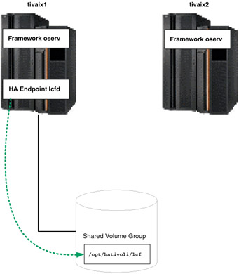
Figure 5-19: Normal operation of highly available Endpoint
Under normal operation, cluster node tivaix1 runs the highly available Endpoint from the directory /opt/hativoli/lcf on the shared volume group. When the resource group falls over, tivaix1 is unavailable and the resource group moves to tivaix2. The Endpoint continues to listen on the IP service address of tivaix1, but runs off tivaix2 instead, as shown in Figure 5-20.
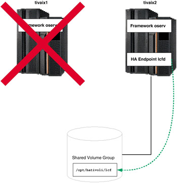
Figure 5-20: Fallover operation of highly available Endpoint
We recommend that you use this configuration to manage HACMP resource group-specific system resources. Examples of complementary IBM Tivoli products that leverage Endpoints in a highly available environment include:
-
Monitor a file system in a resource group with IBM Tivoli Monitoring.
-
Monitor a highly available database in a resource group with IBM Tivoli Monitoring for Databases.
-
Inventory and distribute software used in a resource group with IBM Tivoli Configuration Manager.
-
Enforce software license compliance of applications in a resource group with IBM Tivoli License Manager.
Specific IBM Tivoli products may have specific requirements that affect high availability planning and implementation. Consult your IBM service provider for assistance with planning and implementing other IBM Tivoli products on top of a highly available Endpoint.
Another possible design builds on top of a single highly available Endpoint. The highly available Endpoint is sufficient for managing the highly available resource group, but is limited in its ability to manage the cluster hardware. A local instance of an Endpoint can be installed to specifically manage compute resources associated with each cluster node.
For example, assume we use a cluster configured with a resource group for a highly available instance of IBM WebSphere Application Server. The environment uses IBM Tivoli Monitoring for Web Infrastructure to monitor the instance of IBM WebSphere Application Server in the resource group. This is managed through a highly available Endpoint that moves with the Web server's resource group. It also needs to use IBM Tivoli Monitoring to continuously monitor available local disk space on each cluster node.
In one possible fallover scenario, the resource group moves from one cluster node to another such that it leaves both the source and destination cluster nodes running. A highly available Endpoint instance can manage the Web server because they both move with a resource group, but it will no longer be able to manage hardware-based resources because the cluster node hardware itself is changed when the resource group moves.
Under this design, the normal operation of the cluster we used for this redbook is shown in Figure 5-21 on page 465.
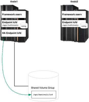
Figure 5-21: Normal operation of local and highly available Endpoints
In normal operation then, three Endpoints are running. If the cluster moves the resource group containing the highly available Endpoint from tivaix1 to tivaix2, the state of the cluster would still leave three Endpoints, as shown in Figure 5-22 on page 466.
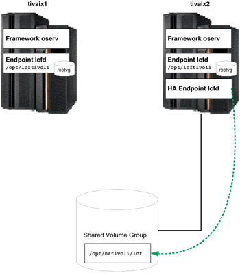
Figure 5-22: Cluster state after moving highly available Endpoint to tivaix2
However, if cluster node tivaix1 fell over to tivaix2 instead, it would leave only two Endpoint instances running, as shown in Figure 5-23 on page 467.
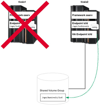
Figure 5-23: Cluster state after falling over tivaix1 to tivaix2
In each scenario in this alternate configuration, an Endpoint instance is always running on all cluster nodes that remain operational, even if HACMP on that cluster node is not running. As long as the system is powered up and the operating system functional, the local Endpoint remains to manage that system.
In this redbook we show how to install and configure a highly available Endpoint, then add a local Endpoint to the configuration. We use the same two-node cluster used throughout this document as the platform upon which we implement this configuration.
Endpoints require a Gateway in the Tivoli environment to log into so they can reach the Endpoint Manager. In our environment, we create a Gateway using the wcrtgate command, and verify the operation using the wlookup and wgateway commands as shown in Example 5-33 on page 468.
Example 5-33: Create a Gateway on tivaix1
[root@tivaix1:/home/root] wlookup -Lar Gateway [root@tivaix1:/home/root] wcrtgate -h tivaix1 -n tivaix1-gateway 1369588498.1.680#TMF_Gateway::Gateway# [root@tivaix1:/home/root] wlookup -Lar Gateway tivaix1-gateway [root@tivaix1:/home/root] wgateway tivaix1-gateway describe Object : 1369588498.1.680#TMF_Gateway::Gateway# Protocols : TCPIP Hostname : tivaix1 TCPIP Port : 9494 Session Timeout : 300 Debug level : 0 Start Time : 2003/12/22-18:53:05 Log Dir : /opt/hativoli/spool/tivaix1.db Log Size : 1024000 RPC Threads : 250 Max. Con. Jobs : 200 Gwy Httpd : Disabled mcache_bwcontrol : Disabled
In Example 5-33, we create a Gateway named tivaix1-gateway on the Managed Node tivaix1. Best practice is to design and implement multiple sets of Gateways, each set geographically dispersed when possible, to ensure that Endpoints always have a Gateway to log into.
Gateways are closely related to repeaters. Sites that use IBM Tivoli Configuration Manager might want to consider using two parallel sets of Gateways to enable simultaneous use of inventory and software distribution operations, which require different bandwidth throttling characteristics. See Tivoli Enterprise Installation Guide Version 4.1, GC32-0804, for more information about how to design a robust Gateway architecture.
As long as at least one Gateway is created, all Endpoints in a Tivoli Enterprise installation can log into that Gateway. To install a highly available Endpoint:
-
Use the wlookup command to verify that the Endpoint does not already exist.
In our environment, no Endpoints have been created yet, so the command does not return any output, as shown in Example 5-34.
Example 5-34: Verify no Endpoints exist within a Tivoli Enterprise installation
[root@tivaix1:/home/root] wlookup -Lar Endpoint [root@tivaix1:/home/root]
-
Use the winstlcf command as shown in Example 5-35 to install the Endpoint. Refer to Tivoli Management Framework Reference Manual Version 4.1, SC32-0806 for details about how to use the winstlcf command.
Example 5-35: Install a highly available Endpoint on cluster node tivaix1
[root@tivaix1:/home/root] winstlcf -d /opt/hativoli/lcf -g tivaix1 -n hativoli \ -v tivaix1_svc Trying tivaix1_svc... password for root: ********** sh -c ' echo "__START_HERE__" uname -m || hostinfo | grep NeXT uname -r || hostinfo | grep NeXT uname -s || hostinfo | grep NeXT uname -v || hostinfo | grep NeXT cd /tmp mkdir .tivoli.lcf.tmp.16552 cd .tivoli.lcf.tmp.16552 tar -xBf - > /dev/null || tar -xf - tar -xBf tivaix1_svc-16552-lcf.tar generic/epinst.sh tivaix1_svc-16552-lcf.env > /dev/null || tar -xf tivaix1_svc-16552-lcf.tar generic/epinst.sh tivaix1_svc-16552-lcf.env sh -x generic/epinst.sh tivaix1_svc-16552-lcf.env tivaix1_svc-16552-lcf.tar cd .. rm -rf .tivoli.lcf.tmp.16552 ' ********** AIX:2:5:0001813F4C00 locating files in /usr/local/Tivoli/bin/lcf_bundle.41000... locating files in /usr/local/Tivoli/bin/lcf_bundle... Ready to copy files to host tivaix1_svc: destination: tivaix1_svc:/opt/hativoli/lcf source: tivaix1:/usr/local/Tivoli/bin/lcf_bundle.41000 files: generic/lcfd.sh generic/epinst.sh generic/as.sh generic/lcf_env.sh generic/lcf_env.csh generic/lcf_env.cmd generic/lcf.inv bin/aix4-r1/mrt/lcfd lib/aix4-r1/libatrc.a lib/aix4-r1/libcpl272.a lib/aix4-r1/libdes272.a lib/aix4-r1/libmd2ep272.a lib/aix4-r1/libmrt272.a lib/aix4-r1/libtis272.a lib/aix4-r1/libio.a lib/aix4-r1/libtos.a lib/aix4-r1/libtoslog.a lib/aix4-r1/libtthred.a source: tivaix1:/usr/local/Tivoli/bin/lcf_bundle files: lib/aix4-r1/libmrt.a lib/aix4-r1/libcpl.a lib/aix4-r1/libdes.a Continue? [yYna?]y Tivoli Light Client Framework starting on tivaix1_svc Dec 22 19:00:53 1 lcfd Command line argv[0]='/opt/hativoli/lcf/bin/aix4-r1/mrt/lcfd' Dec 22 19:00:53 1 lcfd Command line argv[1]='-Dlcs.login_interfaces=tivaix1_svc' Dec 22 19:00:53 1 lcfd Command line argv[2]='-n' Dec 22 19:00:53 1 lcfd Command line argv[3]='hativoli' Dec 22 19:00:53 1 lcfd Command line argv[4]='-Dlib_dir=/opt/hativoli/lcf/lib/aix4-r1' Dec 22 19:00:53 1 lcfd Command line argv[5]='-Dload_dir=/opt/hativoli/lcf/bin/aix4-r1/mrt' Dec 22 19:00:53 1 lcfd Command line argv[6]='-C/opt/hativoli/lcf/dat/1' Dec 22 19:00:53 1 lcfd Command line argv[7]='-Dlcs.machine_name=tivaix1_svc' Dec 22 19:00:53 1 lcfd Command line argv[8]='-Dlcs.login_interfaces=tivaix1' Dec 22 19:00:53 1 lcfd Command line argv[9]='-n' Dec 22 19:00:53 1 lcfd Command line argv[10]='hativoli' Dec 22 19:00:53 1 lcfd Starting Unix daemon Performing auto start configuration Done. + set -a + WINSTENV=tivaix1_svc-16552-lcf.env + [ -z tivaix1_svc-16552-lcf.env ] + . ./tivaix1_svc-16552-lcf.env + INTERP=aix4-r1 + LCFROOT=/opt/hativoli/lcf + NOAS= + ASYNCH= + DEBUG= + LCFOPTS= -Dlcs.login_interfaces=tivaix1_svc -n hativoli + NOTAR= + MULTIINSTALL= + BULK_COUNT= + BULK_PORT= + HOSTNAME=tivaix1_svc + VERBOSE=1 + PRESERVE= + LANG= + LC_ALL= + LCFDVRMP=LCF41015 + rm -f ./tivaix1_svc-16552-lcf.env + [ aix4-r1 != w32-ix86 -a aix4-r1 != w32-axp ] + umask 022 + + pwd stage=/tmp/.tivoli.lcf.tmp.16552 + [ -n ] + [ aix4-r1 = w32-ix86 -o aix4-r1 = os2-ix86 -o aix4-r1 = w32-axp ] + [ -d /opt/hativoli/lcf/bin/aix4-r1 ] + [ ! -z ] + MKDIR_CMD=/bin/mkdir -p /opt/hativoli/lcf/dat + [ -d /opt/hativoli/lcf/dat ] + /bin/mkdir -p /opt/hativoli/lcf/dat + [ aix4-r1 != w32-ix86 -a aix4-r1 != w32-axp -a aix4-r1 != os2-ix86 ] + chmod 755 /opt/hativoli/lcf/dat + cd /opt/hativoli/lcf + [ aix4-r1 = os2-ix86 -a ! -d /tmp ] + [ -n ] + [ aix4-r1 = w32-ix86 -a -z ] + [ aix4-r1 = w32-axp -a -z ] + mv generic/lcf.inv bin/aix4-r1/mrt/LCF41015.SIG + PATH=/usr/bin:/etc:/usr/sbin:/usr/ucb:/usr/bin/X11:/sbin:/usr/java130/jre/bin:/usr/java130/bin: /opt/hativoli/lcf/generic + export PATH + [ -n ] + [ -n ] + K=1 + fixup=1 + [ 1 -gt 0 ] + unset fixup + [ -n ] + [ -n ] + [ -n ] + [ -n ] + [ -z ] + port=9494 + [ aix4-r1 = w32-ix86 -o aix4-r1 = w32-axp ] + ET=/etc/Tivoli/lcf + + getNextDirName /opt/hativoli/lcf/dat /etc/Tivoli/lcf uniq=1 + LCF_DATDIR=/opt/hativoli/lcf/dat/1 + [ aix4-r1 != openstep4-ix86 ] + mkdir -p dat/1 + s=/opt/hativoli/lcf/dat/1/lcfd.sh + cp /opt/hativoli/lcf/generic/lcfd.sh /opt/hativoli/lcf/dat/1/lcfd.sh + sed -e s!@INTERP@!aix4-r1!g -e s!@LCFROOT@!/opt/hativoli/lcf!g -e s!@LCF_DATDIR@!/opt/hativoli/lcf/dat/1!g + 0< /opt/hativoli/lcf/dat/1/lcfd.sh 1> t + mv t /opt/hativoli/lcf/dat/1/lcfd.sh + [ aix4-r1 != w32-ix86 -a aix4-r1 != w32-axp -a aix4-r1 != os2-ix86 ] + chmod 755 /opt/hativoli/lcf/dat/1/lcfd.sh + chmod 755 /opt/hativoli/lcf/bin/aix4-r1/mrt/lcfd + chmod 755 /opt/hativoli/lcf/lib/aix4-r1/libatrc.a /opt/hativoli/lcf/lib/aix4-r1/libcpl.a /opt/hativoli/lcf/lib/aix4-r1/libcpl272.a /opt/hativoli/lcf/lib/aix4-r1/libdes.a /opt/hativoli/lcf/lib/aix4-r1/libdes272.a /opt/hativoli/lcf/lib/aix4-r1/libio.a /opt/hativoli/lcf/lib/aix4-r1/libmd2ep272.a /opt/hativoli/lcf/lib/aix4-r1/libmrt.a /opt/hativoli/lcf/lib/aix4-r1/libmrt272.a /opt/hativoli/lcf/lib/aix4-r1/libtis272.a /opt/hativoli/lcf/lib/aix4-r1/libtos.a /opt/hativoli/lcf/lib/aix4-r1/libtoslog.a /opt/hativoli/lcf/lib/aix4-r1/libtthred.a + s=/opt/hativoli/lcf/generic/lcf_env.sh + [ -f /opt/hativoli/lcf/generic/lcf_env.sh ] + sed -e s!@LCFROOT@!/opt/hativoli/lcf!g + 0< /opt/hativoli/lcf/generic/lcf_env.sh 1> t + mv t /opt/hativoli/lcf/generic/lcf_env.sh + label=tivaix1_svc + [ 1 -ne 1 ] + [ aix4-r1 = w32-ix86 -o aix4-r1 = w32-axp ] + [ -n ] + /opt/hativoli/lcf/dat/1/lcfd.sh install -C/opt/hativoli/lcf/dat/1 -Dlcs.machine_name=tivaix1_svc -Dlcs.login_interfaces=tivaix1 -n hativoli + + expr 1 - 1 K=0 + [ 0 -gt 0 ] + set +e + ET=/etc/Tivoli/lcf/1 + [ aix4-r1 = w32-ix86 -o aix4-r1 = w32-axp ] + [ aix4-r1 != openstep4-ix86 ] + [ ! -d /etc/Tivoli/lcf/1 ] + mkdir -p /etc/Tivoli/lcf/1 + mv /opt/hativoli/lcf/generic/lcf_env.sh /etc/Tivoli/lcf/1/lcf_env.sh + sed -e s!@INTERP@!aix4-r1!g -e s!@LCFROOT@!/opt/hativoli/lcf!g -e s!@LCF_DATDIR@!/opt/hativoli/lcf/dat/1!g + 0< /etc/Tivoli/lcf/1/lcf_env.sh 1> /etc/Tivoli/lcf/1/lcf_env.sh.12142 + mv /etc/Tivoli/lcf/1/lcf_env.sh.12142 /etc/Tivoli/lcf/1/lcf_env.sh + [ aix4-r1 = w32-ix86 -o aix4-r1 = w32-axp -o aix4-r1 = os2-ix86 ] + mv /opt/hativoli/lcf/generic/lcf_env.csh /etc/Tivoli/lcf/1/lcf_env.csh + sed -e s!@INTERP@!aix4-r1!g -e s!@LCFROOT@!/opt/hativoli/lcf!g -e s!@LCF_DATDIR@!/opt/hativoli/lcf/dat/1!g + 0< /etc/Tivoli/lcf/1/lcf_env.csh 1> /etc/Tivoli/lcf/1/lcf_env.csh.12142 + mv /etc/Tivoli/lcf/1/lcf_env.csh.12142 /etc/Tivoli/lcf/1/lcf_env.csh + cp /etc/Tivoli/lcf/1/lcf_env.csh /etc/Tivoli/lcf/1/lcf_env.sh /opt/hativoli/lcf/dat/1 + [ aix4-r1 = os2-ix86 ] + [ -z ] + sh /opt/hativoli/lcf/generic/as.sh 1 + echo 1 + 1> /etc/Tivoli/lcf/.instance + echo Done.
In our environment, we used the -d flag option to specify the installation destination of the Endpoint, the -g flag option to specify the Gateway we create, the -n flag option to specify the name of the Endpoint, the -v flag option for verbose output, and we use the IP hostname tivaix1_svc to bind the Endpoint to the IP service label of the cluster node.
-
Use the wlookup and wep commands as shown in Example 5-36 to verify the installation of the highly available Endpoint.
Example 5-36: Verify installation of highly available Endpoint
[root@tivaix1:/home/root] wlookup -Lar Endpoint hativoli [root@tivaix1:/home/root] wep ls G 1369588498.1.680 tivaix1-gateway 1369588498.2.522+#TMF_Endpoint::Endpoint# hativoli [root@tivaix1:/home/root] wep hativoli object 1369588498.2.522+#TMF_Endpoint::Endpoint# label hativoli version 41014 id 0001813F4C00 gateway 1369588498.1.680#TMF_Gateway::Gateway# pref_gateway 1369588498.1.680#TMF_Gateway::Gateway# netload OBJECT_NIL interp aix4-r1 login_mode desktop, constant protocol TCPIP address 192.168.100.101+9495 policy OBJECT_NIL httpd tivoli:r)T!*`un alias OBJECT_NIL crypt_mode NONE upgrade_mode enable last_login_time 2003/12/22-19:00:54 last_migration_time 2003/12/22-19:00:54 last_method_time NOT_YET_SET
-
If this is the first time an Endpoint is installed on the system, the Lightweight Client Framework (LCF) environment file is installed in the /etc/Tivoli/lcf/1 directory, as shown in Example 5-37 on page 474. The directory with the highest number in the /etc/Tivoli/lcf directory is the latest installed environment files directory. Identify this directory and record it.
Example 5-37: Identify directory location of LCF environment file
[root@tivaix1:/home/root] ls /etc/Tivoli/lcf/1 ./ ../ lcf_env.csh lcf_env.sh
Tip Best practice is to delete all unused instances of the LCF environment directories. This eliminates the potential for misleading configurations.
If you are unsure of which directory contains the appropriate environment files, use the grep command as shown in Example 5-38 to identify which instance of an Endpoint an LCF environment file is used for.
Example 5-38: Identify which instance of an Endpoint an LCF environment file is used for
[root@tivaix1:/home/root] grep LCFROOT= /etc/Tivoli/lcf/1/lcf_env.sh LCFROOT="/opt/hativoli/lcf"
Important: Ensure the instance of a highly available Endpoint is the same on all cluster nodes that the Endpoint can fall over to. This enables scripts to be the same on every cluster node.
-
Stop the new Endpoint to prepare it for HACMP to start and stop it. Use the ps and grep commands to identify the running instances of Endpoints, source in the LCF environment, use the lcfd.sh command to stop the Endpoint (the environment that is sourced in identifies the instance of the Endpoint that is stopped), and use the ps and grep commands to verify that the Endpoint is stopped, as shown in Example 5-39.
Example 5-39: Stop an instance of an Endpoint
[root@tivaix1:/home/root] ps -ef | grep lcf | grep -v grep root 21520 1 0 Dec 22 - 0:00 /opt/hativoli/bin/aix4-r1/mrt/lcfd -Dlcs.login_interfaces=tivaix1_svc -n hativoli -Dlib_dir=/opt/hativoli/lib/aix4-r1 -Dload_dir=/opt/hativoli/bin/aix4-r1/mrt -C/opt/hativoli/dat/1 -Dlcs.machine_name=tivaix1_svc -Dlcs.login_interfaces=tivaix1 -n hativoli [root@tivaix1:/home/root] . /etc/Tivoli/lcf/1/lcf_env.sh [root@tivaix1:/home/root] lcfd.sh stop [root@tivaix1:/home/root] ps -ef | grep lcf | grep -v grep
Disable automatic start
Disable the automatic start of any highly available Tivoli server, Managed Node, or Endpoint so that instead of starting as soon as the system restarts, they start under the control of HACMP.
Endpoint installations configure the Endpoint to start every time the system restarts. High availability implementations need to start and stop highly available Endpoints after HACMP is running, so the automatic start after system restart needs to be disabled. Determine how an Endpoint starts on your platform after a system restart and disable it.
In our environment, the highly available Endpoint is installed on an IBM AIX system. Under IBM AIX, the file /etc/rc.tman starts an Endpoint, where n is the instance of an Endpoint that is installed. Example 5-40 shows the content of this file. We remove the file to disable automatic start after system restart.
Example 5-40: Identify how an Endpoint starts during system restart
[root@tivaix1:/etc] cat /etc/rc.tma1 #!/bin/sh # # Start the Tivoli Management Agent # if [ -f /opt/hativoli/dat/1/lcfd.sh ]; then /opt/hativoli/dat/1/lcfd.sh start fi
The oserv.rc program starts Tivoli servers and Managed Nodes. In our environment, the highly available Tivoli server is installed on an IBM AIX system. We use the find command as shown in Example 5-41 to identify the files in the /etc directory used to start the object dispatcher. The files (highlighted in italics) are: /etc/inittab and /etc/inetd.conf. We remove the lines found by the find command to disable the automatic start mechanism.
Example 5-41: Find all instances where IBM Tivoli Management Framework is started
[root@tivaix1:/etc] find /etc -type f -exec grep 'oserv.rc' {} \; -print oserv:2:once:/etc/Tivoli/oserv.rc start > /dev/null 2>&1 /etc/inittab objcall dgram udp wait root /etc/Tivoli/oserv.rc /etc/Tivoli/oserv.rc inetd /etc/inetd.conf You can use the same find command to determine how the object dispatcher starts on your platform. Use the following find command to search for instances of the string "lcfd.sh" in the files in the /etc directory if you need to identify the files where the command is used to start an Endpoint:
find /etc -type f -exec grep 'lcfd.sh' {} \; -print Note that the line containing the search string appears first, followed by the file location.
5.1.8 Configure HACMP
After verifying that the installation of IBM Tivoli Management Framework (whether it is a Tivoli server, Managed Node, or Endpoint) you want to make highly available correctly functions, then install and configure HACMP on the system. If IBM Tivoli Management Framework subsequently fails to start or function properly, you will know that it is highly likely the cause is due to an HACMP issue instead of an IBM Tivoli Management Framework issue.
| Restriction: | These procedures are mutually exclusive from the instructions given in Chapter 4, "IBM Tivoli Workload Scheduler implementation in a cluster" on page 183. While some steps are the same, you can either implement either the scenario given in that chapter, or this chapter, but you cannot implement both at the same time. |
In this section we show how to install and configure HACMP for an IBM Tivoli Management Framework Tivoli server.
Install HACMP
Complete the procedures in "Install HACMP" on page 113.
Configure HACMP topology
Complete the procedures in "Configure HACMP topology" on page 219 to define the cluster topology.
Configure service IP labels/addresses
Complete the procedures in "Configure HACMP service IP labels/addresses" on page 221 to configure service IP labels and addresses.
Configure application servers
An application server is a cluster resource used to control an application that must be kept highly available. Configuring an application server does the following:
-
It associates a meaningful name with the server application. For example, you could give an installation of IBM Tivoli Management Framework a name such as itmf. You then use this name to refer to the application server when you define it as a resource.
-
It points the cluster event scripts to the scripts that they call to start and stop the server application.
-
It allows you to then configure application monitoring for that application server.
We show in "Add custom HACMP start and stop scripts" on page 485 how to write the start and stop scripts for IBM Tivoli Management Framework.
| Note | Ensure that the server start and stop scripts exist on all nodes that participate as possible owners of the resource group where this application server resides. |
Complete the following steps to create an application server on any cluster node:
-
Enter: smitty hacmp.
-
Go to Initialization and Standard Configuration -> Configure Resources to Make Highly Available -> Configure Application Servers and press Enter. The Configure Resources to Make Highly Available SMIT screen is displayed as shown in Figure 5-24.
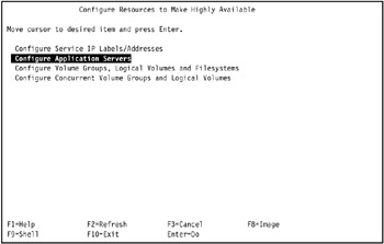
Figure 5-24: Configure Resources to Make Highly Available SMIT screen -
Go to Configure Application Servers and press Enter. The Configure Application Servers SMIT screen is displayed as shown in Figure 5-25.
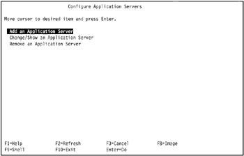
Figure 5-25: Configure Application Servers SMIT screen -
Go to Add an Application Server and press Enter. The Add Application Server SMIT screen is displayed as shown in Figure 5-26 on page 479. Enter field values as follows:
Server Name
Enter an ASCII text string that identifies the server. You will use this name to refer to the application server when you define resources during node configuration. The server name can include alphabetic and numeric characters and underscores. Use no more than 64 characters.
Start Script
Enter the name of the script and its full pathname (followed by arguments) called by the cluster event scripts to start the application server. (Maximum 256 characters.) This script must be in the same location on each cluster node that might start the server. The contents of the script, however, may differ.
Stop Script
Enter the full pathname of the script called by the cluster event scripts to stop the server. (Maximum 256 characters.) This script must be in the same location on each cluster node that may start the server. The contents of the script, however, may differ.
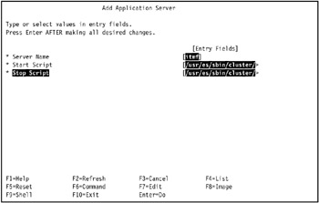
Figure 5-26: Fill out the Add Application Server SMIT screen for application server itmfAs shown in Figure 5-26, in our environment on tivaix1 we named the instance of IBM Tivoli Management Framework that normally runs on that cluster node "itmf" (for IBM Tivoli Management Framework). Note that no mention is made of the cluster nodes when defining an application server. We only mention the cluster node so you are familiar with the conventions we use in our environment.
For the start script of application server itmf, we enter the following in the Start Script field:
/usr/es/sbin/cluster/utils/start_itmf.sh
The stop script of this application server is:
/usr/es/sbin/cluster/utils/stop_itmf.sh
This is entered in the Stop Script field.
-
Press Enter to add this information to the ODM on the local node.
-
Repeat the procedure for all additional application servers.
For our environment, there are no further application servers to configure.
Configure the application monitoring
HACMP can monitor specified applications and automatically take action to restart them upon detecting process death or other application failures.
| Note | If a monitored application is under control of the system resource controller, check to be certain that action:multi are -O and -Q. The -O specifies that the subsystem is not restarted if it stops abnormally. The -Q specifies that multiple instances of the subsystem are not allowed to run at the same time. These values can be checked using the following command:
lssrc -Ss Subsystem | cut -d : -f 10,11 If the values are not -O and -Q, then they must be changed using the chssys command. |
You can select either of two application monitoring methods:
-
Process application monitoring detects the death of one or more processes of an application, using RSCT Event Management.
-
Custom application monitoring checks the health of an application with a custom monitor method at user-specified polling intervals.
Process monitoring is easier to set up, as it uses the built-in monitoring capability provided by RSCT and requires no custom scripts. However, process monitoring may not be an appropriate option for all applications. Custom monitoring can monitor more subtle aspects of an application's performance and is more customizable, but it takes more planning, as you must create the custom scripts.
We show you in this section how to configure process monitoring for IBM Tivoli Management Framework. Remember that an application must be defined to an application server before you set up the monitor.
For IBM Tivoli Management Framework, we configure process monitoring for the oserv process because it will always run under normal conditions. If it fails, we want the cluster to automatically fall over, and not attempt to restart oserv. Because oserv starts very quickly, we only give it 60 seconds to start before monitoring begins. For cleanup and restart scripts, we will use the same scripts as the start and stop scripts discussed in "Add custom HACMP start and stop scripts" on page 485.
Set up your process application monitor as follows:
-
Enter: smit hacmp.
-
Go to Extended Configuration -> Extended Resource Configuration -> Extended Resources Configuration -> Configure HACMP Application Monitoring -> Configure Process Application Monitor -> Add Process Application Monitor and press Enter. A list of previously defined application servers appears.
-
Select the application server for which you want to add a process monitor.
In our environment, we selected itmf, as shown in Figure 5-27.
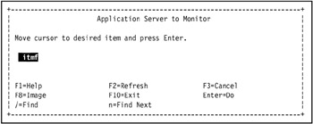
Figure 5-27: Select an application server to monitor -
In the Add Process Application Monitor screen, fill in the field values as follows:
Monitor Name
This is the name of the application monitor. If this monitor is associated with an application server, the monitor has the same name as the application server. This field is informational only and cannot be edited.
Application Server Name
(This field can be chosen from the picklist. It is already filled with the name of the application server you selected.)
Processes to Monitor
Specify the process(es) to monitor. You can type more than one process name. Use spaces to separate the names.
Note To be sure you are using correct process names, use the names as they appear from the ps -el command (not ps -f), as explained in the section "Identifying Correct Process Names" in High Availability Cluster Multi-Processing for AIX Administration and Troubleshooting Guide Version 5.1, SC23-4862.
Process Owner
Specify the user id of the owner of the processes specified above, for example, root. Note that the process owner must own all processes to be monitored.
Instance Count
Specify how many instances of the application to monitor. The default is 1 instance. The number of instances must match the number of processes to monitor exactly. If you put 1 instance, and another instance of the application starts, you will receive an application monitor error.
Note This number must be 1 if you have specified more than one process to monitor (one instance for each process).
Stabilization Interval
Specify the time (in seconds) to wait before beginning monitoring. For instance, with a database application, you may wish to delay monitoring until after the start script and initial database search have been completed. You may need to experiment with this value to balance performance with reliability.
Note In most circumstances, this value should not be zero.
Restart Count
Specify the restart count, that is the number of times to attempt to restart the application before taking any other actions. The default is 3.
Note Make sure you enter a Restart Method if your Restart Count is any non-zero value.
Restart Interval
Specify the interval (in seconds) that the application must remain stable before resetting the restart count. Do not set this to be shorter than (Restart Count) x (Stabilization Interval). The default is 10% longer than that value. If the restart interval is too short, the restart count will be reset too soon and the desired fallover or notify action may not occur when it should.
Action on Application Failure
Specify the action to be taken if the application cannot be restarted within the restart count. You can keep the default choice notify, which runs an event to inform the cluster of the failure, or select fallover, in which case the resource group containing the failed application moves over to the cluster node with the next highest priority for that resource group.
Refer to "Note on the Fallover Option and Resource Group Availability" in High Availability Cluster Multi-Processing for AIX Administration and Troubleshooting Guide Version 5.1, SC23-4862 for more information.
Notify Method
(Optional) Define a notify method that will run when the application fails. This custom method runs during the restart process and during notify activity.
Cleanup Method
(Optional) Specify an application cleanup script to be invoked when a failed application is detected, before invoking the restart method. The default is the application server stop script defined when the application server was set up.
Note With application monitoring, since the application is already stopped when this script is called, the server stop script may fail.
Restart Method
(Required if Restart Count is not zero.) The default restart method is the application server start script defined previously, when the application server was set up. You can specify a different method here if esired.
In our environment, we entered the process /usr/hativoli/bin/aix4-r1/bin/oserv in the Process to Monitor field, root in the Process Owner field, 60 in the Stabilization Interval field, 0 in the Restart Count field, and fallover in the Action on Application Failure field; all other fields were left as is, as shown in Figure 5-28.
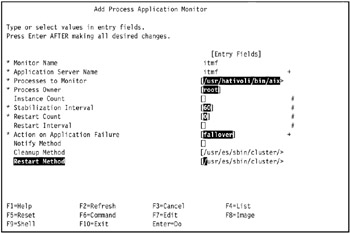
Figure 5-28: Add Process Application Monitor SMIT screen for application server itmf -
Press Enter after you have entered the desired information.
The values are then checked for consistency and entered into the ODM. hen the resource group comes online, the application monitor starts.
In our environment that we use for this Redbook, the COMMAND STATUS MIT screen displays two warnings as shown in Figure 5-29 on page 485, which we safely ignore because the default values applied are the desired values.
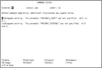
Figure 5-29: COMMAND STATUS SMIT screen after creating HACMP process application monitor -
Repeat the operation for remaining application servers.
In our environment that we use for this Redbook, there are no other IBM Tivoli Management Framework application servers to configure.
You can create similar application monitors for a highly available Endpoint.
Add custom HACMP start and stop scripts
For IBM Tivoli Management Framework, custom scripts for HACMP are required to start and stop the application server (in this case, the object dispatcher for Managed Nodes or the lightweight client framework for Endpoints). These are used when HACMP starts an application server that is part of a resource group, and gracefully shuts down the application server when a resource group is taken offline or moved. The stop script of course does not get an opportunity to execute if a cluster node is unexpectedly halted. We developed the following basic versions of the scripts for our environment. You may need to write your own version to accommodate your site's specific requirements.
The following example shows a start script for a highly available object dispatcher (Managed Node or Tivoli server).
Example 5-42: Script to start highly available IBM Tivoli Management Framework
#!/bin/sh # # Start IBM Tivoli Management Framework if [ -f /etc/Tivoli/setup_env.sh ] ; then . /etc/Tivoli/setup_env.sh /etc/Tivoli/oserv.rc start else exit 1 fi
The following example shows a stop script for a highly available object dispatcher.
Example 5-43: Script to stop highly available IBM Tivoli Management Framework
#!/bin/sh # # Shut down IBM Tivoli Management Framework odadmin shutdown 1
The following example shows a start script for a highly available Endpoint.
Example 5-44: Start script for highly available Endpoint
#!/bin/sh # # Starts the highly available Endpoint if [ -f /etc/Tivoli/lcf/1/lcf_env.sh ] ; then . /etc/Tivoli/lcf/1/lcf_env.sh lcfd.sh start else exit 1 fi
The stop script for a highly available Endpoint is similar, except that it passes the argument "stop" in the call to lcfd.sh, as shown in the following example.
Example 5-45: Stop script for highly available Endpoint
#!/bin/sh # # Stops the highly available Endpoint if [ -f /etc/Tivoli/lcf/1/lcf_env.sh ] ; then . /etc/Tivoli/lcf/1/lcf_env.sh lcfd.sh stop else exit 1 fi
If you want to implement a highly available object dispatcher and Endpoint in the same resource group, merge the corresponding start and stop scripts into a single script.
The configuration we show in this redbook is for a hot standby cluster, so using the same start and stop scripts on all cluster nodes is sufficient. Mutual takeover configurations will need to use more sophisticated scripts that determine the state of the cluster and start (or stop) the appropriate instances of object dispatchers and Endpoints.
Modify /etc/hosts and the name resolution order
Complete the procedures in "Modify /etc/hosts and name resolution order" on page 451 to modify /etc/hosts and name resolution order on both tivaix1 and tivaix2.
Configure HACMP networks and heartbeat paths
Complete the procedures in "Configure HACMP networks and heartbeat paths" on page 254 to configure HACMP networks and heartbeat paths.
Configure HACMP resource group
This creates a container to organize HACMP resources into logical groups that are defined later. Refer to High Availability Cluster Multi-Processing for AIX Concepts and Facilities Guide Version 5.1, SC23-4864 for an overview of types of resource groups you can configure in HACMP 5.1. Refer to the chapter on planning resource groups in High Availability Cluster Multi-Processing for AIX, Planning and Installation Guide Version 5.1, SC23-4861-00 for further planning information. You should have your planning worksheets in hand.
Using the standard path, you can configure resource groups that use the basic management policies. These policies are based on the three predefined types of startup, fallover, and fallback policies: cascading, rotating, concurrent. In addition to these, you can also configure custom resource groups for which you can specify slightly more refined types of startup, fallover and fallback policies.
Once the resource groups are configured, if it seems necessary for handling certain applications, you can use the Extended Configuration path to change or refine the management policies of particular resource groups (especially custom resource groups).
Configuring a resource group involves two phases:
-
Configuring the resource group name, management policy, and the nodes that can own it.
-
Adding the resources and additional attributes to the resource group.
Refer to your planning worksheets as you name the groups and add the resources to each one.
To create a resource group:
-
Enter smit hacmp.
-
On the HACMP menu, select Initialization and Standard Configuration > Configure HACMP Resource Groups >Add a Standard Resource Group and press Enter.
You are prompted to select a resource group management policy.
-
Select Cascading, Rotating, Concurrent or Custom and press Enter.
For our environment we use Cascading.
Depending on the previous selection, you will see a screen titled Add a Cascading | Rotating | Concurrent | Custom Resource Group. The screen will only show options relevant to the type of the resource group you selected. If you select custom, you will be asked to refine the startup, fallover, and fallback policy before continuing.
-
Enter the field values as follows for a cascading, rotating, or concurrent resource group:
Resource Group Name
Enter the desired name. Use no more than 32 alphanumeric characters or underscores; do not use a leading numeric. Do not use reserved words. See Chapter 6, section "List of Reserved Words" in High Availability Cluster Multi-Processing for AIX Administration and Troubleshooting Guide Version 5.1, SC23-4862. Duplicate entries are not allowed.
Participating Node Names
Enter the names of the nodes that can own or take over this resource group. Enter the node with the highest priority for ownership first, followed by the nodes with the lower priorities, in the desired order. Leave a space between node names. For example, NodeA NodeB NodeX.
If you choose to define a custom resource group, you define additional fields. We do not use custom resource groups in this Redbook for simplicity of presentation.
Figure 5-30 shows how we configured resource group itmf_rg in the environment implemented by this Redbook. We use this resource group to contain the instance of IBM Tivoli Management Framework normally running on tivaix1.
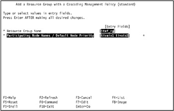
Figure 5-30: Configure resource group rg1
Configure resources in the resource groups
Once you have defined a resource group, you assign resources to it. SMIT can list possible shared resources for the node if the node is powered on (helping you to avoid configuration errors).
When you are adding or changing resources in a resource group, HACMP displays only valid choices for resources, based on the resource group management policies that you have selected.
To assign the resources for a resource group:
-
Enter: smit hacmp.
-
Go to Initialization and Standard Configuration -> Configure HACMP Resource Groups -> Change/Show Resources for a Standard Resource Group and press Enter to display a list of defined resource groups.
-
Select the resource group you want to configure and press Enter. SMIT returns the screen that matches the type of resource group you selected, with the Resource Group Name, and Participating Node Names (Default Node Priority) fields filled in.
Note SMIT displays only valid choices for resources, depending on the type of resource group that you selected. The fields are slightly different for custom, non-concurrent, and concurrent groups.
If the participating nodes are powered on, you can press F4 to list the shared resources. If a resource group/node relationship has not been defined, or if a node is not powered on, F4 displays the appropriate warnings.
-
Enter the field values as follows:
Service IP Label/IP Addresses
(Not an option for concurrent or custom concurrent-like resource groups.) List the service IP labels to be taken over when this resource group is taken over. Press F4 to see a list of valid IP labels. These include addresses which rotate or may be taken over.
Filesystems (empty is All for specified VGs)
(Not an option for concurrent or custom concurrent-like resource groups.) If you leave the Filesystems (empty is All for specified VGs) field blank and specify the shared volume groups in the Volume Groups field below, all file systems will be mounted in the volume group. If you leave the Filesystems field blank and do not specify the volume groups in the field below, no file systems will be mounted.
You may also select individual file systems to include in the resource group. Press F4 to see a list of the filesystems. In this case only the specified file systems will be mounted when the resource group is brought online.
Filesystems (empty is All for specified VGs) is a valid option only for non-concurrent resource groups.
Volume Groups
(If you are adding resources to a non-concurrent resource group) Identify the shared volume groups that should be varied on when this resource group is acquired or taken over. Select the volume groups from the picklist or enter desired volume groups names in this field.
Pressing F4 will give you a list of all shared volume groups in the resource group and the volume groups that are currently available for import onto the resource group nodes.
Specify the shared volume groups in this field if you want to leave the field Filesystems (empty is All for specified VGs) blank and to mount all filesystems in the volume group. If you specify more than one volume group in this field, then all filesystems in all specified volume groups will be mounted; you cannot choose to mount all filesystems in one volume group and not to mount them in another.
For example, in a resource group with two volume groups, vg1 and vg2, if the field Filesystems (empty is All for specified VGs) is left blank, then all the file systems in vg1 and vg2 will be mounted when the resource group is brought up. However, if the field Filesystems (empty is All for specified VGs) has only file systems that are part of the vg1 volume group, then none of the file systems in vg2 will be mounted, because they were not entered in the Filesystems (empty is All for specified VGs) field along with the file systems from vg1.
If you have previously entered values in the Filesystems field, the appropriate volume groups are already known to the HACMP software.
Concurrent Volume Groups
(Appears only if you are adding resources to a concurrent or custom concurrent-like resource group.) Identify the shared volume groups that can be accessed simultaneously by multiple nodes. Select the volume groups from the picklist, or enter desired volume groups names in this field.
If you previously requested that HACMP collect information about the appropriate volume groups, then pressing F4 will give you a list of all existing concurrent capable volume groups that are currently available in the resource group, and concurrent capable volume groups available to be imported onto the nodes in the resource group.
Disk fencing is turned on by default.
Application Servers
Indicate the application servers to include in the resource group. Press F4 to see a list of application servers.
Note If you are configuring a custom resource group, and choose to use a dynamic node priority policy for a cascading-type custom resource group, you will see the field where you can select which one of the three predefined node priority policies you want to use.
In our environment, we defined resource group rg1 as shown in Figure 5-31 on page 493.
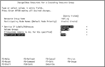
Figure 5-31: Define resource group rg1For resource group rg1, we assign tivaix1_svc as the service IP label, tiv_vg1 as the sole volume group to use, and tws_svr1 for the application server.
-
Press Enter to add the values to the HACMP ODM.
-
Repeat the operation for other resource groups to configure.
In our environment, we did not have any further resource groups to configure.
Configure cascading without fallback, other attributes
We configure all resource groups in our environment for cascading without fallback (CWOF) so IBM Tivoli Management Framework can be given enough time to quiesce before falling back. This is part of the extended resource group configuration.
We use this step to also configure other attributes of the resource groups like the associated shared volume group and filesystems.
To configure CWOF and other resource group attributes:
-
Enter: smit hacmp.
-
Go to Extended Configuration -> Extended Resource Configuration -> Extended Resource Group Configuration -> Change/Show Resources and Attributes for a Resource Group and press Enter.
SMIT displays a list of defined resource groups.
-
Select the resource group you want to configure and press Enter. SMIT returns the screen that matches the type of resource group you selected, with the Resource Group Name, Inter-site Management Policy, and Participating Node Names (Default Node Priority) fields filled in.
If the participating nodes are powered on, you can press F4 to list the shared resources. If a resource group/node relationship has not been defined, or if a node is not powered on, F4 displays the appropriate warnings.
-
Enter true in the Cascading Without Fallback Enabled field by pressing Tab in the field until the value is displayed (Figure 5-32).
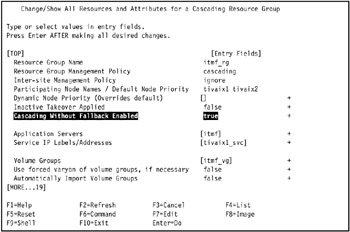
Figure 5-32: Set cascading without fallback (CWOF) for a resource group -
Repeat the operation for any other applicable resource groups.
In our environment, we applied the same operation to resource group rg2.
For the environment in this Redbook, all resources and attributes for resource group rg1 are shown in Example 5-46.
Example 5-46: All resources and attributes for resource group rg1
[TOP] [Entry Fields] Resource Group Name itmf_rg Resource Group Management Policy cascading Inter-site Management Policy ignore Participating Node Names / Default Node Priority tivaix1 tivaix2 Dynamic Node Priority (Overrides default) [] + Inactive Takeover Applied false + Cascading Without Fallback Enabled true + Application Servers [itmf] + Service IP Labels/Addresses [tivaix1_svc] + Volume Groups [itmf_vg] + Use forced varyon of volume groups, if necessary false + Automatically Import Volume Groups false + Filesystems (empty is ALL for VGs specified) [/usr/local/itmf] + Filesystems Consistency Check fsck + Filesystems Recovery Method sequential + Filesystems mounted before IP configured false + Filesystems/Directories to Export [] + Filesystems/Directories to NFS Mount [] + Network For NFS Mount [] + Tape Resources [] + Raw Disk PVIDs [] + Fast Connect Services [] + Communication Links [] + Primary Workload Manager Class [] + Secondary Workload Manager Class [] + Miscellaneous Data [] [BOTTOM]
Configure HACMP persistent node IP label/addresses
Complete the procedure in "Configure HACMP persistent node IP label/addresses" on page 272 to configure HACMP persistent node IP labels and addresses.
Configure predefined communication interfaces
Complete the procedure in "Configure predefined communication interfaces" on page 276 to configure predefined communication interfaces to HACMP.
Verify the configuration
Complete the procedure in "Verify the configuration" on page 280 to verify the HACMP configuration.
The output of the cltopinfo command for our environment is shown in Example 5-47.
Example 5-47: Output of cltopinfo command for hot standby Framework configuration
Cluster Description of Cluster: cltivoli Cluster Security Level: Standard There are 2 node(s) and 3 network(s) defined NODE tivaix1: Network net_ether_01 tivaix1_svc 9.3.4.3 tivaix2_svc 9.3.4.4 tivaix1_bt2 10.1.1.101 tivaix1_bt1 192.168.100.101 Network net_tmssa_01 tivaix1_tmssa2_01 /dev/tmssa2 NODE tivaix2: Network net_ether_01 tivaix1_svc 9.3.4.3 tivaix2_svc 9.3.4.4 tivaix2_bt1 192.168.100.102 tivaix2_bt2 10.1.1.102 Network net_tmssa_01 tivaix2_tmssa1_01 /dev/tmssa1 Resource Group itmf_rg Behavior cascading Participating Nodes tivaix1 tivaix2 Service IP Label tivaix1_svc
The output would be the same for configurations that add highly available Endpoints, because we use the same resource group in the configuration we show in this redbook.
Start HACMP Cluster services
Complete the procedure in "Start HACMP Cluster services" on page 287 to start HACMP on the cluster.
Verify HACMP status
Complete the procedure in "Verify HACMP status" on page 292 to verify HACMP is running on the cluster.
Test HACMP resource group moves
Complete the procedure in "Test HACMP resource group moves" on page 294 to test moving resource group itmf_rg from cluster node tivaix1 to tivaix2, then from tivaix2 to tivaix1.
Live test of HACMP fallover
Complete the procedure in "Live test of HACMP fallover" on page 298 to test HACMP fallover of the itmf_rg resource group. Verify the lsvg command displays the volume group itmf_vg and the command clRGinfo command displays the resource group itmf_rg.
Configure HACMP to start on system restart
Complete the procedure in "Configure HACMP to start on system restart" on page 300 to set HACMP to start when the system restarts.
Verify Managed Node fallover
When halting cluster nodes during testing in" Live test of HACMP fallover", a highly available Managed Node (or Tivoli server) will also start appropriately when the itmf_rg resource group is moved. Once you verify that a resource group's disk and network resources have moved, you must verify that the Managed Node itself functions in its new cluster node (or in HACMP terms, verify that the application server resource of the resource group is functions in the new cluster node).
In our environment, we perform the live test of HACMP operation at least twice: once to test HACMP resource group moves of disk and network resources in response to a sudden halt of a cluster node, and again while verifying the highly available Managed Node is running on the appropriate cluster node(s).
To verify that a highly available Managed Node is running during a test of a cluster node fallover from tivaix1 to tivaix2, follow these steps:
-
Log into the surviving cluster node as any user.
-
Use the odadmin command, as shown in Example 5-48 on page 498.
Example 5-48: Sample output of command to verify IBM Tivoli Management Framework is moved by HACMP
[root@tivaix1:/home/root] . /etc/Tivoli/setup_env.sh [root@tivaix1:/home/root] odadmin odlist Region Disp Flags Port IPaddr Hostname(s) 1369588498 1 ct- 94 9.3.4.3 tivaix1_svc 9.3.4.194 tivaix1,tivaix1.itsc.austin.ibm.com
The command should be repeated while testing that CWOF works. If CWOF works, then the output will remain identical after the halted cluster node reintegrates with the cluster.
The command should be repeated again to verify that falling back works. In our environment, after moving a resource group back to the reintegrated cluster node so the cluster is in its normal operating mode (tivaix1 has the itmf_rg resource group, and tivaix2 has no resource group), the output of the odadmin command on tivaix1 verifies that the Managed Node runs on the cluster node, but the same command fails on tivaix2 because the resource group is not on that luster node.
Verify Endpoint fallover
Verifying an Endpoint fallover is similar to verifying a Managed Node fallover. Instead of using the odadmin command to verify that a cluster node is running a Managed Node, use the ps and grep commands as shown in Example 5-49 to verify that a cluster node is running a highly available Endpoint.
Example 5-49: Identify that an Endpoint is running on a cluster node
[root@tivaix1:/home/root] ps -ef | grep lcf | grep -v grep root 21520 1 0 Dec 22 - 0:00 /opt/hativoli/bin/aix4-r1/mrt/lcfd -Dlcs.login_interfaces=tivaix1_svc -n hativoli -Dlib_dir=/opt/hativoli/lib/aix4-r1 -Dload_dir=/opt/hativoli/bin/aix4-r1/mrt -C/opt/hativoli/dat/1 -Dlcs.machine_name=tivaix1_svc -Dlcs.login_interfaces=tivaix1 -n hativoli
If there are multiple instances of Endpoints, identify the instance by the directory the Endpoint starts from, highlighted in italics in Example 5-49.
Save HACMP configuration snapshot
Take a snapshot to save a record of the HACMP configuration.
Production considerations
In this document, we show an example implementation, leaving out many ancillary considerations that obscure the presentation. In this section we discuss some of the issues that you might face in an actual deployment for a production environment.
Security
IBM Tivoli Management Framework offers many configurable security options and mechanisms. One of these is an option to encrypt communications using Secure Sockets Layer (SSL). This requires a certificate authority (CA) to sign the SSL certificates. Highly available instances of IBM Tivoli Management Framework that use this option should plan and implement the means to make the CA highly available as well.
Tivoli Enterprise products
Not all Tivoli Enterprise products that leverage the Tivoli server, Managed Nodes and Endpoints are addressed with the high availability designs presented in this redbook. You should carefully examine each product's requirements and modify your high availability design to accommodate them.
|
| < Day Day Up > |
|
EAN: 2147483647
Pages: 92