Internetworking Fundamentals
|
To understand internetworking, let’s begin by going back to the origins of networking and following its evolutionary path. We’ll look at how internetworks have developed along this path and finish with a discussion that describes the demands of a typical, contemporary internetwork.
Evolution of Internetworking
As you might recall, network communications in the 1960s and 1970s were centered on the mainframe. Machines called dumb terminals would access the mainframe over low-speed lines. This arrangement was referred to as a centralized computing environment because all the processing took place in one central location. A classic example of a centralized computing environment is found in IBM’s Systems Network Architecture (SNA) using multi-drop lines and X.25 packet switching.
Through the dumb terminal, the user could run programs, access resources, and copy files. The mainframe would serve to authenticate or verify the user, then coordinate the user and the program. This method worked quite well and was actually very straightforward—with one computer. But relatively early on, the idea of hooking computers together to talk to one another became an obvious no-brainer. However, things become a little more complex when using multiple computers. When several machines need to be coordinated, you have to be aware of things like
-
Addressing
-
Error detection and correction
-
Time synchronization
-
Transmission coordination
Then the 1980s dawned. The PC became widely available and changed networking forever. At this point, printers were attached to PCs with serial cables that were typically shared with A/B switch boxes. This meant only two people could use the same printer. Pretty soon, boxes became available that would allow five or ten users to be plugged into and share the same printer, but since printer queuing hadn’t been developed yet, it still meant only one person could print at a given time. I have a sick-minded friend who fondly remembers the days when everyone gathered around the printer waiting for their stuff—a great way to get the skinny on office gossip but a huge
time-waster. And if you were on deadline, forget it! The need to have many printers to adequately service all the users’ jobs was an expensive reality indeed. So local area networks (LANs) were born to help reduce costs. Printer queuing—which requires creating a directory on a server in which print jobs are stored and from which they are later printed in the order received—made printing more efficient. But in order to make this process possible, the printers had to be connected to a LAN with that server. Only then could hundreds of users print to a printer (or printers) simultaneously.
Early LANs were small and isolated, and it wasn’t long before the need to connect them became apparent. As necessity is the mother of invention, wide area networking soon evolved. Minicomputers and shared wide area networks (WANs) were created to address these growing business requirements.
Today, many businesses still have mainframe and LAN technologies working side by side. The migration of applications from central hosts to distributed servers has complicated computing needs considerably, resulting in new networking requirements and changing traffic patterns. The need for instant data transfer has motivated managers to jump at new technologies to stay ahead of demand and remain competitive. MIS (management information system) jobs have become full-time positions now, where network administration was once the responsibility of whoever happened to be sitting next to the server. Both the people and equipment working in an internetworking environment must be flexible, scalable, and adaptable to remain useful and succeed.
Internetworks
Internetworks are the communication structures that work to tie LANs and WANs together. Their primary function is to move information anywhere quickly, upon demand, and with complete integrity. Today’s users have become increasingly dependent on their networks—watch the chaos that results around the office when a group of users’ server or hub goes offline. Remember when fax machines came out? After a while, people stopped asking if you had a fax machine and just started asking for your fax number. Now, having Internet access from your PC is as common as having a fax once was. People used to ask me if I had e-mail, but now they just ask me for my e-mail address and web page URL!
What this means is that in order for today’s corporations to remain competitive in the global market, the networks they depend on now have to efficiently manage, on a daily basis, some or all of the following:
-
Graphics and imaging
-
Files in the gigabyte range
-
Client/server computing
-
High network traffic loads
To be able to amply meet these needs, your company’s Information Systems (IS) department must provide to users
-
Increased bandwidth
-
Bandwidth on demand
-
Low delays
-
High reliability
-
Data, voice, and video capabilities on the same media
Also, the network of today must be readily adaptable to the applications of tomorrow. In the not-too-distant future, networks will need to be equipped to handle
-
Voice over IP
-
High-definition imaging
-
Full-motion video
-
Digitized audio
In short, for an internetwork to realize its purpose, it must be able to connect many different networks together to serve the organizations depending on it. And this connectivity must happen regardless of the type of physical media involved. Companies expanding their networks must overcome the limitations of physical and geographic boundaries. The Internet has served as a model to facilitate this growth.
LAN Devices
LANs were designed to operate in limited geographic areas, such as one floor of a building or a single building. These networks were meant to be a cul-de-sac or small neighborhood of connections—everything close and within reach. LANs connect PCs together so that they can access network resources like printers and files. A LAN connects physically adjacent devices on the network media or cable. Typical LAN devices include repeaters, bridges, hubs, switches, routers, and gateways.
Repeaters
Repeaters regenerate and propagate signals from one network segment to another. They don’t change the address or data; they only pass the data on. Repeaters can’t filter packets, which are bits of data in a package. Even though a repeater helps to extend network reach by regenerating weak signals, be aware that using one will result in combining multiple network segments into a single network. In other words, it may connect pieces of your network that you don’t want to talk to each other. Figure 1.1 shows what a repeater in a LAN looks like.
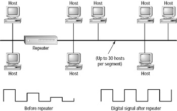
Figure 1.1: Repeater in a LAN
Sometimes repeaters are placed between the source and destination hosts to help compensate for signal deterioration due to attenuation. This results in latency—a delay in the time it takes the signal to travel between the source and destination hosts.
Bridges
Bridges also regenerate signals, but they are more intelligent devices than repeaters. A bridge can read the destination MAC (Media Access Control) address or hardware address from the data frame and determine if the destination computer is on the local segment—the segment from which it received the frame—or on other network segments. If the destination computer is on the local segment, it won’t forward the frame. If the destination computer isn’t on the local segment, the bridge will forward the frame to all other network segments. Figure 1.2 shows how a bridge in a LAN works.
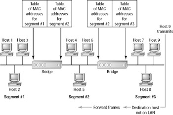
Figure 1.2: Bridging a LAN
When segmenting an Ethernet LAN, using a bridge instead of a repeater can give you more bandwidth per user because it translates into fewer users per segment. But again, you can end up experiencing latency problems of up to 20–30 percent due to processing and filtering frames. Also, since bridges forward broadcasts to all other attached segments, broadcast storms can result from the broadcast packets propagating throughout the network. A broadcast storm is a network segment event; during one, a broadcast packet is sent in a perpetual loop until that segment becomes overloaded.
Hubs
Hubs connect all computer LAN connections into one device or concentrator. Hubs can be considered multiport repeaters. PCs can be connected using coax or twisted-pair cable, or even radio frequency (RF). When one computer transmits a digital signal onto the network media, the signal is transmitted to all other segments that are plugged into the hub. Figure 1.3 shows a typical hub working in a LAN.
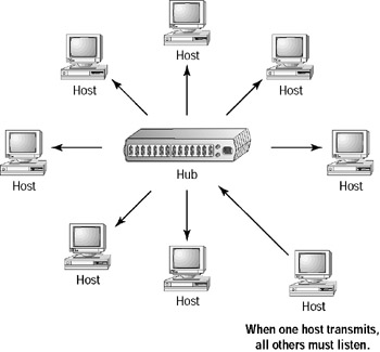
Figure 1.3: LAN connections in a hub
Switches
Unlike hubs, switches can run in full-duplex mode. This means that the computer and switch can both transmit and receive simultaneously. The biggest difference between a switch and a hub is that when a computer transmits a digital signal to a hub, it’s then sent to all ports attached to that hub, whereas a switch will send it only to the specific port where the destination MAC address is located. Think of each switch port as being an extremely fast multi-port bridge.
Routers
Routers are a step up from bridges. Bridges filter by MAC address, but routers can filter by both hardware and network address (IP address). Repeaters operate at layer 1, bridges and switches layer 2, and routers layer 3 of the OSI reference model, which I will cover at length later in this chapter. When a bridge forwards a packet, it sends it out to all segments to which it is connected, whereas a router only forwards packets to the network segment that the packet is destined for. Routers economically prevent unnecessary network traffic from being sent over the network’s segments by opening up the data packet and reading the network address before forwarding it. Figure 1.4 shows a typical LAN with a router segmenting the network.
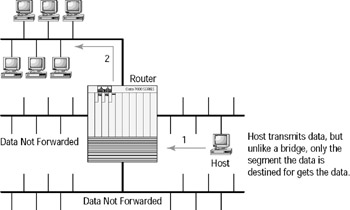
Figure 1.4: A router segmenting a LAN
Gateways
Gateways are created with software that can be run on PCs and even routers. They link different programs or protocols and examine the entire packet, including the data portion, in order to translate incompatible protocols. For example, to exchange mail between a CCMail server and an Exchange server, you would have to install a mail gateway. Another example would be gateway services that run on a router. These can link an IP network to an IPX network so the users on the IP network can communicate transparently with the users on the IPX network and vice versa.
ATM Switches
ATM (Asynchronous Transfer Mode) switches provide high-speed cell switching. ATM uses a cell relay technology that combines the advantages of both conventional circuit and packet-based systems.
WAN Devices
WANs extend beyond the LAN to connect together networks located in different buildings, cities, states, and countries. WANs are typically, but not necessarily, limited to using the services of Regional Bell Operating Companies (RBOCs) like Pacific Bell, AT&T, Sprint, MCI, and others. Figure 1.5 shows a WAN connecting offices in three cities.
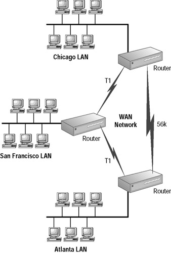
Figure 1.5: Routers connecting three cities creating a WAN
WANs are connected over links that operate at lower speeds than LANs. Typical WAN devices include
Routers In the WAN environment, routers offer both internetworking and WAN interface controls.
ATM switches ATM switches provide high-speed cell switching between both LANs and WANs.
X.25 and Frame Relay switches X.25 and Frame Relay switches connect private data over public data circuits using digital signals.
Modems Modems connect private data over public telephone circuits using analog signals.
CSUs/DSUs Components of customer premises equipment (CPE), channel service units (CSUs), and data service units (DSUs) are used to terminate a digital circuit at the customer site. These connect to a central office (CO), which is the telephone company switch located closest to the customer.
Communication servers Communication servers are typically dial-in/ dial-out servers that allow users to dial in from remote locations and attach to the LAN. Cisco’s AS5300 series of communication servers are an example of devices that provide such services.
Multiplexors Multiplexors are devices that allow more than one signal to be sent out simultaneously over one physical circuit. The equipment is usually referred to as a mux.
|
EAN: 2147483647
Pages: 201