TCPIP
|
TCP/IP
Remember our discussion in Chapter 1 covering the OSI model? Well, the DOD model, upon which TCP/IP is based, is a condensed version of the OSI model. It comprises four, instead of seven, layers:
-
Process/Application
-
Host-to-Host
-
Internet
-
Network Access
Figure 3.1 compares the four-layer DOD model and the seven-layer OSI reference model. As you can see, the two are similar in concept, but each has a different number of layers with different names.
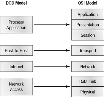
Figure 3.1: The DOD model and the OSI model
If you were to set the DOD and OSI models side-by-side, here is a snapshot of how their layers would compare. We’ll discuss each in more detail as we move through the chapter.
Multiple protocols at the DOD model’s Process/Application layer perform the functions described at the OSI model’s corresponding top three layers (Session, Presentation, and Application). The Process/Application layer defines protocols for node-to-node application communication and controls user interface specifications.
The Host-to-Host layer parallels the functions of the OSI model’s Transport layer, defining protocols for setting up the level of transmission service for applications. It tackles issues like creating reliable end-to-end communication and ensuring the error-free delivery of data. It handles packet sequencing and maintains data integrity.
The Internet layer corresponds to the OSI model’s Network layer, designating the protocols relating to the logical transmission of packets over the entire network. It takes care of the addressing of hosts by giving them an IP (Internet Protocol) address and handles the routing of packets among multiple networks. It also controls the communication flow between two hosts.
At the bottom of the DOD model, the Network Access layer monitors the data exchange between the host and the network. The equivalent of the Data Link and Physical layers of the OSI model, the Network Access layer oversees hardware addressing and defines protocols for the physical transmission of data.
While the DOD and OSI models are alike in design and concept and have similar functions in similar places, how those functions occur are different. This difference requires the DOD model to have a very different suite of protocols than those of the OSI model. Figure 3.2 shows the TCP/IP protocol suite and how its protocols relate to the DOD model layers.
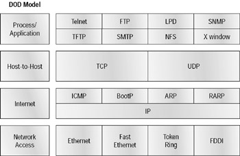
Figure 3.2: The TCP/IP protocol suite
Process/Application Layer Protocols
As discussed earlier in this book, one of the design goals of the creators of the Internet was to have applications that could run on different computer platforms, in different places, and yet, somehow, still communicate. A great goal—but difficult to execute because of the sheer number of manufacturers and their designers’ and engineers’ preferences. In the DOD model, the answer came in the form of Process/Application layer protocols, which address the ability of one application to communicate with another, regardless of hardware platform, operating system, and other features of the two hosts.
Most applications written with TCP/IP protocols can be characterized as client/server applications. This means that there are two major parts to the software involved and that they are probably running on at least two different machines.
The server part of this software duo usually runs on the machine where the data actually resides. The server tends to be powerful (or should be), because much of the data processing and storage is done on it. It works like this: The client software sends requests to the server software for it to fulfill. Typical requests might include searches for information, printing, e-mailing, application services, and file transfers.
In addition to communicating with the server, another function of client software is to provide an interface for the user(s) with the information they need. It also permits these users to manipulate the data they’ve received from the server.
These matters explained, let’s move along and investigate the types of protocols that populate the DOD model’s Process/Application layer and what they do.
Telnet
The chameleon of protocols, Telnet’s specialty is terminal emulation. It allows a user on a remote client machine, called the Telnet client, to access the resources of another machine, the Telnet server. Telnet achieves this by pulling a fast one on the Telnet server and making the client machine appear as though it were a terminal directly attached to the local network. This projection is actually a software image, a virtual terminal that can interact with the chosen remote host. These emulated text-mode terminals can execute refined procedures like displaying menus that allow users to choose options from them and thereby access the applications on the duped server. Users begin a Telnet session by running the Telnet client software and then logging on to the Telnet server.
Telnet’s capabilities are limited to running applications or snooping around on the server like a telescope on a submarine. It can’t be used for file- sharing functions like downloading information. To actually get the goods, you have to use the next protocol on the list: FTP.
FTP (File Transfer Protocol)
The File Transfer Protocol (FTP) is the protocol that actually lets you transfer files; it can facilitate file transfer between any two machines running TCP/IP. But FTP isn’t just a protocol—it’s also a program. Operating as a protocol, FTP is used by applications. As a program, it is employed by users to perform file tasks by hand. FTP allows access to directories and files and permits certain directory operations, such as relocating into different directories. FTP teams up with Telnet to transparently log you in to the FTP server and then provides for the transfer of files.
When accessing a host through FTP, users must contend with an authentication login secured with passwords and usernames and designed by system administrators to restrict access. You might succeed in gaining access by adopting the username “anonymous,” but once in, your access likely will be limited. System administrators rely on their users to choose hard-to-guess passwords to keep out hackers.
Even when being employed by users manually as a program, FTP’s functions are limited to listing and manipulating directories, typing file contents, and copying files between hosts. It can’t execute remote files as programs.
SMTP (Simple Mail Transfer Protocol)
The Simple Mail Transfer Protocol (SMTP), commonly used to transfer e-mail, employs a spooled (queued) method of mail delivery. Once a message has been sent to a destination, the message is spooled to a device—usually a disk. The server software at the destination posts a vigil, regularly checking this queue for messages. When it detects messages, it delivers them to their destination.
LPD (Line Printer Daemon)
The Line Printer Daemon (LPD) protocol is designed for printer sharing. The LPD daemon, along with the LPR (Line Printer) program, allows print jobs to be spooled and sent to the network’s printers.
X Window
Designed for client/server operations, X Window defines a protocol for the writing of graphical user interface (GUI) based client/server applications. The idea is to allow a program (the client) to run on one computer and display a program (a window server) on another computer.
Host-to-Host Layer Protocols
The Host-to-Host layer’s main purpose is to shield the upper layer applications from the complexities of the network and functions like the Transport layer in the OSI model. In fact, the term “Transport layer” is often used interchangeably with Host-to-Host. This layer says to the upper layer, “Just give me your data, with any instructions, and I’ll begin the process of getting your information ready for sending.” The following sections describe the two main protocols at this layer.
TCP (Transmission Control Protocol)
In elementary school we had “safety monitors” on every floor who watched the hallways for violators during recess and lunch. They had a set of rules and limited authority. For instance, they could send you back to your room to walk the distance again if they caught you running. If your infraction was severe, they reported you to a teacher or even the principal. I tried everything to break the rules without getting caught (kind of like a hacker). Yet they did preserve a kind of order in what could be a chaotic environment.
TCP’s role is something like a hall monitor. TCP has been around since networking’s early years, when WANs weren’t very reliable. It was created to mitigate that problem, so reliability is TCP’s strong point. It tests for errors, resends data if necessary, and reports the occurrence of an error to the upper layers if it can’t solve the problem itself.
Did you see the same TV documentary I did about the process of moving the famous London Bridge to Havasu City, Nevada? Engineers numbered, disassembled, transported, and reassembled bridge pieces in sequence. Voila! Instant tourist attraction (that I hope doesn’t become a Stonehenge that messes up the minds of archeologists in future millennia).
Like the London Bridge move, TCP takes large blocks of information from an application and breaks them down into segments. It numbers and sequences each segment so that the destination’s TCP protocol on the receiving end can put the segments back into the order that the application intended. Unlike the bridge process, after these segments have been sent, TCP waits for acknowledgment for each one from the receiving end’s TCP, retransmitting the ones that haven’t been acknowledged.
Before it starts to send segments down the model, the sender’s TCP protocol contacts the destination’s TCP protocol in order to establish a connection. What is created is known as a virtual circuit. This type of communication is called connection-oriented. During this initial handshake, the two TCP layers also agree on the amount of information that’s going to be sent before the recipient’s TCP sends back an acknowledgment. With everything agreed upon in advance, the path is paved for reliable Application layer communication to take place.
TCP is a full-duplex, connection-oriented, reliable, accurate protocol, and establishing all these terms and conditions, in addition to checking for errors, is no small task. It’s very complicated and, not surprisingly, very costly in terms of network overhead. TCP should be used in situations when reliability is of utmost importance.
UDP (User Datagram Protocol)
The User Datagram Protocol (UDP) can be used in place of TCP. UDP is the scaled-down economy model, and is considered a thin protocol. Like a thin person on a park bench, UDP doesn’t take up a lot of room—in this case, on a network. It also doesn’t offer all the bells and whistles of TCP, but it does do a fabulous job of transporting information that doesn’t require reliable delivery—and it does it using far fewer network resources. (Please note that UDP is covered thoroughly in RFC 768.)
Some situations definitely call for UDP rather than TCP; for instance, when the matter of reliability is already accomplished at the Process/Application layer. Network File System (NFS) handles its own reliability issues, making the use of TCP both impractical and redundant. However, this is decided by the application developer, not by the user who wants to transfer data faster.
UDP receives upper layer blocks of information, instead of streams of data like TCP, and breaks them into segments. Also like TCP, each segment is given a number for reassembly into the intended block at the destination. However, UDP does not sequence the segments and does not care in which order the segments arrive at the destination. At least it numbers them. But after that, UDP sends them off and forgets about them. It doesn’t follow through, check up on, or even allow for an acknowledgment of safe arrival—complete abandonment. Because of this, it’s referred to as an unreliable protocol. This does not mean that UDP is ineffective, only that it doesn’t handle issues of reliability.
There are more things UDP doesn’t do. It doesn’t create a virtual circuit, and it doesn’t contact the destination before delivering information to it. It is therefore also considered a connectionless protocol.
Key Concepts of Host-to-Host Protocols
Table 3.1 highlights some of the key concepts that you should keep in mind regarding these two protocols.
| TCP | UDP |
|---|---|
| Virtual circuit | Unsequenced |
| Sequenced | Unreliable |
| Acknowledgments | Connectionless |
| Reliable | Low overhead |
Connection-Oriented and Connectionless Network Services
This chapter has covered both connection-oriented and connectionless network services in the Transport layer (OSI model) and in the Host-to- Host layer (DOD model). A telephone analogy might help you understand how TCP works. Most of you know that before you speak with someone on a phone, you must first establish a connection with that other person— wherever they might be. This is like a virtual circuit with the TCP protocol. If you were giving someone important information during your conversation, you might ask, “Did you get that?” A query like that is similar to a TCP acknowledgment. From time to time, for various reasons, people also ask, “Are you still there?” They end their conversations with a “goodbye” of some kind, putting closure on the phone call. These types of functions are also done by TCP.
Using UDP, however, is more like sending a postcard. To do that, you don’t need to contact the other party first. You simply write your message, address it, and mail it. This is analogous to UDP’s connectionless orientation. Since the message on the postcard is probably not urgent, you don’t need an acknowledgment of its receipt. Similarly, UDP does not involve acknowledgments.
Internet Layer Protocols
There are two main reasons for the Internet layer’s existence: routing and providing a single network interface to the upper layers. None of the upper layer protocols, and none of those on the lower layer, have any functions relating to routing. The complex and important task of routing is the job of the Internet layer. IP (Internet Protocol) essentially is the Internet layer. The other protocols found here merely exist to support it. IP contains the “Big Picture” (city map) and could be said to “see all,” in that it is aware of all the interconnected networks (roadways). It can do this because all the machines on the network have a software (logical) address called an IP address, which is described more thoroughly later in this chapter.
IP looks at each packet’s IP address. Then, using a routing table, it decides where a packet is to be sent next, choosing the best path. The Network Access layer protocols at the bottom of the DOD model don’t possess IP’s enlightened scope of the entire network; they deal only with physical links.
The second reason for the Internet layer is to provide a single network interface to the upper layer protocols. Without this layer, application programmers would need to write “hooks” into every one of their applications for each different Network Access protocol. This would not only be tedious, it would lead to different versions of each application—one for Ethernet, another one for Token Ring, and so on. To prevent this, IP provides one single network interface for the upper layer protocols. That accomplished, it’s then the job of IP and the various Network Access protocols to get along and work together.
All network roads don’t lead to Rome—they lead to IP. And all the other protocols at this layer, as well as all those at the upper layers, use it. Never forget that. All paths through the DOD model go through IP. The following sections describe the protocols at the Internet layer.
IP (Internet Protocol)
Identifying devices on networks requires answering these two questions:
-
Which network is it on?
-
What is its ID on that network?
The first answer is the software, or logical address (the correct street). The second answer is the hardware address (the correct mailbox). All hosts on a network have a logical ID called an IP address. This is the software, or logical, address and it contains valuable encoded information that greatly simplifies the complex task of routing. (Please note that IP is discussed in RFC 791.)
IP receives segments from the Host-to-Host layer and fragments them into datagrams (packets). IP also reassembles datagrams back into segments on the receiving side. Each datagram is assigned the IP address of the sender and the IP address of the recipient. Each machine that receives a datagram makes routing decisions based upon the datagram’s destination IP address.
ARP (Address Resolution Protocol)
When IP has a datagram to send, it has already been informed by upper layer protocols of the destination’s IP address. However, IP must also inform a Network Access protocol, such as Ethernet or Token Ring, of the destination’s hardware address. If IP doesn’t know the hardware address, it uses the Address Resolution Protocol (ARP) to find this information. As IP’s detective, ARP interrogates the network by sending out a broadcast asking the machine with the specified IP address to reply with its hardware address. In other words, ARP translates the software (IP) address into a hardware address— for example, the destination machine’s Ethernet board address—and from it, deduces its whereabouts.
This hardware address is technically referred to as the media access control (MAC) address or physical address. ARP is talked about in detail in the section “IP Address Resolution” later in this chapter.
RARP (Reverse Address Resolution Protocol)
When an IP machine happens to be a diskless machine (like a printer), it has no way of initially knowing its IP address, but it does know its MAC address. The Reverse Address Resolution Protocol (RARP) discovers the identity of these machines by sending out a packet that includes its MAC address and a request to be informed of what IP address is assigned to that MAC address. A designated machine, called a RARP server, responds with the answer, and the identity crisis is over. RARP uses the information it does know about the machine’s MAC address to learn its IP address and complete the machine’s ID portrait.
Network Access Layer Protocols
Programmers for the DOD model didn’t define protocols for the Network Access layer; instead, their focus began at the Internet layer. In fact, this is exactly the quality that makes this model easy to implement on almost any hardware platform. This versatility is also one of the reasons the Internet protocol suite is so popular. Every protocol listed here relates to the physical transmission of data. The following are the Network Access layer’s main duties:
-
Receiving an IP datagram and framing it into a stream of bits—1s and 0s—for physical transmission. (The information at this layer is called a frame.) An example of a protocol that works at this level is CSMA/CD (Carrier Sense, Multiple Access with Collision Detection). Again, the protocol’s name indicates its purpose. It checks the cable to see if there’s already another PC transmitting (Carrier Sense), allows all computers to share the same bandwidth (Multiple Access), and detects and retransmits collisions (Collision Detection). Essentially, it’s the highway patrol of the Network Access layer.
-
Specifying the MAC address. Even though the Internet layer determines the destination MAC address, it’s the Network Access protocols that actually place the MAC address into the MAC frame.
-
Ensuring that the stream of bits making up the frame has been accurately received by calculating a CRC (cyclic redundancy checksum).
-
Specifying the access methods to the physical network, such as contention-based for Ethernet (first come, first served), token passing (wait for token before transmitting) for Token Ring and FDDI, and polling (wait to be asked) for IBM mainframes.
-
Specifying the physical media, connectors, electrical signaling, and timing rules.
Physical and Logical Addressing
It’s important to understand the difference between physical and logical addressing. The names appear to say the same thing, but they don’t. The following discussion will help you differentiate between them.
Data Link layer addressing, or physical (hardware) addressing, describes a unique address that is burned into each network interface card (NIC) by the manufacturer. Think of the hardware address like the address to your house. It must be different from the other addresses or your mail just isn’t going to get to you. The hardware address is a 48-bit address expressed as 6 bytes, as shown in Figure 3.3. The first 3 bytes, known as the vendor code, are given to the manufacturer by the IEEE. The IEEE administers this Organizational Unique Identifier (OUI) so there aren’t any duplicate hardware addresses floating around. The second 3 bytes are made up by the manufacturer and are generally part of the serial number of the card.
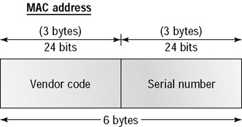
Figure 3.3: MAC addresses
Logical addressing, sometimes referred to as virtual addressing, is used at the Network layer and is hierarchical in scheme, unlike physical addresses, which use a flat addressing scheme. The logical address defines more than the house on a street. The logical address can define the country, state, zip code, city, street, street address, and even the name. Examples of protocols that use logical addresses are IP and IPX.
Some of the technologies used to implement the Network Access layer are
-
LAN-oriented protocols
-
Ethernet (thick coaxial cable, thin coaxial cable, twisted-pair cable)
-
Fast Ethernet
-
Token Ring
-
-
WAN-oriented protocols
-
Point-to-Point Protocol (PPP)
-
X.25
-
Frame Relay
-
|
EAN: 2147483647
Pages: 201