Introduction to Virtual LANs (VLANs)
|
You’ve seen virtual local area networks (VLANs) mentioned several times in this chapter already. At long last, this section discusses them in detail. As you can see from Figure 2.11, Layer 2 switched networks are typically designed as flat networks. Every broadcast packet transmitted is seen by every device on the network, regardless of whether the device needs to receive that data or not.
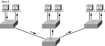
Figure 2.11: Flat network structure
By default, routers allow broadcasts only within the originating network, but switches forward broadcasts to all segments. The reason it’s called a flat network is because it’s one broadcast domain, not because its design is physically flat.
Notice in Figure 2.11 that Host A is sending a broadcast and all ports on all switches are forwarding this broadcast, except for the port that originally received it. Now look at Figure 2.12, which pictures a switched network. It shows Host A sending a frame with Host D as its destination, and as you can see, that frame is only forwarded out the port where Host D is located. This is a huge improvement over the old hub networks, unless having one collision domain by default is what you really want.
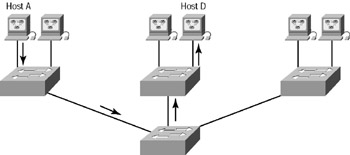
Figure 2.12: The advantage of a switched network
Now you already know that the largest advantage gained by having a Layer 2 switched network is that it creates individual collision domain segments for each device plugged into the switch. This scenario frees you from the Ethernet distance constraints, so now larger networks can be built. But with each new advance, you often encounter new issues—the larger the number of users and devices, the more broadcasts and packets each switch must handle!
And there’s another benefit of VLANs—security! In the typical Layer 2 switched internetwork, all users can see all devices by default. And you can’t stop devices from broadcasting, nor can you stop users from trying to respond to broadcasts. Your security options are dismally limited to placing passwords on the servers and other devices.
But not if you create VLANs, my friend! Yes, indeed, you can solve many of the problems associated with Layer 2 switching with VLANs—as you’ll soon see.
There are several ways that VLANs simplify network management:
-
The VLAN can group several broadcast domains into multiple logical subnets.
-
Network adds, moves, and changes are achieved by configuring a port into the appropriate VLAN.
-
A group of users needing high security can be put into a VLAN so that no users outside of the VLAN can communicate with them.
-
As a logical grouping of users by function, VLANs can be considered independent from their physical or geographic locations.
-
VLANs can enhance network security.
-
VLANs increase the number of broadcast domains while decreasing their size.
Broadcast Control
Broadcasts occur in every protocol, but how often they occur depends upon three factors:
-
The type of protocol
-
The application(s) running on the internetwork
-
How these services are used
Some older applications have been rewritten to reduce their bandwidth needs, but there’s a new generation of applications that are incredibly bandwidth-greedy, consuming all they can find. These bandwidth abusers are multimedia applications that use broadcasts and multicasts extensively. And faulty equipment, inadequate segmentation, and poorly designed firewalls only serve to compound the problems that these broadcast-intensive applications create. All of this has truly added a new dimension to network design, while generating new challenges for a network administrator. Making sure the network is properly segmented in order to isolate one segment’s problems and keeping those problems from propagating throughout the internetwork is imperative. The most effective way of doing this is through strategic switching and routing.
Since switches have become more cost-effective lately, many companies are replacing their flat hub networks with a pure switched network and VLAN environment. All devices in a VLAN are members of the same broadcast domain and receive all broadcasts. The broadcasts, by default, are filtered from all ports on a switch that are not members of the same VLAN. This is great because it offers all the benefits you gain with a switched design without the serious anguish you would experience if all your users were in the same broadcast domain!
Security
But there’s always a catch, so let’s get back to those security issues. A flat internetwork’s security used to be tackled by connecting hubs and switches together with routers. So it was basically the router’s job to maintain security. This arrangement was pretty ineffective for several reasons. First, anyone connecting to the physical network could access the network resources located on that physical LAN. Second, all anyone had to do to observe any and all traffic happening in that network was to simply plug a network analyzer into the hub. And in that same vein, users could join a workgroup by just plugging their workstations into the existing hub. So basically, this was non-security!
This is why VLANs are so cool. By building them and creating multiple broadcast groups, administrators can now have control over each port and user! The days when users could just plug their workstations into any switch port and gain access to network resources are history, because the administrator is now awarded control over each port and whatever resources that port can access.
Also, because VLANs can be created in accordance with the network resources a user requires, switches can be configured to inform a network management station of any unauthorized access to network resources. And if you need inter-VLAN communication, you can implement restrictions on a router to achieve it. You can also place restrictions on hardware addresses, protocols, and applications—now you’re talking security!
Flexibility and Scalability
If you’re paying attention to what you’ve read so far, you know that Layer 2 switches only read frames for filtering—they don’t look at the Network layer protocol. And by default, switches forward all broadcasts. But if you create and implement VLANs, you’re essentially creating smaller broadcast domains at Layer 2.
This means that broadcasts sent out from a node in one VLAN won’t be forwarded to ports configured to be in a different VLAN. So by assigning switch ports or users to VLAN groups on a switch or group of connected switches (called a switch fabric), you gain the flexibility to add only the users you want into that broadcast domain regardless of their physical location! This setup can also work to block broadcast storms caused by a faulty network interface card (NIC) and prevent an application from propagating the storms throughout the entire internetwork. Those evils can still happen on the VLAN where the problem originated, but the disease is just quarantined to that one ailing VLAN.
Another advantage is that when a VLAN gets too big, you can create more VLANs to keep the broadcasts from consuming too much bandwidth—the fewer users in a VLAN, the fewer users affected by broadcasts. This is well and good, but you absolutely need to keep network services in mind and understand how the users connect to these services when you create your VLAN. It’s a good move to try and keep all services—except for the e-mail and Internet access that everyone needs—local to all users whenever possible.
To understand how a VLAN looks to a switch, it’s helpful to begin by first looking at a traditional network. Figure 2.13 shows how a network was created by connecting physical LANs using hubs to a router.
In Figure 2.13, you can see that each network was attached with a hub port to the router. (Each segment also had its own logical network number, though this is not obvious from the figure.) Each node attached to a particular physical network had to match that network number in order to be able to communicate on the internetwork. Notice that each department had its own LAN, so if you needed to add new users to Sales, for example, you would just plug them into the Sales LAN, and they would automatically be part of the Sales collision and broadcast domain. This design really worked well for many years.
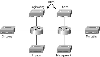
Figure 2.13: Physical LANs connected to a router in a traditional network
But this design has one major flaw: What happens if the hub for Sales is full and you need to add another user to the Sales LAN? Or, what do you do if there’s no more physical space in the location where the Sales team is located for this new employee? Well, let’s say there just happens to be plenty of room in the Finance section of the building. That new Sales team member will just have to sit on the same side of the building as the Finance people, and you’ll just plug the poor soul into the hub for Finance.
Doing this obviously makes that the new user part of the Finance LAN, which is bad for many reasons. First and foremost, you now have a security issue because this new user is a member of the Finance broadcast domain and can therefore see all the same servers and network services that all of the Finance folks can. Second, for this user to access the Sales network services he or she needs to get the job done, they would need to go through the router to log in to the Sales server—not exactly efficient!
Now let’s look at what a switch accomplishes. Figure 2.14 demonstrates how switches remove the physical boundary to solve this problem.
Figure 2.14 shows how six VLANs (numbered 2 through 7) are used to create a broadcast domain for each department. Each switch port is then administratively assigned a VLAN membership, depending on the host and which broadcast domain it must be in.
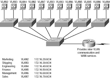
Figure 2.14: Switches removing the physical boundary
So now, if you need to add another user to the Sales VLAN (VLAN 7), you can just assign the port needed to VLAN 7, regardless of where the new Sales team member is physically located—nice! This illustrates one of the sweetest advantages to designing your network with VLANs over the old collapsed backbone design. Now, cleanly and simply, each host that needs to be in the Sales VLAN is merely assigned to VLAN 7.
Notice that the VLAN numbers start with VLAN number 2. The number is irrelevant, but you might be wondering, what happened to VLAN 1? VLAN 1 is an administrative VLAN, and even though it can be used for a workgroup, Cisco recommends that you use this for administrative purposes only. You can’t delete or change the name of VLAN 1, and by default, all ports on a switch are members of VLAN 1 until you change them.
Each VLAN is considered a broadcast domain, so it must also have its own subnet number, as illustrated in Figure 2.14. And if you’re also using Internetwork Packet Exchange (IPX), then each VLAN must also be assigned its own IPX network number.
Now let’s get back to that “because of switches, you don’t need routers anymore” misconception. In Figure 2.14, notice that there are seven VLANs or broadcast domains, counting VLAN 1. The nodes within each VLAN can communicate with each other, but not with anything in a different VLAN, because the nodes in any given VLAN “think” that they’re actually in a collapsed backbone as in Figure 2.13.
And what handy little tool do you need to enable the hosts in Figure 2.13 to communicate to a node or host on a different network? You guessed it— a router! Those nodes positively need to go through a router—or some other Layer 3 device—just like when they’re configured for VLAN communication (as you can see in Figure 2.14). It’s the same as if you were trying to connect different physical networks. Communication between VLANs must go through a Layer 3 device, so don’t expect routers to disappear any time soon! However, a lot of work can be done with Layer 3 switches, which you’ll learn more about in a minute.
|
EAN: 2147483647
Pages: 201