| This tutorial will employ Maya's new Smooth Proxy option to allow you to make polygonal edits to a simplified object, resulting in easy control over curvy surfaces. This method, called "box modeling" by some, allows you to start with a simple box and build any complex sculpted shape through a series of vertex, face, and edge edits, often extruding or splitting polygons where additional detail is needed. It may seem a little strange at first, but after you've modeled a few characters utilizing this technique, you'll likely find it to be a fast and intuitive method for modeling organic shapes . Before you start modeling your polygonal character, you'll take some steps to simplify the process. Most 3D characters you create are symmetrical, like creatures you find in the real world. Instead of making changes to both sides of a creature, and trying to make those changes perfectly symmetrical, Maya can help you by automatically mirroring each edit on the other side of the character. This method saves time and ensures exact symmetry. If you want to add some slight variations on each side for a more natural appearance, you still canyou simply do it as a last step after finalizing the character's symmetrical attributes. Tutorial: Preparing to Model Before you start, remember that you're still working with Maya as set up at the beginning of the tutorials in Chapter 5, "NURBS Modeling Basics." That is, the user interface is simplified to show only the Command Line and Help Line. Also, if you skipped Chapter 5, you'll need to load the marking menus and hotkeys described there. This chapter's tutorials rely on these improvements to Maya's workflow. This tutorial starts with an empty scene. Confirm that history is active: It's the Construction History button at the right of the Status Line (the one with a scroll icon on it). When it's inactive, a red x appears over the button's scroll icon. -
Start a new project (Hotbox File Projects New). Name the project Creature , click the Use Defaults button to use the default directory, and click the Accept button.  -
Set your layout to the standard Four View mode (Hotbox Panels Saved Layouts Four View). -
Start off by creating a polygon cube (Ctrl+x LMB-hold Cube) with the default name of pCube1. -
With the cube still selected, choose Hotbox Polygons Smooth Proxy Option Box. Reset the settings and click the Smooth button to apply the Smooth Proxy and dismiss the dialog. A sphere-like object is apparent in your scene, nested within the cube. Display the Channel Box with layers, and you can see the two layers created by the operation. The smooth layer has an "R" in the display type, indicating that it is a reference layerit cannot be edited, but is modified by another object. That other object is the original cube, which is in the pCube1ProxyMesh layer. tip Layers set to Reference mode cannot be selected. You can toggle through the other two modesNormal and Templateby clicking on the R. -
Switch your Perspective view to Shaded mode (hotkey: 5 ), and you can observe that the Smooth Proxy operation has also set the outer object to a semitransparent state, allowing you to see the effect of edits on the outer object to the shape of the inner object. note There are several ways to smooth a polygon shape. This tutorial uses the first method, modifying the geometry by subdividing the polygons. The second method is to globally "relax" the existing geometry to make it smoother, without adding more polygons. This method is beneficial when you want UVs that are easier to work with. The third method is using the Sculpt Polygons Tool, which allows you to interactively "paint" in the smoothness, selectively applying the same approach as in the second method. -
With the original outer cube still selected, click the polysmoothface1 rollout in the Outputs section of the Channel Box. It will roll out to display the smooth settings for the inner object, which currently looks like a crude sphere. Set the divisions to 2 and then 3, and you'll see the inner object increase in detail. Also, disable the "keep border" option by typing 0 and then enter, as shown in Figure 7.1. Return the divisions value to 1. Figure 7.1. The Smooth Proxy option creates the two layers and sets the inner object to a reference layer so that it is not easily editable. 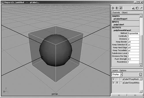 tip Remember to use the Outliner when you're trying to select a particular object in your scene. The Outliner is one of the fastest and most accurate ways to select objects in your scene. Setting Up Cubes for Modeling Often, it's easier to view your models in Shaded mode than in Wireframe mode, but that doesn't mean modeling is more efficient in Shaded mode. The advantage of the Smooth Proxy method you're using is that you have a wireframe "cage" that surrounds a higher-resolution model. You use this simpler low-polygon cube "cage" to create a complex character by intelligently subdividing the controlling mesh cube and pulling on the new points. When modeling a character, it's usually a lot easier to work with just one side of the figure. For that reason, the cubes in these tutorials are set up to have a mirrored version that's automatically updated with the modifications you make to the other side. tip As a general rule, set up orthographic viewports in Wireframe mode (hotkey: 4 ) and Perspective views in Shaded mode (hotkey: 5 ).
Tutorial: Symmetry Made Easy Continue from the previous tutorial or load the scene file listed here. -
Open the Outliner (hotkey: shift+o ), and you'll see the two objects nested into a single groupthis was also created by the Smooth Proxy. Click the "+" to roll out the group and see its members : pCube1 and pCube2. -
Rename the objects by selecting them in the Outliner and renaming them at the top of the Channel Box. Rename pCube1 to cage and pCube2 to smooth, as shown in Figure 7.2.   Figure 7.2. The two objects are now renamed . 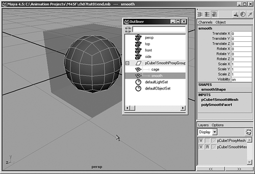 -
To create the character's symmetrical left half, you'll duplicate the cube. First, to move the current geometry to the right to become the right half of the character, select Cage and Smooth, and in the Channel Box, set Translate X to 0.5 . -
Next, you need to open the side of the cube that will meet with the mirrored half by selecting and deleting the polygon faces on the cube's (soon to be) inner side, nearest the scene origin (the 0,0,0 point): To do this, select Cage, RMB-click on Cage, and choose Face. Blue-dot selector handles will appear on the cube's six sides. Select the face on the side that faces the scene origin, and press Delete. The Smooth cube is now open on one side (see Figure 7.3). Press F8 to exit Component mode. Figure 7.3. In the Perspective view, the smoothed cube should now have one side open. 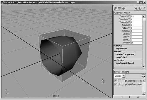 -
The pivot point for the surfaces is offset from the origin, centered between the two objects you've made. Because you want to duplicate the Smooth cube and mirror it, you need to move the pivot point to the location where the objects will be mirrored, so you'll snap the pivot to the 0,0,0 origin. To do that, select Cage in the Outliner, switch to Move mode (hotkey: w ), and press Insert to go to Pivot Editing mode. Then hold down the x key to snap to the grid while dragging the pivot icon in a 3D view with your MMB. Press Insert when finished to exit Pivot Editing mode. Repeat this procedure for the Smooth object. -
Select the Smooth object in the Outliner, and duplicate it (Hotbox Edit Duplicate option box). In the Duplicate Options dialog box, reset the settings, and then set Scale X to 1 and geometry type to instance . Click the Duplicate button. You should now have a duplicate beside your original, with the two visible objects forming a capsule shape. Name the duplicate smoothmirror . You can see the mirrored object in Figure 7.4. Figure 7.4. The Smooth cube now has a mirrored instance for automatic symmetrical adjustment. 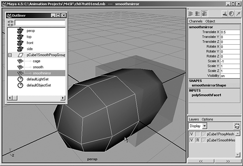 note Test out the new connection by manipulating the Proxy Mesh. To model the Smooth object, you'll adjust the Proxy Mesh, modifying vertices, edges, faces, and so on. Take a moment to play around with the Proxy Mesh to confirm the mirrored instance and see the effect of symmetry. Try selecting the Proxy Mesh and moving some of the vertices. Notice that SmoothMirror reflects the changes made to Smooth, as shown in Figure 7.5. This makes it easy to check your proportions while modeling. Use Undo (hotkey: z ) to put the vertices back to their original position when you are done testing. Figure 7.5. The effect of pulling one of the vertices on your cageSmoothMirror now moves according to the modifications. 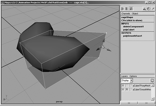 -
Select the SmoothMirror object in the Outliner and assign it to the pCube1-SmoothMesh layer: right-click on the layer name and choose Add Selected Objects. Everything is set now, and you're prepared to model your creature by using the Smooth Proxy polygonal modeling method. Save your scene as SProxySetup . If you get stuck creating the initial setup for the character, you can load the file below the CD icon to get you started.  |


