2.3 Introducing Use Cases, Use Case Diagrams, and Scenarios
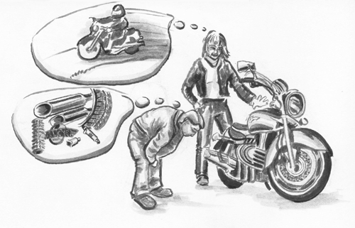
| DEFINITION: A use case represents a series of interactions between an outside entity and the system, which ends by providing business value. Part of our solution to the requirements-gathering problem is to deploy use cases, a deceptively simple tool that examines a computer system by expressing the interactions between the system and its environment: what goes in and what comes out. This sounds simple, but in practice it becomes very difficult. In our experience, systems professionals have an extremely hard time producing use cases that mean anything to the users. Systems people are used to dealing with systems as white boxes, not black boxes, and are focused on the how . Users see only the black box: the what . In the book Zen and the Art of Motorcycle Maintenance , Robert Pirsig (1994) uses historical terms to describe differing views of a motorcycle: the classic view and the romantic view. The classic view sees a motorcycle in terms of its subsystems: power train, braking, steering, safety, and so on. The romantic view sees the motorcycle as what it can do for the rider : speed up, slow down, weave through traffic, avoid accidents, and so forth. Each view sees exactly the same motorcycle, but they see it from much different perspectives. Two people see a motorcycle in two ways: as the subsystems that make up the bike and as the things a person can do with the bike. Use cases in the requirements activity see the system from the romantic view. They are concerned only with what the system can do for the users. This makes them extremely effective for conveying information to users because they cut out all classic viewpoints and boil down the requirements to the barest essentials. To apply use cases effectively to the requirements-gathering process, you need to understand the goals of use cases, which are discussed in the next section. Use cases are simple in structure, but preparing them correctly is difficult. This is often the case with simple representations of complex things. In the following subsections, we explore the notation of the use case and how it fits in with the rest of the UML. 2.3.1 The Goals of Use Cases2.3.1.1 Interactions That Provide Value to ActorsUse cases are meant to show the interactions between the system and the entities external to the system. External entities, or actors, include users, other computer systems, or external events, such as reaching a specific date or time. Each interaction should provide something of value to the external entity. If it does not, it should contribute directly to a value provided to an external entity that does not participate in the interaction. For example, a management information system may not provide value to the clerk who keys in volumes of data, but the data contributes directly to the manager, who uses the data to make business decisions. Similarly, a production accounting system may gather information from a metering system but actually provide the value to another actor, perhaps a general ledger system. When the interaction occurs between the system and an external event such as date/time, the external event does not gain a value from the interaction; nevertheless, some other external entity should benefit from the interaction. 2.3.1.2 No Implementation-Specific LanguageAs mentioned previously, use cases are black-box representations, and this means that use cases do not include any implementation-specific language . As the use case author, you avoid using implementation-specific language by not making any assumptions about how this use case is realized in program code or the user interface. Table 2.1 provides examples of implementation-specific language and our suggestions for improving it. Table 2.1. Removing Implementation-Specific Language
Be careful about using implementation-specific terms in these areas:
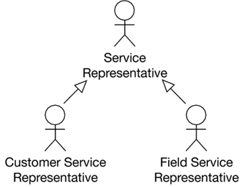
Hand in hand with the rejection of implementation-specific language, use cases should be written in the users' vocabulary. All data items and interactions should be termed and phrased using the same language that the users adopt to describe their jobs. We call use cases that have no implementation references context-free use cases. It means that we can apply these use cases to any context ”technical, implementation, user interface, workflow, and so forth ”and they will still be perfectly applicable . Sometimes, implementation-specific language is OK. Having stated firmly that you should never put implementation-specific details in use cases, now let's discuss when you should do it: when they are being produced or refined outside the boundaries of requirements gathering. Because use cases drive the whole lifecycle, it is reasonable to assume that they are modified throughout the lifecycle. In fact, use cases become increasingly implementation-specific as time goes on, reflecting the work being done at the time. Another term for implementation-specific, in this context, is real . The term real use cases comes from Larry Constantine (1999) and is documented in Craig Larman's book (2002). Any use cases that reflect the requirements view should be saved separately, but they can also become input to use cases that help manage the work of design, construction, testing, and architecture. 2.3.1.3 User-Appropriate Level of DetailAs you proceed through requirements gathering, use cases go from being general to being detailed. As IT professionals, we tend to migrate to the details quickly. It is important to at least start at a general level before jumping to the details. Keep in mind that use cases should always be in the users' vocabulary. This may help you keep to a suitable level of detail. 2.3.1.4 User-Appropriate VolumeAt the Object-Oriented Programming System, Languages, and Applications (OOPSLA) conference in 1996, Ivar Jacobson said that a very large system should have no more than 70 to 80 use cases. He stated that he couldn't imagine a system so large it would require 100 use cases. Sound impossible ? This means that most systems would have perhaps 20 to 50 use cases, and some small systems even fewer. Debbie Ard, a business analyst friend of ours, has decided that every reasonably large application seems to have 28 use cases! That is a great number to shoot for; it is an easy set of use cases to understand and relate to. We have found that if we use good judgment, it is not only possible but also extremely wise to keep the number of use cases very small. In producing such a small number of use cases for functionality so grand, the analysts and users are forced to abstract the activities of the system until they truly represent what the system must accomplish. After the distractions and assumptions are pulled out, two processes that may seem to be unique begin to merge, and a better abstraction results. Please note that we refer to the number of use cases and not the number of scenarios. Scenarios are individual instances of use cases that traverse a specific path using specific data. There can be a large number of scenarios, depending on how detailed the testing effort becomes or how much confusion exists between users and requirements analysts. Remember that each use case represents a fairly abstract interaction between actor and system. The individual paths through the use case, shown in the Alternative Path and Exception Path sections in the use case template (discussed in Section 2.3.3), form the basis for the detailed processing that usually requires volumes of documentation to represent. 2.3.2 How Use Case Diagrams Show RelationshipsUse cases are text documents. To show two kinds of relationships ”those between use cases and those between use cases and actors ”we employ use case diagrams. As with all UML diagrams, use case diagrams have specific rules about notation. The following subsections explain these rules. 2.3.2.1 Actors and RolesDEFINITION: An actor is an outside entity that interacts with the system. Use cases never initiate actions on their own. The initiator of all interactions is the actor: something outside the computer application. Actors can be people, other computer systems, or something more abstract, such as a specific date and time. Actors shown on the use case diagram should be those that interact directly with the system or are influenced directly by the system. The use case actor? It is often hard to decide which actors to show on a use case diagram. For example, when a supplier provides an invoice to a company clerk and the clerk enters the invoice into the system, should the supplier be included in the diagram? If the supplier is shown, it is called a secondary actor. Our rule is that the supplier should be shown in the diagram if the supplier's behavior impacts the system in any way. For example, if a supplier sends a shipment late and that changes how the system reacts, then the supplier should be in the diagram. Other computer systems can also be actors. For example, when your system feeds postings to a general ledger system, that general ledger system becomes an actor in your use case diagram. Similarly, if other systems feed your system, they should also appear in your diagrams. A trigger of some sort can also be an actor. For example, if a system goes into action when a certain date or time is reached, such as 7:00 PM on the last workday of the month, then the date/time becomes the actor. Similarly, if a system is initiated by a condition of its environment, such as the pressure in a natural gas pipeline increasing above a certain level, then the pressure in the pipeline becomes the actor. However, the system in scope for your project can never be an actor. If actors are outside the boundaries of your system, by definition, the system you are building cannot be outside the scope! Actors are external to the system and outside its responsibility. It might be helpful to treat each actor as an assumption . You assume that the actor is out of scope and that the system will interact with it but not automate it. Actors can be treated as use cases when analysts begin looking at the use cases to start building an object model. Actors may influence how the classes are constructed ; in fact, they themselves may become classes. Therefore, it makes sense to take care in creating the right actor to interact with the use cases. (We talk about how actors in use cases influence security in Chapter 8.) Interactions between actors and use cases are shown with a straight, unbroken line with no arrows. It is not customary to label these lines. The description of what is behind these lines is what constitutes the Basic Course of Events section in the use case text. Good actor names are quite specific but are not linked to organizational positions or certain users. When to Show Secondary ActorsYou should show secondary actors on use case diagrams when the specific actions of the secondary actor have an effect on the responses the application provides. Another rule of thumb is to make early judgments about whether the data regarding this secondary actor will be stored in the system in any way. Role NamesYou may notice that there are names at the actor ends of the arrows in the use case diagram examples. These are role names . Role names are useful when the association between an actor and a use case needs information beyond the fact that they interact. In this example, these associations are special because the actors are only observers . This role must be defined according to its implications. Perhaps they have read-only access to some data. This information is captured now, at requirements time, and is useful later in design. 2.3.2.2 AssociationsAssociations can exist between an actor and a use case, between use cases, and between actors. Let's examine each type of association. GeneralizationGeneralization is a concept that is borrowed from the object-oriented world. When several use cases, for example, have something in common that can be abstracted into another, higher-level use case, they are said to be generalized. Figure 2.11 shows two subactors being generalized into a superactor . Two types of representatives ”customer and field ”have behavior or attributes in common that are described under the service representative superactor. This type of generalization of actors should be done for one of two reasons.
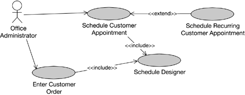
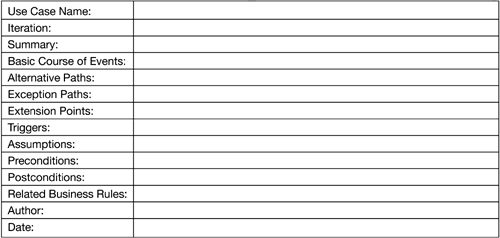
Figure 2.11. Customer and Field Representative Generalized as Service Representative The superactor should interact with use cases when all its subactors interact the same way with use cases. The subactors should interact with use cases when their individual interactions differ from that of the superactor. Use cases can also be generalized using the same notation, but it is not used very often. We usually create one use case diagram that contains nothing but the actor generalizations . ExtendUse case associations stereotyped as <<extend>> indicate a relationship in which a special use case (the blunt side of the association) extends an original use case (the sharp side of the association). This is useful when certain special cases would clutter up the original use case. In Figure 2.12, the use case Schedule Recurring Customer Appointment extends the functionality of Schedule Customer Appointment . This means that it changes the interaction with the actor in some tangible way that would be cumbersome to include in the original use cases. For example, the actor might need to input the number of recurring appointments or the date that appointments should stop recurring. This particular interaction would not occur in the original use case. Figure 2.12. Include and Extend Notation The extending use case (the blunt side of the arrow) is the special case of the extended use case (the sharp side of the arrow), and therefore the extending use case would not exist without the extended use case. IncludeThe <<include>> association stereotype allows use case designers to avoid duplicating steps across multiple use cases. You deploy it as a reuse strategy for use case text instead of cutting and pasting steps into multiple use case documents. In Figure 2.12, Enter Costume Order, Schedule Customer Appointment , and Enter Uniform Order have some similar steps, which can be drawn out into a separate use case called Schedule Designer . There may be other pieces of these use cases that are common, and they, too, could become separate use cases with include associations back to the owning use cases. Our frank advice about <<extend>> and <<include>> is this: don't use them. There are almost always ways to avoid using them, and the dangers of using them are so great that it is best to stay away. One instance where << extend>> or << include>> may be appropriate is where the use cases of an initial release of a product must be enhanced for a second release, and therefore the original use cases may be extended to add the new functionality. 2.3.3 The Use Case TemplateMost of the UML elements are diagrams. A use case is actually a page or two of text representing each oval in the use case diagram. You need a common template for use cases in a project. Figure 2.13 presents a sample template. Standardization on a template is more important than what the template itself looks like. You can use our template or the template supplied with the RUP. Or, best of all, you can create your own template that uniquely addresses the requirements of your organization. It is helpful, however, if the same template is used for all projects within an organization. We have these rules for creating good-quality templates.
Figure 2.13. A Sample Use Case Template 2.3.3.1 Use Case NameThe use case name provides a unique identification. We prefer a unique identifier that is written in English. Long ID numbers tend to turn off users. 2.3.3.2 IterationIteration relates to each of the three stages through which we see use cases progressing: Facade, Filled, and Focused (see Section 3.3). Each use case progresses through these iterations at its own pace. 2.3.3.3 SummaryIn one or two sentences, describe the interaction that occurs in this use case. Try not to regurgitate the basic course of events. Remember that each section should add its own unique value. The summary section may provide some context that other sections don't contain. 2.3.3.4 Basic Course of EventsThis is the meat of the use case. Describe the steps that the actors and the system go through to accomplish the goal of this use case. The actor always takes the first step, and then the system responds. This goes back and forth until the goal has been accomplished, with some value being provided to the actor. The basic course of events represents the "simple, correct path" through the use case. This means that no errors or missteps occur, either by the actor or the system. It also means that it shows the most common path taken. For example, a retailer may find that 80 percent of all orders use purchase orders (POs), with only occasional cash, check, or credit card use. This means that the basic course of events should show the details of a PO without concern for the other types of payment. Sometimes, courses of events are shown with separate columns for the actor's actions and the system's actions. This arrangement helps to show the interaction that occurs. However, it also makes the use case confusing if more than one actor is involved, something that may happen in some specialized cases (for details, see Section 2.3.2.1). Although we state that use cases are text and not diagrams, we'd like to hedge that definition slightly. The structure, or template, of the use case is text. However, if some kind of picture helps the understanding of a use case, it should be included or attached to the use case. For example, it's quite acceptable to include a price schedule in table format. Furthermore, pictures of decision trees, calculations, flowcharts, or Petri nets are also quite acceptable either inside the use case or as attachments. Again, let the users' perspectives be your guide. If the users will understand the use case better with the pictures, include them. 2.3.3.5 Alternative PathsThe Alternative Paths section shows the less-common paths that need to be addressed. They include situations in which unusual types of processing occur. An alternative path would be taken when an uncommon condition occurs, such as the cash, check, or credit card payment mentioned previously. A single use case often includes several types of alternatives. For example, the Enter Sale use case, which has different types of payment, may also contain alternatives relating to the type of customer, whether industrial or consumer. An industrial customer might have a standing account to which orders are collected and billed monthly, whereas walk-in consumer business is conducted with cash or credit card. Each alternative should indicate which step, in the basic course of events, is its starting point. Alternative paths listed separately from a basic course of events allow you to avoid IF-THEN-ELSE structures. Users usually do not understand programming structures of any kind: IF-THEN-ELSE, DO-WHILE, TRY-CATCH, and so on. Sometimes it is difficult to determine the most common alternative. It is a good rule of thumb to try to determine the statistics of use. If they are not available, choose the simplest interaction. If cash is the easiest , involving the least number of steps and verifications, then choose it as your basic course of events. The main objective is to avoid confusing the users by creating a use case that does not reflect their daily work because they seldom see that type of transaction. The Alternative Paths section is where the less common interactions are documented. 2.3.3.6 Exception PathsException paths, like alternative paths, show uncommon processing. Exception paths, however, show the interactions that occur when an error happens. For example, an exception path is taken when an actor enters an invalid date. The system provides an error message, and the actor reenters the date. 2.3.3.7 Extension PointsIn Section 2.3.2.2 we talk about the extend relationship, an association between use cases. The extend relationship exists between two use cases when one use case provides an optional sequence of events that is included in the other use case. The extension points show the steps in a use case from which the extending use cases extend. As we said before, it is best to avoid extend and include if at all possible. However, in those few extenuating circumstances, we've allowed for them here. 2.3.3.8 TriggersTriggers describe the entry criteria for the use case. They are a list of the conditions that you expect to be true when an actor begins a use case. Triggers may describe a business need or be time- related , or a trigger could be the completion of another use case. Triggers answer the question "When or why will the actors enter this use case?" 2.3.3.9 AssumptionsFrom the project manager's point of view, this is a critical section. It is here that you document the things that you assume to be true but that might not be true. For example, if you assume that the actor has access to a current pricing list (which is not in the scope of this system) and if this use case's interactions depend on that, mention it here. 2.3.3.10 PreconditionsList the preconditions of this interaction. Preconditions are things that must be in place before the interaction can occur. They are part of the contract between this use case and the outside world. Preconditions relate to conditions outside the scope of this use case and the computer system being developed. An example of a precondition is that a ledger exists for the incoming transaction. 2.3.3.11 PostconditionsPostconditions, like preconditions, are part of the contract between this use case and the outside world. After this use case has been completed successfully, the postconditions are satisfied. Postconditions should be independent of the alternative path taken inside the use case. However, they do not need to be so generic that they deal with what happens when there is an error, especially an error in the input from the actor. An example of a postcondition is that a transaction is posted successfully to a ledger. 2.3.3.12 Related Business RulesBusiness rules are the written and unwritten rules that dictate how a company conducts its business. This section in the use case template allows you to document or to refer to business rules that relate to the requirements presented in the use case. We find it more convenient to reference business rules than to include their entire text. In Section 3.9 we describe a business rules catalog for this purpose. 2.3.3.13 AuthorYou were probably expecting to see Author and Date at the top of the template, but we put them at the bottom. The most critical information should be at the top, where it can be spotted and read quickly and easily. We have heard users remark that if they can't speed-read a use case, they want it rewritten. This makes good sense, and it should be a guiding principle for designing use case templates. 2.3.3.14 DateThe Date section contains the date the use case was originally written, with references to when it was completed at each iteration. Here's an example.
These descriptions relate to how the use case template works best for us in our projects. Feel free to make the use case template your own by adding, deleting, or changing sections or changing the way it's used. We ask only that you stick to the guiding principles mentioned at the beginning of this section. 2.3.4 Paths and ScenariosUse cases cannot tell the whole story. They are not highly detailed, and there are not many of them. To focus on the detailed interactions, we require a different tool: scenarios. Use Case 2.2 is a sample scenario that details each of the use case's interactions. Use Case 2.2 Enter Investment Details
This example also demonstrates how we use the word scenario . In the world of requirements gathering, perhaps no term is as maligned as this one. As far as we know, there are at least three definitions of the term. For clarification , we provide each of the definitions in this section. We start with an extract of steps and alternatives from a simplified use case for a welfare application system. Then we put forth several contradicting definitions of what the scenarios would be given this use case.
Scenario Definition 1, The Alternative Path: Example of a Scenario
Scenario Definition 2, The InstanceA scenario is a realization of a use case, meaning that it is one possible path (similar to scenario definition 1), but it also includes the specific data. Example of Scenario
Scenario Definition 3, The SynonymScenario is a synonym for use case (which is a synonym for script ). This is the way some methodologists who provided input into the UML, such as Peter Coad, identified their version of the use case. If you choose definition 1 (the alternative path), there is no need for scenarios as separate artifacts because they merely restate what was listed more succinctly in the Alternative Paths section of the use case. If you choose definition 3 (the synonym), you do not require scenarios as separate artifacts because they are use cases. Our view is that definition 2 (the instance) is the only definition that provides additional value. By including sample data, preferably taken from production files, you can prove effectively that a use case can handle that set of circumstances. Scenarios can be used in two places in the development lifecycle to prove that a use case reflects accurately what the users need it to do. First, they can be used during the requirements activity to provide immediate feedback to the users and analysts as to whether the use cases are accurate reflections of the users' needs. Second, they can be used during the testing activity to test whether the computer system reflects the requirements. This is only one way that use cases drive the rest of the lifecycle. We talk more about this in Chapter 8. To summarize, scenarios are instances of use cases (complete with production data) that effectively test one path through a use case. They are meant to demonstrate whether a use case reflects accurately the needs of the users, using terms and examples that the users understand. Scenarios are a useful vehicle for testing the validity of use cases early in the lifecycle. The Difference Between Exception Path and Alternative PathException path and alternative path sound as if they're describing the same thing. However, they are worth differentiating . An exception path contains steps that execute if something goes wrong, such as an input from the actor that the system cannot handle or a condition or series of conditions that occurs that are not part of the functionality. An example of an exception path is an actor keying in a record for a search and the record not being found. An alternative path is actually much closer to the basic course of events because everything happens correctly (in other words, there are no errors); an alternative path simply is less likely to happen than the basic course of events. An example of an alternative path is the use of an unusual form of payment, such as the use of a credit card when a PO is more common. When designing the use case template for your project, you may decide to lump exception and alternative paths together under one heading or to keep them separate. In our template, we separate them because we think it helps when producing scenarios. It is more important to generate scenarios, including a wide variety of alternative paths, than to worry about exceptions. |
EAN: 2147483647
Pages: 90
