Lesson 11: Global Lighting Material
|
| < Day Day Up > |
|
Now, it is time to "paint" our room and assign materials to the objects.
-
Load the
 lesson11-01.max file from the \Lessons\Lesson11\Scenes folder on the CD-ROM. At present, all objects in the scene have one material assigned: 1-Default.
 Note If you use your own file, your scene likely contains the light distribution rendered earlier. It is worthwhile to temporarily get rid of this light; otherwise, you will have to render it many times. To do this, open the advanced lighting window and deactivate the radiosity process:
-
Main menu à Rendering à Advanced Lightin à Active
-
-
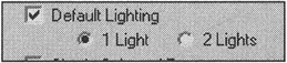
For further work, it makes sense to activate the default sources of light:
-
Viewport context menu à Configure à Rendering Method à Rendering Options à Default Lighting
-
The only object of our scene that requires assignment and adjustment of the Explicit texture coordinate is Inner Walls. The armchairs and the sofa will be assigned a one-color material, and a procedure texture will be used for the pattern. The sashes and the door also will be "painted" one color. The curtains were assigned texture coordinates at their creation.
-
Select the Inner Walls object using selection by name (<H> key) and hide all the other objects. Thus, it will be more convenient to assign materials and texture to the object:
-
Context menu à Hide Unselected
-
If you did the first project, then it will not be difficult for you to create materials, assign them correctly to objects, and adjust texture coordinates. We, however, would like to consider in more detail all possible methods of assigning materials and imposing texture coordinates on an object as simple as our room. You may learn something new that will be to your liking.
The first method is based on application of a Multi/Sub-object material, which was created automatically when materials were assigned to the various parts of the object. Then, the Poly Select and UVW Map modifiers are used to adjust the texture coordinates for each of the selected polygons. This is our favorite method, although it's not without drawbacks. The main drawback is the need for complete attention and accuracy when working with the stack, because any casual action may lead to nearly irreparable consequences.
The second method is also based on the application of a Multi/Sub-object material, but adjustment of the texture coordinates is carried out slightly differently. Starting from the third version of 3ds max, there is an option to assign up to 99 texture channels (Map Channels) to the texture using Explicit Map Channel. The ratio is easily defined: The Map Channel parameter in the material editor should correspond to the one in UVW Map modifiers. Then adjustment comes to successive application of UVW Map modifiers to the whole object, each of the modifiers determining the texture coordinates for the corresponding channel. Although this may seem complex, the process allows you to efficiently employ one simple material with a Composite texture. We usually try to avoid such exotics unless they are justified, but this one at times is the only solution (for example, if a logo is imposed on a surface that already has an assigned texture).
| Note | Some people may wish to make computer graphics as "showy" as possible. They often are either beginners who take every revelation as a call for action, or skilled professionals who are simply "playing to the max." However, those who treat computer graphics as a means of livelihood, not as an end in itself, are apt to find the simplest and most efficient methods for gaining their final result. |
The third method that we recommend is to split the object into independent objects, assign a simple material to each object, and texture each one separately.
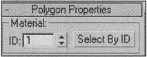
Before you split the object, you can assign the same Material ID to all polygons. This will help you avoid problems later on when you merge the objects back into one.
-
Select all polygons and assign the same material index to all of them:
-
Control panel à Polygon Properties à "1" for Material
-
-
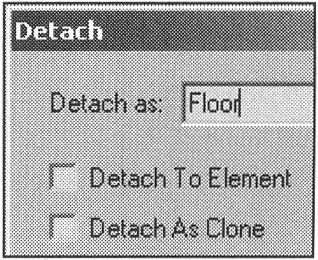
Successively select the polygons corresponding to these elements and Detach them to create new objects:
-
Control panel à Edit Geometry à Detach
-
| Tip | Some polygons are convenient to select on straight projections (e.g., on the Left view). Uncheck the Ignore Backfacing flag. |
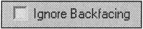
Fig. 11.1 shows all of the resultant objects. To make the figure more demonstrative, we separated the objects. (You do not need to do this.) Note that we created a separate object (Diagonal Wall) for one of the walls. Later we will explain its purpose.
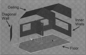
Figure 11.1: Splitting the Inner Walls object
You have to create and assign three materials: for the floor, the walls, and the ceiling. Those for the floor and the walls will contain textures loaded from files with raster images. The corresponding objects want explicit indication of the texture coordinates. The ceiling material can be easily implemented using procedure textures; you don't have to assign texture coordinates on the ceiling.
| Note | If you've seen the final reel, you might have been horrified. We agree that a ginger polished table, tastelessly patterned blue wallpaper with no less tasteless violet curtains, and cream-colored furniture are a bit excessive. All this "grandeur" was made deliberately to demonstrate possible problems and ways of coping with them. Hopefully, you have good taste and will be able to match the textures and materials so that you would want to live in this room. If colors are matched perfectly, it is possible that no additional settings will be needed. |
Generally, a Blinn type of Shader may be used on all three materials. Make all materials lusterless by specifying the bas parameters shown in Fig. 11.2.
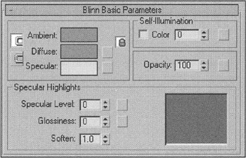
Figure 11.2: Basic parameters of the materials for the floor, walls, and ceiling
| Tip | Adjust one material, then duplicate it by transferring it to the neighboring preview window (Material Slot) of the material editor. Rename each material Floor, Walls, and Ceiling, respectively. |
When creating materials for use with the global lighting system, remember that direct light (in our case, from the Sun (IES Sun)) affects the Specular and Diffuse channels, whereas reflected light and that of the "sky" (IES Sky or SkyLight) affect the Ambient channel. For correct rendering, the colors and the textures imposed on the Diffuse and Ambient channels must match. That is the default state of materials in 3ds max, indicated by the pressed buttons locking (Lock) the Ambient and Diffuse colors and textures. If you wish, you can get interesting effects by toggling off these links and "playing" with the colors and textures.
-
Assign appropriate textures on the Diffuse channel of the Floor and Walls materials. We used the texture files supplied with 3ds max. You can also use any file from your own library of textures:
-
Material editor à button in Diffuse line
-
Material/Map Browser à Bitmap
-
To assign textures from raster image files, you can use the Asset Browser module. Select the required file and transfer it with a button.
| Note | Quite unexpectedly, we got to know another feature of 3ds max. You can transfer raster images directly on objects and selected sub-objects. The procedure creates the material, with the corresponding jmage merged on its Diffuse channel. In the case of sub-objects, a Multi/Sub-object material is created. Many are the mysteries of 3ds max, indeed! |
-
Assign materials to the objects: the Floor material to the Floor object, the Walls material to the Inner Walls and Diagonal Wall objects, the Ceiling material to the Ceiling object. It is convenient to select the objects by name and assign the materials using the Assign Material to Selection button.
-
In the materials' parameters, toggle on the materials' display in the viewport. The objects will be painted the colors of the textures, but no textures will be visible.
-
Assign texture coordinates to the objects using the UVW Map modifier:
-
Main menu à Modifiers à UV Coordinates à UVW Map
-
Planar coordinates will do for the floor (Fig. 11.3, a). There are a few ways of setting the coordinates, but in our case it is convenient to change the size and position of the modifier's Gizmo. Distorting the texture looks bad, so you can bring the size of the modifier's gizmo into accordance with that of the texture file by pressing the Bitmap Fit button and selecting the texture file. Then scale by two coordinates, retaining the sides ratio, to change the dimensions.
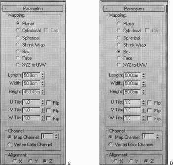
Figure 11.3: Editing texture coordinates
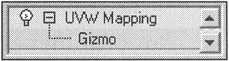
For walls oriented to each other at right angles, the Box type will do (Fig. 11.3, b). If the walls are not at right angles, this type is bound to introduce inevitable distortions. Therefore, the separate Diagonal Wall object was created. To texture it, copy and transfer the modifier from the Inner Walls, then orient the modifier's gizmo using the Normal Align command.
Make the material of ceiling bright. Don't assign textures for existing channels. After all coordinates are adjusted, merge all of the objects into one.
-
Select the Inner Walls object and Attach the rest of the objects to it using selection-by-name:
-
Context menu à Attach à select all objects in the list
-
-
In the Attach Options window, choose Match Material IDs to Material in response to the question about the materials assigned to the objects (Fig. 11.4).
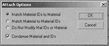
Figure 11.4: Attach Options window -
Select any free preview window in the material editor and load the material into it using the "dropper" (Pick Material from Object). As you can see, the material consists of three sub-materials (Fig. 11.5). Rename the material Room.
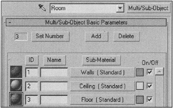
Figure 11.5: Structure of the Room material -
Unhide the Outer Walls and Window Frame## objects:
-
Context menu à Unhide by Name
-
-
Create a bright material, rename it Frames, and assign it to the sashes (Window Frame## objects).
-
Assign any Default material to the Outer Walls object.
Now you can render the global lighting. We assume that the objects' parameters responsible for global lighting are specified as described in Lesson 10.
-
Open the advanced lighting window and activate radiosity:
-
Main menu à Rendering à Advanced Lighting à Radiosity
-
-
Specify the Initial Quality parameter equal to 50%. (This will do for quick rendering.) Start rendering.
The resulting scene will be overexposed (Fig. 11.6, a). The Exposure Control process can help you adjust the brightness (Fig. 11.6, b).
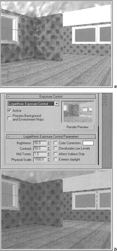
Figure 11.6: Result of radiosity quick rendering without (a) and with (b) the exposure control process
There is yet another problem: painting the walls and the ceiling with the floor-texture color. In reality, if you enter an empty room on a bright, sunny day, you will see a similar effect: The painting is too strong and needs to be reduced.
| Note | Further editing depends on the textures you applied to the objects. We already pointed out the purpose of our coloring. You will have to correct the settings yourself. You can find our file (lesson11-02.max) in the \Lessons\Lesson11\Scenes folder on the CD-ROM. |
In the material editor of 3ds max 5, there is the option to redistribute the reflected and transmitted light. To use this option, activate the display of this information (Fig. 11.7, a):
-
Main menu à Customize à Preferences à Advanced Lighting à Display Reflectance and Transmittance Information
![]()
Figure 11.7: Activating the display of materials' light distribution (a) and a corresponding line in the material editor (b)
For each material in the material editor, a line will display the average and the maximal Reflectance and Transmittance values (Fig. 11.7, b).
| Note | You can use this option only if your 3ds max has been updated to version 5.1 or later. It option does not work in the previous release (5.0). |
The developers of 3ds max recommend adjusting materials so that the reflected energy for non-brilliant materials remains 20–50%.
To adjust the materials using the global lighting system, there is a special type of material provided in 3ds max: the composite Advanced Lighting Override material. It enables you to adjust the light without changing the original material.
-
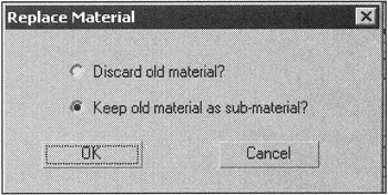
Use Advanced Lighting Override, for the Room material leaving the original material as a sub-material. Rename the material Room Override.
-
Material editor à Room + Advanced Lighting Override
-
Select "Keep old material as sub-material?" in the Replace Material window
-
We obtained a decent result with the parameters in Fig. 11.8. Now, let us consider in detail the meanings of these parameters.
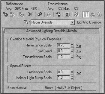
Figure 11.8: Advanced Lighting Override parameters
-
Reflectance Scale enables you to change the degree of reflection according to the material's surface. We slightly reduced this parameter and obtained the cherished 40% for the average value of the reflected energy.
-
Color Bleed enables you to change the degree of the object's illumination by reflected light. We considerably reduced this parameter.
-
Transmittance Scale enables you to change the degree of light transmission by the object. This is used for semi-transparent objects.
-
Luminance Scale emits light from objects assigned a self-luminous material.
-
Indirect Light Bump Scale enables you to solve problems that may occur with indirect light (e.g., "saturating" a bump).
During material adjustment, you will have to render radiosity several times. When materials' parameters are changed, new rendering is required. To do this, press the Reset button before rendering is started. If objects in the scene were moved, it is necessary to press the Reset All button.
After the material for the room is adjusted, all objects should be unhidden. Then creat and adjust the materials for them.
You can find our variant in the ![]() Lesson11(Final).max file on the CD-ROM in the Lessons\Lesson11\Scenes folder. Below is a brief description of what was done.
Lesson11(Final).max file on the CD-ROM in the Lessons\Lesson11\Scenes folder. Below is a brief description of what was done.
First we worked with the room materials. A texture was added to the floor material, and it was made slightly glossy by transferring the texture from the Diffuse channel to the Bump, Glossiness, and Specular Level channels. Low Amount values were set for these channels (Fig. 11.9, a).
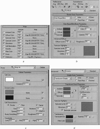
Figure 11.9, a—d: Final material and effects settings
Then we added the Raytrace texture to the Reflection channel with a small Amount value. Apart from the reflection itself, this gives us the option of using an interesting effect, which will be described later.
The Oren-Nayar-Blinn shader was used for the furniture. The colors on the Ambient and Diffuse channels were made very dark; otherwise, at final rendering, these objects would be too bright (Fig. 11.9, b). We applied a Cellular procedural texture to the bump channel (Fig. 11.9, c).
The Translucency shader was used for the curtains. This shader gives us an option to reduce overexposure. We made the color almost black on this channel; otherwise the exposure would have been too bright. This material is 2-Sided (Fig. 11.9, d).
We also glazed the windows. The windowpanes are typical Plane objects. We used an almost transparent Raytrace material with Fresnel reflection (Fig. 11.9, e).
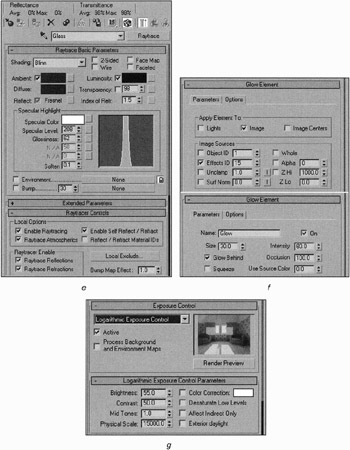
Figure 11.9, e—g: Final material and effects settings
To obtain a slight glow around the windows and its reflection on the floor, we added the Glow effect. It was adjusted so that only the window-panes glow. To do this, we set the Material Effect Channel of the windowpane material to 15. Then we matched the same parameter of the effect. The intensity of the glow was slightly reduced (Fig. 11.9, f).
Since the material effect channel is used for this effect, a slight glow appears around the reflection of the window on the floor. To enable this effect, check the Reflect/Refract Material ID flag in the parameters of the Raytrace texture of the Floor material. Note that the same flag in the windowpane parameters should be deactivated; otherwise, the glow will be created only on the floor.
Finally, to make the windows are bright after rendering, we increased the Physical Scale value in the exposure control parameters (Fig. 11.9, g).
After all materials are adjusted, you can render the global lighting with high quality (Fig. 11.10).
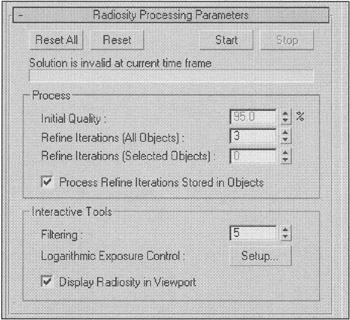
Figure 11.10: Final radiosity parameters
| Note | Lately it has become all the rage to create interactive panoramas in QTVR (Quick Time Virtual Reality) format. Unfortunately, the developers of 3ds max did not deem it necessary to create such panoramas in the base supply of the package. However, Autodesk VIZ 4, the "younger brother" of 3ds max, has such a module. You can use it by loading the 3ds max supplement named Design Extensions from the http://www.discreet.com/ website. But, to be frank, this is not the best solution. In this module, the so-called "cubic panorama" is used to create panoramas with six cameras with a 90° visual angle. Our practice proves that a panorama based on photographs works better. During the process, the file sequence is obtained by rendering from the animated camera view. Of course, the best solution is to use the RealViz Stitcher package, but it is rather expensive: about $500. You can find a panorama package at a reasonable price at http://www.panoguide.com/. |
We propose that you make a panoramic reel for 7 seconds, with the camera rotating around its axis.
To animate the rotation of the camera:
-
Specify the animation parameters Fig. 11.11. Set the picture frequency to 15 frames per second and the duration to 7 seconds:
-
Time control panel à Time Configuration
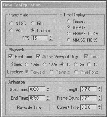
Figure 11.11: Animation parameters -
-
Move the camera to the center of your room and change its type to Target Camera.
-
Make Circle on the Top view Fig. 11.12. This will be the path for the target of the camera.
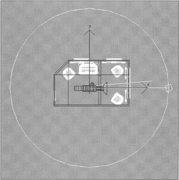
Figure 11.12: Animation of the camera -
Raise it on the Left view to the camera level.
-
Select the Camera01.Target object and assign the Path Constraint animation controller:
-
Main menu à Animation à Constraints à Path Constraint
-
Draw a "line" to the circle and click with the left mouse button.
-
Play the animation in the viewport. The camera turns around its axis following the target moving on the circle.
Now, everything is ready for final rendering!
-
Go to the camera view and set the rendering parameters (Fig. 11.13):
-
Main menu à Rendering à Render
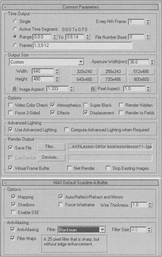
Figure 11.13: Rendering parametersExplanation The rendering parameters are considered in detail in Lesson 8. Here we will only clarify the most pertinent points.
Set the Range one frame less than the duration of the animation. This will help you avoid a "break" when playing looped animation.
Set the frame size as 640 × 480 pixels.
Check the Use Advanced Lighting flag.
Activate the Save File option. You can save your animation directly as a video file (AVI or MOV). We prefer rendering to TGA files with further compilation of the reel in a video editor.
Use Anti-Aliasing at your own discretion. We decided that in this case, the Blackman type provided the best picture quality.
-
-
Do the final rendering.
In the end, we recommend that you use the IES Sun and IES Sky sources of light only when you want a physically correct distribution of light. If a nice picture is your goal, it makes sense to use a Direct light source as the Sun, and Skylight as the sky. This gives you more control over the lighting.
|
| < Day Day Up > |
|
EAN: N/A
Pages: 136