Spaceship Flight Animation
|
| < Day Day Up > |
|
To learn more about animation, we will proceed by more complicated means than necessary. In this lesson, we will consider the Path Constraint in detail and teach you its wonderful features in 3ds max.
| Note | If you want to accomplish the same task in an easier way — do it. |
Before we proceed, it is a good idea to set the time scale. It is our rule to do it right away, although 3ds max allows you to reset these parameters at any time.
-
Open the time scale parameters window and set them as shown in Fig. 5.3:
-
Time control panel à Time Configuration
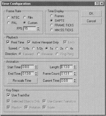
Figure 5.3: Time Configuration window
-
| Explanation | Use 15 frames per second for the Frame Rate. We plan to show the clip on a computer screen, so that should do. The Time Display group determines the format in which time will be displayed on the scale. It is convenient to use the SMPTE format, where time is displayed as "minutes:seconds:frames." The Playback group determines the rate and direction of animation in the viewport. Do not change these parameters. Use the Animation group to set the length of animation. We will need approximately 5 seconds for the space panorama and 7 seconds for the flight. If this is not enough, you can change these parameters at any time. 3ds max has a cunning way to change the duration without opening this window. Move the cursor to the time scale and press the <Ctrl> and <Alt> keys. The start or end time is changed according to which mouse button is pressed. Move the mouse along the horizontal axis: the left button will affect the first frame of the active segment, the right button — the final frame. Pressing the middle button will change the active segment. It may be intriguing, but this option is not particularly convenient; we discovered it by accident. |
Now, you can load the spaceship and lunar module, but we discourage you from doing so. It is easier and quicker to configure the animation for a simple object and load the real objects at the end.
-
Create an object of any type at any place — we used a Box.
-
Rename it SpaceShip-Base.
-
On the Top view, make two simple Line objects as shown in Fig. 5.4, a. They should have the same length and lie in the same direction — from the left to the right, in our case.
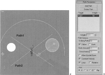
Figure 5.4, a and b: Object animation by path -
Rename them Path1 and Path2, respectively.
-
Select the SpaceShip-Base and assign the Path Constraint controller to it.
-
Main menu à Animation à Constraints à Path Constraint
-
Drag to Path1 and click the left mouse button.
-
The SpaceShip-Base will move to the start of the path. Start playback of the animation. It will move along the straight line!

When a Constraints controller is assigned, the control panel automatically toggles to the Motion view with the parameters of the controller. Set them according to Fig. 5.4, b.
| Explanation | In the third lesson, we considered the similar LookAt Constraint in detail, so we will only discuss the features specific to Path Constraint here. The Add Path and Delete Path buttons indicate that objects can move simultaneously along several paths. The Weight parameter controls the path the object will take at any specific moment. There is only one path in the list so far, and the Weight window is inactive. The %Along Path parameter controls the object's position along the path. You can see that the spinner of this parameter is highlighted by red corners. This denotes that it is animated. Look at the time scale and notice two red rectangles — keys. By moving their position on the scale, you change when the motion starts and ends. The Follow flag is used to turn an object corresponding to the direction of motion. The Bank flag is used to tilt like an airplane. The object's orientation during motion is determined by the the Axis group. The Allow Upside Down flag allows the object to do just that. The Constant Velocity flag makes the object move at a constant speed along the entire path. Otherwise, the distance between vertices dictates the speed: the shorter the distance, the slower the movement. It is not important in our case, because there are only two vertices. The Loop flag allows an object to loop around a path only if the path is closed. The Relative flag enables the object to retain its original position. |

Add the second path by pressing the Add Path button and clicking with the left mouse button on the Path2 object. Things are a bit different now. The object will move at the same distance from both paths.
Let's make the object go from one path to the other:
-
Go to the first frame of animation by pressing the <Home> key.
-
Leave the weight of the first path equal to 50 and enter 0 for the second path (Fig. 5.4, c). Notice that the object moves to the start of the first path.
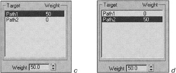
Figure 5.4, c and d: Object animation by path -
Go to the last frame (<End> key), activate the recording of the animation by pressing the Auto Key button, and invert the path weights (Fig. 5.4, d).

| Note | Don't forget to deactivate the Auto Key button after the keys are set! |
Play the animation, or simply move the slider. As you can see, the object smoothly goes from one path to the other.
You can change the object's trajectory by moving the paths and their vertices. By opening the curve editor and adjusting the Weight0 and Weight1 curves, you can get a steeper turn (Fig. 5.5). It is important that the object flies in front of the camera (i.e., the camera does not have to turn around its axis to see the action).
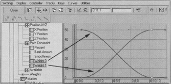
Figure 5.5: Curve editor

The result of our work is on the CD-ROM in ![]() lesson05-02.max.
lesson05-02.max.
|
| < Day Day Up > |
|
EAN: N/A
Pages: 136