Lunar Rover Modeling
|
| < Day Day Up > |
|
After modeling the spaceship and lunar module, modeling the lunar rover should not present any difficulties (Fig. 3.23). It looks less like a Russian "Lunokhod" than an American "Rover" in terms of size and functionality, and we will therefore use that designation.
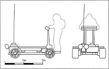
Figure 3.23: Lunar rover sketch
The rover-not-assembled.max file on the CD-ROM in the Lessons\Lesson 03\ scenes folder contains our model. All objects are independent, and the modifier stacks are left as they are. After studying this file, you will have an exhaustive idea of the modeling process. We made about 70 objects, most of them primitives and rotation objects (Lathe) constructed by curves.
The rover-assembled.max file contains the same model, but with 9 objects — only those necessary for animation. These are: base frame (ROVER Base), body (ROVER bodywork), four wheels (ROVER xx Wheel), two auxiliary objects to turn the rear wheels (ROVER xx Turner), and antenna (ROVER Antenna).
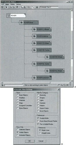
The rover-linked.max file contains the model linking the objects as shown in Fig. 3.24. As you can see, we used a Dummy object, which we named ROVER. As you may guess, this object serves the same role as the LUNAR SHIP: It is the "ancestor" for all the other objects. The pivot points were set in the same way as those of the landing props. In addition, some objects were mirrored (Mirror) when copying: the right wheels and the Rover RR Turner object. To avoid difficulties during animation, the Reset XForm operation was applied to them:
-
Control panel à Utilites à Reset XForm
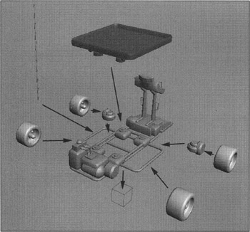
Figure 3.24: Merging the lunar rover objects
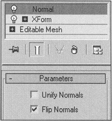
If, as a result of this procedure, an object's normal becomes inverted, you can correct it with the Normal modifier using the Flip Normals flag:
-
Main menu à Modifiers à Mesh Editing à Normal Modifier
When you are done, Collapse the stack of modifiers for all objects:
-
Context menu à Collapse All
| Explanation | Using the Mirror command in 3ds max is one of many puzzles. The idea is that it does nothing but scale the object by -100% and, as a rule, is only done with respect to one axis (i.e., Non-Uniform Scale). 3ds max programmers discourage such scaling, preferring the XForm modifier and scaling the container of the modifiers. |
| Tip | The Schematic View is useful to link a lot of objects by representing the scene as a tree (Fig. 3.25, a). You can open it as a separate window (Main menu à Graph Editors à New Schematic View) or in one of the viewports (Viewport context menu à Views à Schematic). We do not think it is very useful in general (it is possible to do everything without it), but it is convenient to link objects by pressing the Filters button to set the parameters as shown in Fig. 3.25, b. |
The rover's materials are also straightforward. There are a few raster textures for the treads and monitors, and the rest are procedural. We simply made one Multi/Sub-object material (based on the sub-objects), assigned it to all the objects, and changed the Material ID for the polygons. The structure of this material is shown in Fig. 3.26. Frankly speaking, it is a bit untinished, and we will need to edit this material further and discuss to what extent it is prudent later.
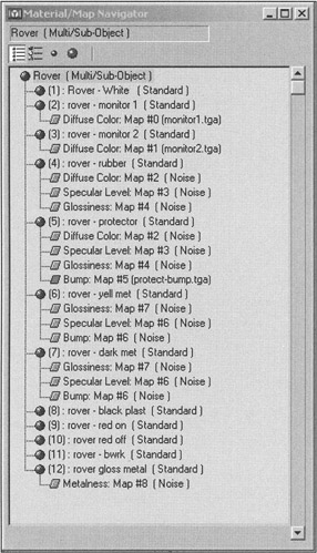
Figure 3.26: Material structure of the lunar rover
You can find our version of the lunar rover in ![]() Lesson03(rover-final).max (Fig. 3.27).
Lesson03(rover-final).max (Fig. 3.27).
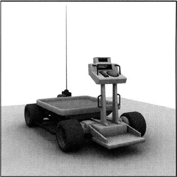
Figure 3.27: Final appearance of the lunar rover
Finally, we want to make a statement with which we think you will agree. It turned out that working with meters as the unit of measurement was not very convenient. As a rule of thumb, the system units should be a couple of orders of magnitude less than the average dimensions of the object — we should have operated with centimeters or inches. It is a good idea to keep this in mind in the future.
|
| < Day Day Up > |
|
EAN: N/A
Pages: 136