Network Installation Tools
|
|
When installing network components, oftentimes you will have to use some very specialized tools. These tools are used mainly in the telecommunications industry. In this section, you will learn about the most common network installation tools, including:
-
Wire crimper
-
Media tester (including copper and fiber-optic)
-
Punchdown tool
Wire Crimper
A wire crimper (or “crimper” as it is more commonly known) is a hand tool found in most network technicians’ tool bags. Crimpers are primarily used for attaching ends onto different types of network cables by a process known as crimping. Crimping involves using pressure to press some kind of metal teeth into the inner conductors of a cable. An example of a crimper is shown in Figure 6.20.
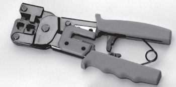
Figure 6.20: An example of a crimper
| Note | Contrast this with punching down, which involves pushing the conductor into the metal teeth. |
Many network technicians will make patch cables with a crimper. They will take a small piece of Category 5 UTP and crimp two RJ-45 ends on it to make the cable. Additionally, there are crimpers for the other types of cable, as well. There are even crimpers available for crimping on fiber-optic ends.
Media Testing Tools
The best method for addressing a faulty cable installation is to avoid the problem in the first place by purchasing high-quality components and installing them carefully. But no matter how careful you are, problems are bound to arise. This section covers the tools that you can use to test cables both at the time of their installation and afterward, when you’re troubleshooting cable problems. Cable testing tools can range from simple, inexpensive mechanical devices to elaborate electronic testers that automatically supply you with a litany of test results in an easy-to-read pass/fail format.
The following sections list the types of tools that are available for both copper and fiber-optic cable testing. This is not to say that you need all of the tools listed here. In fact, some of the following sections attempt to steer you away from certain types of tools. In some cases, there are both high-tech and low-tech devices available that perform roughly the same function, and you can choose which you prefer according to the requirements of your network, your operational budget, or your temperament. Some of the tools are extremely complicated and require extensive training to use effectively, while others are usable by anyone who can read.
You should select the types of tools you need based on the descriptions of cable tests given earlier in this chapter, the test results required by the standards that you’re using to certify your network, and the capabilities of the people who will be doing the actual work—not to mention the amount of money you want to spend.
Wire Map Testers
A wire map tester is a device that transmits signals through each wire in a copper twisted-pair cable to determine if it is connected to the correct pin at the other end. Wire mapping is the most basic test for twisted-pair cables because the eight separate wire connections involved in each cable run are a common source of installation errors. Wire map testers detect transposed wires, opens (broken or unconnected wires), and shorts (wires or pins improperly connected to each other)—all problems that can render a cable run inoperable.
Wire map testing is nearly always included in multifunction cable testers, but in some cases it may not be worth the expense to spend thousands of dollars on a comprehensive device. Dedicated wire map testers are relatively inexpensive (from $200 to $300) and enable you to test your installation for the most common faults that occur during installations and afterward. If you are installing voice-grade cable, for example, a simple wire mapping test may be all that’s needed. There are also slightly more expensive (under $500) devices that do wire map testing in addition to other basic functions, such as TDR length testing.
A wire map tester consists of a remote unit that you attach to the far end of a connection and the battery-operated, hand-held main unit that displays the results. Typically, the tester displays various codes to describe the type of faults that it finds. In some cases, you can purchase a tester with multiple remote units that are numbered, so that one person can test several connections without constantly traveling back and forth from one end of the connections to the other to move the remote unit.
| Warning | The one wiring fault that is not detectable by a dedicated wire map tester is split pairs, because even though the pinouts are incorrect, the cable is still wired straight through. To detect split pairs, you must use a device that tests the cable for the near-end crosstalk that split pairs cause. |
Continuity Testers
A continuity tester is an even simpler and less expensive device than a wire map tester. It is designed to check a copper cable connection for basic installation problems, such as opens, shorts, and crossed pairs. At $50 to $200, these devices usually cannot detect more complicated twisted-pair wiring faults such as split pairs, but they are sufficient for basic cable testing, especially for coaxial cables, which have only two conductors that are not easily confused by the installer. Like a wire map tester, a continuity tester consists of two separate units that you connect to each end of the cable to be tested. In many cases, the two units can snap together for storage and easy testing of patch cables.
Tone Generators
The simplest type of copper cable tester is also a two-piece unit and is called a tone generator and probe, also called a “fox and hound” wire tracer. This type of device consists of one unit that you connect to a cable with a standard jack, or to an individual wire with alligator clips, which transmits a signal over the cable or wire. The other unit is a penlike probe that emits an audible tone when touched to the other end of the cable or wire or even to its insulating sheath.
This type of device is most often used to locate a specific connection in a punchdown block. For example, some installers prefer to run all of the cables for a network to the central punchdown block without labeling them and then to use a tone generator to identify which block is connected to which wall plate and label the punchdown block accordingly. You can also use the device to identify a particular cable at any point between the two ends. Because the probe can detect the cable containing the tone signal through its sheath, it can help you to locate one specific cable out of a bundle in a ceiling conduit or other type of raceway. You just need to connect the tone generator to one end and touch the probe to each cable in the bundle until you hear the tone.
In addition, by testing the continuity of individual wires using alligator clips, you can use a tone generator and probe to locate opens, shorts, and miswires. An open wire will not produce a tone at the other end, a short will produce a tone on two or more wires at the other end, and an improperly connected wire will produce a tone on the wrong pin at the other end.
This process is extremely time-consuming, however, and it’s nearly as prone to errors as the cable installation itself. You either have to continually travel from one end of the cable to the other to move the tone generator unit, or use a partner to test each connection, keeping in close contact using radios or some other means of communication in order to avoid confusion. When you consider the time and effort involved, you will probably find that investing in a wire map tester is a more practical solution.
Optical Loss Test Set
In most cases, you’ll need both an optical power meter and a test source in order to properly install and troubleshoot a fiber-optic network, and you can usually save a good deal of money and effort by purchasing the two together. This practice ensures that you’re purchasing units that both support the wavelengths and power levels you need and are calibrated for use together. You can purchase the devices together in two ways: as a single combination unit called an optical loss test set (OLTS) or as separate units in a fiber-optic test kit.
An OLTS is generally not recommended for field testing, because it is a single unit. While useful in a lab or for testing patch cables, two separate devices would be needed to test a permanently installed link, because you have to connect the light source to one end of the cable and the power meter to the other. However, for fiber-optic contractors involved in large installations, it may be practical to give workers their own OLTS so that they can work with a partner and easily test each cable run in both directions.
Fiber-optic test kits are the preferable alternative for most fiber-optic technicians because they include a power meter and light source that are designed to work together, usually at a price that is lower than the cost of two separate products. Many test kits also include an assortment of accessories needed to test a particular type of network, such as adapters for various types of connectors, reference test cables, and a carrying case. Prices for test kits can range from $500 to $600 for basic functionality to as much as $5,000 for a comprehensive kit that can test virtually every type of fiberoptic cable.
| Tip | Communications can be a vital element of any cable installation in which two or more people are working together, especially when the two ends of the permanent cable runs are a long distance apart, as on a fiber-optic network. Some test sets address this problem by incorporating voice communication devices into the power meter and light source, using the tested cable to carry the signals. |
Multifunction Cable Testers
The most heavily marketed cable testing tools available today are the multifunction cable scanners, sometimes called certification tools. These are devices that are available for both copper and fiber-optic networks. They perform a series of tests on a cable run, compare the results against either preprogrammed standards or parameters that you supply, and display the outcome as a series of pass or fail ratings. Most of these units perform the basic tests called for by the most commonly used standards—such as wire mapping, length, attenuation, and NEXT for copper cables—and optical power and signal loss for fiber-optic. Many of the copper cable scanners also go beyond the basics to perform a comprehensive battery of tests, including propagation delay, delay skew, PS-NEXT, ELFNEXT, PS-ELFNEXT, and return loss.
The primary advantage of this type of device is that anyone can use it. You simply connect the unit to a cable, press a button, and read off the results after a few seconds. Many units can store the results of many individual tests in memory, download them to a PC, or output them directly to a printer.
This primary advantage, however, is also the primary disadvantage of this type of device. The implication behind these products is that you don’t really have to understand the tests being performed, the results of those tests, or the cabling standards used to evaluate them. The interface insulates you from the raw data, and you are supposed to trust the manufacturer implicitly and believe that a series of pass ratings means that your cables are installed correctly and functioning properly.
The fundamental problem with this process, however, is that the standards used to assess the test results gathered by the device are not necessarily reliable. Some units claim to certify Category 6 and Category 7 cables, for example, when standards for these cables have not yet been ratified. One must even question the validity of the testers that claim to certify Category 5e cables, since this standard was ratified only recently. When evaluating products like these, it’s important to choose units that are upgradable or manually configurable so that you can keep up with the constantly evolving standards.
This configurability can lead to another problem, however. In many cases, it isn’t difficult to modify the testing parameters of these units to make it easier for a cable to pass muster. For example, simply changing the NVP for a copper cable can make a faulty cable pass the unit’s tests. An unscrupulous contractor can conceivably perform a shoddy installation using inferior cable and use his own carefully prepared tester to show the client a list of perfect “pass” test results.
As another example, some of the more elaborate (and more expensive) fiber-optic cable testers attempt to simplify the testing process by supplying main and remote units that contain both an integrated light source and semiconductor detector and then by testing at the 850nm and 1,300nm wavelengths simultaneously. This type of device enables you to test the cable in both directions and at both wavelengths simply by connecting the two units to either end of a cable run. There is no need to use reference test cables to swap the units to test the run from each direction or run a separate test for each wavelength.
However, these devices, apart from costing several times as much as a standard power meter and light source combination ($4,000 or more, in some cases), do not compare the test results to a baseline established with that equipment. Instead, they compare them to preprogrammed standards, which, when it comes to fiber-optic cables, can be defined as somewhat loose. The result is a device that is designed for use primarily by people who really don’t understand what they are testing and who will trust the device’s pass or fail judgment without question, even when the standards used to gauge the test results are loose enough to permit faulty installations to receive a pass rating.
This is not to say that these multifunction devices are completely useless. In fact, they can be an extremely efficient means of testing and troubleshooting your network. The important thing to understand is what they are testing and to either examine the raw data gathered by the unit or verify that the standards used to formulate the pass/fail results are valid. The prices of these products can be shocking, however. The cost of both copper and fiber-optic units can easily run up to several thousand dollars, with top-of-the-line models exceeding $5,000.
Punchdown Tool
Most networks today are built using twisted-pair cable of some sort. This cable is usually terminated in wiring closets using a tool known as a punchdown tool. It is called that because, essentially, the tool punches down the wire into some kind of insulation displacement connector (IDC). IDCs make contact by cutting through, or displacing, the insulation around a single conductor inside a twisted-pair cable. The punchdown tool pushes a conductor between the sides of a “V” inside an IDC (see Figure 6.21), allowing the small metal “knife” inside the connector to make contact with the inner conductor inside the wire.
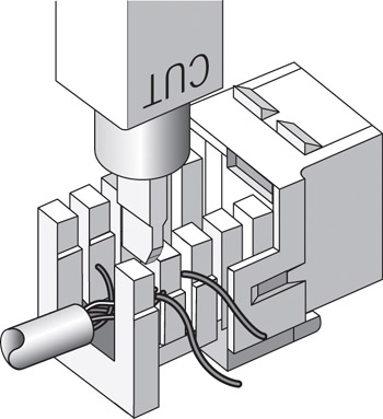
Figure 6.21: Using a punchdown tool
There are different blades and different types of punchdown tools. The most common is the punchdown with replaceable blades for the different types of connectors (either 66 or 110). Figure 6.22 shows an example of one of these types of punchdown tools.
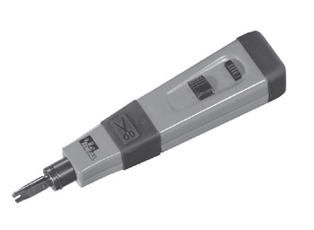
Figure 6.22: An example of a punchdown tool
|
|
- Challenging the Unpredictable: Changeable Order Management Systems
- ERP System Acquisition: A Process Model and Results From an Austrian Survey
- The Second Wave ERP Market: An Australian Viewpoint
- Enterprise Application Integration: New Solutions for a Solved Problem or a Challenging Research Field?
- A Hybrid Clustering Technique to Improve Patient Data Quality