The OSI Model s Middle Layers
|
|
The OSI Model’s Middle Layers
As you move up the OSI model, the protocols at each successive layer get more complex and have more responsibilities. At the middle are the Network and Transport layers, which perform the bulk of the work for a protocol stack. You’ll see why in the sections to follow.
The Network Layer
The Network layer of the OSI model defines protocols that ensure that the data arrive at the correct destination. This is probably the most commonly discussed layer of the OSI model.
Network Layer Concepts
The most important Network layer concepts are:
-
Logical network addressing
-
Routing
Logical Network Addressing
In the last section, you learned that every network device has an address (the MAC address) assigned at the factory and that this address is protocolindependent. But, as you know, most networks communicate using protocols that must have their own addressing scheme. If the MAC address is the Data Link layer physical address, the protocol-addressing scheme at the Network layer defines the logical address.
| Note | If IP addresses are duplicated on Windows 95/98 workstations, the first station that is assigned an address gets to use it. Any other station that has that address receives error messages about duplicated IP addresses. The address is then unassigned. The first station receives error messages as well, but it can continue to function. |
Each logical network address is protocol-dependent. For example, a TCP/ IP address is not the same as an IPX address. Additionally, the two protocols can coexist on the same computer without conflict. However, two different stations using the same protocol cannot have the same logical network address on the same network. If that happens, neither station can be seen on the network (see Figure 2.16).
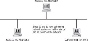
Figure 2.16: Address conflicts on a network
| Note | Address conflicts can be common with TCP/IP because an administrator often needs to assign IP addresses. IPX addresses don’t suffer from conflict nearly as often, because they use the MAC address as part of the IPX address. The MAC address is unique and can’t be changed. For more information on network addresses, see Chapter 4, “TCP/IP Utilities.” |
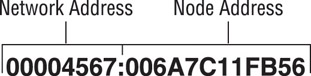
Whenever you have to set up a network or add a station, it is important to have an understanding of how network addresses work. Every network address in either TCP/IP or IPX has both a network portion and a node portion. The network portion is the number that is assigned to the network segment to which the station is connected. The node portion is the unique number that identifies that station on the segment. Together, the network portion and the node portion of an address ensure that a network address will be unique across the entire network.
IPX addresses use an eight-digit hexadecimal number for the network portion. This number, called the IPX network address, can be assigned randomly by the installation program or manually by the network administrator. The node portion is the 12-digit hexadecimal MAC address assigned by the manufacturer. A colon separates the two portions. Here is a sample IPX address:
TCP/IP addresses, on the other hand, use a dotted decimal notation in the format xxx.xxx.xxx.xxx as shown in the following:
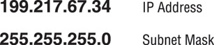
The address consists of four collections of eight-digit binary numbers (or up to three decimal digits) called octets, separated by periods. Each decimal number in an IP address is typically a number in the range of 1 through 254. Which portion is the network and which portion is the node depends on the class of the address and the subnet mask assigned with the address. A subnet mask is also a dotted decimal number with numbers in the range of 0 through 255. If a subnet mask contains 255 in any position ( corresponding to a binary number of all ones), the corresponding part of the IP address is the network address. For example, if you have the mask 255.255.255.0, the first three octets are the network portion, and the last portion is the node.
Routing
Routing is the process of moving data throughout a network, passing through several network segments using devices called routers, which select the path the data takes. Placing routers on a network to connect several smaller routers turns a network into an entity known as an internetwork. Routers get information about which paths to take from files on the routers called routing tables. These tables contain information about which router network interface (or port) to place information on in order to send it to a particular network segment. Routers will not pass unknown or broadcast packets. A router will route a packet only if it has a specific destination. Figure 2.17 illustrates these components and their participation in the routing process.
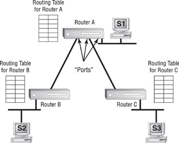
Figure 2.17: Routing components
Information gets into routing tables in two ways:
-
Through static routing
-
Through dynamic routing
In static routing, the network administrator manually updates the router’s routing table. The administrator enters every network into the routing table and selects the port on which the router should place data when the router intercepts data destined for that network. Unfortunately, on networks with more than a few segments, manually updating routing tables is timeintensive and prohibitive.
| Note | When using a Windows NT server as a router, use the ROUTE command to add, change, or remove static routes. |
Dynamic routing, on the other hand, uses route discovery protocols (or routing protocols for short) to talk to other routers and find out which networks they are attached to. Routers that use dynamic routing send out special packets to request updates of the other routers on the network as well as to send their own updates. Dynamic routing is the most popular routing technology.
With dynamic routing, the two categories of route discovery protocols are distance vector and link state. Older route discovery protocols, such as Routing Information Protocol (RIP) for TCP/IP and RIP for IPX, use the distance vector method. In distance vector routing, a router sends out its routing table when the router is brought online and the contents of its routing tables every 30 seconds thereafter. When another router receives the contents of the other router’s table, it adds 1 to the hop count of each route in the list of routes and then rebroadcasts the list. A hop is one pass through a router. This process typically takes place every 30 seconds.
The main downside to distance vector route discovery is the overhead required in broadcasting the entire routing table every 30 seconds. Link state route discovery is more efficient. Routers using link state route discovery routers send out their routing table via a multicast, not a broadcast packet, every five minutes or so. If there is an update, only the update is sent. NetWare Link Services Protocol (NLSP) for IPX and Open Shortest Path First (OSPF) for TCP/IP are two link state route discovery protocols.
Several protocols can be routed, but a few protocols can’t be routed. It is important to know which protocols are routable and which aren’t so that you can choose the appropriate protocol when it comes time to design an internetwork. Table 2.3 shows a few of the most common routable and nonroutable protocols and the routing protocols they use, if any.
| Protocol | Route Discovery Protocol | Routable? |
|---|---|---|
| IPX | RIP | Yes |
| IPX | NLSP | Yes |
| NetBEUI | None | No |
| TCP/IP | RIP | Yes |
| TCP/IP | OSPF | Yes |
| XNS | RIP | Yes |
| Note | When setting up routing on your network, you may have to configure a default gateway. A default gateway, when configured on a workstation, is the router that all packets are sent to when the workstation doesn’t know where the station is or can’t find it on the local segment. TCP/IP networks sometimes have multiple routers as well and must use this parameter to specify which router is the default. Other protocols don’t have very good routing functions at the workstation, so they must use this feature to “find” the router. |
Network Layer Devices
Three devices operate at the Network layer:
-
Routers
-
Brouters
-
Layer 3 Switches
The Router
The router is the device that connects multiple networks or segments to form a larger internetwork. It is also the device that facilitates communication within this internetwork. It makes the choices about how best to send packets within the network so that they arrive at their destination.
Several companies manufacture routers, but probably the two biggest names in the business are Bay Networks and Cisco. Bay Networks is a conglomeration of smaller networking companies bought out by networking giant Synoptics. Cisco has always been a built-from-the-ground-up router company. Both companies make other products, to be sure, but their bread and butter is routing technologies.
Routers have many functions other than simply routing packets. Routers can connect many small segments into a network, as well as connect networks to a much larger network, such as a corporate WAN or the Internet. Routers can also connect dissimilar lower-layer topologies. For example, you can connect an Ethernet and a Token Ring network using a router. Additionally, with added software, routers can perform firewall functions and packet filtering.
Routers are probably the most complex devices on a network today. Consequently, they are likely to be the most expensive. But simple low-end routers have been introduced by Bay Networks, Cisco, and other companies in the sub-$1,000 range that make Internet connectivity more affordable. Hub vendors have begun to introduce basic intranetwork routing functionality into their products as well. You will learn more about that later in this chapter when we discuss switches.
The Brouter
The brouter is a unique device that combines the functionality of a bridge and a router. It routes most packets, but if it can’t route a particular packet, it will try and bridge it. Unfortunately, if you try to use a brouter as either a bridge or a router, it will fall short in the functionality of either.
The brouter was mainly used to connect different network topologies and to bridge them, but it is not used much anymore.
Layer 3 Switches
A fairly new Network layer device that has received much media attention of late is the Layer 3 Switch. The Layer 3 part of the name corresponds to the Network layer of the OSI model. It performs the multiport, virtual LAN, data-pipelining functions of a standard Layer 2 Switch, but it can also perform basic routing functions between virtual LANs. In some workgroups, a Layer 3 Switch can replace a workgroup router.
The Transport Layer
The Transport layer defines the protocols for structuring messages and checks the validity of transmissions.
Transport Layer Concepts
The Transport layer reminds me of what my old Net Tech instructors used to pound into my head: “Reliable end-to-end error and flow control.” (Thanks, Doug and Al!) The Transport layer does other things as well, but the protocols that operate at the Transport layer mainly ensure reliable communications between upper peer layers.
The Connection Type
To provide error and flow control services, protocols at the Transport layer use connection services. The two types of connection services are:
-
Connection-oriented
-
Connectionless
Connection-oriented connection services use acknowledgments and responses to establish a virtual connection between sending and receiving stations. The acknowledgments are also used to ensure that the connection is maintained.
Connection-oriented connections are similar to phone calls. You dial the intended recipient, and the recipient picks up and says hello. You then identify yourself and say that you’d like to talk about something, and the conversation begins. If you hear silence for a while, you might ask “Are you still there?” to make sure the recipient is still on the line. When finished, you both agree to end the connection by hanging up. Connection-oriented services work in the same way, except that instead of mouths, phones, and words, they use computers, NICs, and special packets. Figure 2.18 shows an example of the beginning of communications between two computers using connection-oriented services.
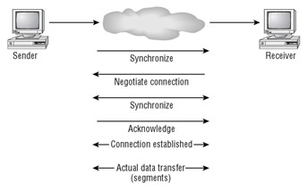
Figure 2.18: Initiating communications using a connection-oriented service
Connectionless services, on the other hand, don’t have error and flow control. They do have one simple advantage: speed. Because connectionless services don’t have the overhead of maintaining the connection, the sacrifice in error control is more than made up for in speed. To make another analogy, connectionless services are similar to a postcard. Each message is considered singular and not related to any other. So, if one part of the message is lost, it can simply be resent.
Name Resolution
The Transport layer also handles logical address–to–logical name resolution. In some protocols, a node address, such as 185.45.2.23, isn’t the best way to reference a host. Some protocol stacks (TCP/IP and IPX/SPX, for example) can use Transport layer logical names for hosts in addition to their Network layer logical addresses. These logical names make it easier for you to find hosts on the network.
At the Transport layer, various protocol stacks implement a protocol to translate Network layer addresses into Transport layer logical names.
Transport Layer Implementations
Before we discuss the other layers of the OSI model, let’s take a look at the IPX/SPX, TCP/IP, and NetBEUI implementations of the Transport layer.
The IPX/SPX Protocol
As far as the connection services of IPX/SPX are concerned, there are two transport protocols: IPX and SPX. IPX is connectionless and thus enjoys the benefits of connectionless transports, including increased speed. SPX, on the other hand, uses connection-oriented services.
IPX/SPX has no name resolution system by default. That functionality is employed when a NetWare server is running Novell Directory Services (NDS) and the NDS directory requester (which runs at the Session, Presentation, and Application layers) can make requests of an NDS database.
The TCP/IP Protocol
Like the IPX/SPX protocol stack, the TCP/IP protocol stack has two transport protocols:
-
Transmission Control Protocol (TCP)
-
User Datagram Protocol (UDP)
TCP is connection-oriented, and UDP is connectionless. Some upper-layer protocols, such as FTP and HTTP, require reliable connection-oriented service and, therefore, use TCP. Other upper-layer protocols, such as Trivial File Transfer Protocol (TFTP) and Network File System (NFS), require increased speed and will trade reliability for that speed. They, therefore, use UDP.
| Note | For network address—to–name resolution, TCP/IP uses Domain Name Services (DNS). It is my belief that the name resolution of the OSI model’s Transport layer was designed for DNS. Many operating systems use DNS for name resolution, but Unix (whose networking is based on TCP/IP) uses DNS almost exclusively. DNS is probably the most cross-platform name resolution method available. Chapter 4 discusses the function and operation of DNS. |
The NetBEUI Implementation
Because it is based on the NetBIOS protocol, NetBEUI (NetBIOS Enhanced User Interface) has datagram support and, thus, has support for connectionless transmission. It doesn’t, however, have support for connection-oriented services. NetBIOS does allow hosts to have logical names (using WINS), but the naming service, as with NDS, functions at the upper layers of the OSI model.
|
|