Objective 2: Design, Implement, Validate, and Baseline the Architecture Software architecture and the related artifacts and activities are also described in Chapter 16. For now, let us simplify architecture to a few key design choices that must be made: -
The most important building blocks of the system, and their interfaces, as well as the decision to build, buy, or reuse some of these building blocks -
A description of how these building blocks will interact at runtime to implement the most important scenarios you have identified -
An implementation and testing of a prototype of this architecture to validate that it does work, that the major technical risks are resolved, and that it has the proper quality attributes: performance, scalability, and cost In the RUP, an architecture is not limited to a paper drawing or a set of blueprints. To validate an architecture, you need more than a review of a paper representation; you need an executable architecture that can be tested to verify that it will address your needs and that it constitutes the proper basis on which to implement the rest of the system. An executable architecture is a partial implementation of the system, built to demonstrate that the architectural design will be able to support the key functionality and, more important, to exhibit the right properties in terms of performance, throughput, capacity, reliability, scalability, and other "-ilities." Establishing an executable architecture allows the complete functional capability of the system to be built on a solid foundation during the Construction phase, without fear of breakage . The executable architecture is built as an evolutionary prototype, with the intention of retaining validated capabilities and those with a high probability of satisfying system requirements when the architecture is mature, thus making them part of the deliverable system. Note that in the layered architecture shown in Figure 7.2, the elements in the lower layers either already exist or will be built during Elaboration; the application layers will be fleshed out with production code during Construction, but will be only partially completed during Elaboration (perhaps only to the extent of constructing the subsystems shells ). Nevertheless, you need to do performance- and load-testing of the critical scenarios by the end of Elaboration, and you should write "stubs" (if not actual application code) to enable this end-to-end testing. Figure 7.2. The Architecture Provides a Skeleton Structure of Your Application. This figure shows one possible representation of the static structure of your system. The architecture consists of the most essential building blocks and their interfaces, and specifies common solutions to frequently encountered problems. It provides a skeleton structure of the application, leaving you to fill in the blanks within a stable and well-defined base . 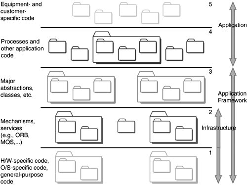 At the end of the Elaboration phase, you baseline your architecture, which means that you make your architecture a stable reference for building the rest of the system. From this point on, you should modify the architecture with care, and only if you have a good reason. This baseline provides some stability for the development team. Note that the larger your team and the more technically complex the project, the more important it is to baseline the architecture. The smaller the team and the less complex your architecture is, the more liberty you can take in modifying the architecture. See Chapter 16 for more information on architecture. Architecture: Defining Subsystems, Key Components , and Their Interfaces At the end of Inception, you produced or at least identified one potential architecture that would allow you to build the system with a reasonable amount of risk and at a reasonable cost. In some cases, you also implemented key elements of the architecture, which we described in the section Objective 3: Determine at Least One Possible Solution, in Chapter 6. At the end of Inception, you had a rough idea of what risks you were facing , especially in the areas of acquisition of technology and reusable assets, such as architectural framework, packaged software, and so on. You left the majority of questions unanswered; other answers were preliminary and left to be finalized during Elaboration. For all these reasons, early in the Elaboration phase you should have a fairly good understanding of what kind of system you are building. Rather than inventing an architecture, you should first envisage using an existing architectural framework to advance the architecture. Maybe there is a commercial framework available (for example, IBM's IAAA for insurance applications), or perhaps you have built this type of system before and can harvest the architecture from previous work. If not, then you need to identify the major building blocks, that is, the subsystems and major components. Potential sources of input are the major abstractions captured in the domain object model or glossary (see Chapter 6). For example, an online transaction system typically requires a component or subsystem [1] that handles each major concept: Shopping Cart, Customer, and Price Promotions. For each identified subsystem or component, describe the key capabilities they need to offer, namely, their interfaces toward the rest of the system. [1] A subsystem corresponds to a component or a collection of components. In parallel with identifying key components and subsystems, you need to survey available assets inside and outside the company. Can you acquire a set of components implementing the concept of Shopping Cart? Do those components satisfy your needs? What are the legal and financial implications? Will the components be maintained as technology and user requirements evolve ? Do we have access to the source code to make necessary changes? Is the code properly documented with supporting guidelines about the components' design and how to use and test them? Use Architecturally Significant
Use Cases to Drive the Architecture During Inception, you should have identified some use cases, perhaps 20 to 30 percent, [2] as being critical to the system (see the section Objective 2: Identify Key System Functionality, in Chapter 6, for more information). They are also likely to be significant in driving the architecture. [2] Note that for some systems, one or two use cases may constitute the core of the application, with a larger number of "supporting use cases" enabling execution of the core use cases. In this situation, fewer than 20 to 30 percent of use cases are architecturally significant, and you would typically implement several scenarios for each core use case. You also need to identify certain elements in the requirementspossibly nonfunctional requirementsthat are difficult, unknown, or at risk, and find use cases (or fragments of use cases) that would illustrate the difficult points and whose implementation would force confrontation and resolution of the risk. These are the technical challenges often relegated to the infrastructure part of the architecture. For example, if there is a very demanding response time requirement, or load requirements, identify one use case (or just one flow of events in one use case) that would illustrate this requirement, together with the expected performance requirement. Other examples would be an error recovery strategy or system startup. Finally, you should identify some use cases that, although not critical nor technically challenging, address some parts of the system not yet covered, so that you will develop a good grasp over the whole architecture of the system by the end of Elaboration. For example, make sure that all your major "business entities" are exercised by at least one of your architecturally significant use cases. You must ensure that the architecture will allow you to deliver all the architecturally significant use cases by designing, implementing, and testing as many of these use cases as necessary to mitigate the risks associated with them (see Figure 7.3). At the same time, you do not want to implement more capabilities than necessary to mitigate the risks, since that would take time from other activities related to risk mitigation , which is one of your primary objectives in Elaboration. Figure 7.3. Architecturally Significant Use Cases Drive the Architecture. For most systems, you can drive out a majority of technical risks and drive the implementation of the architecture by choosing the right 20 to 30 percent of use cases, and designing, implementing, and testing one or two scenarios for each use case. To implement a given use case, you need to identify which software elements are required to provide the functionality of that use case. 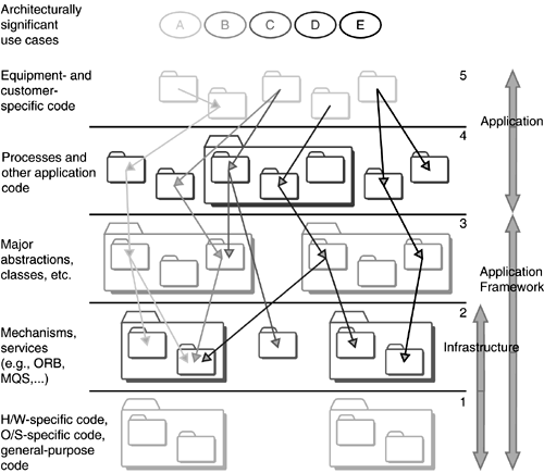 This typically means that, in Elaboration, you should focus on only one or two scenarios or flows of events in a use case: Typically, you would choose the basic flow of events, or "Happy Day" scenario. If necessary, you may also need to implement some scenario(s) involving unexpected events. For example, you might implement one scenario to eliminate risk associated with exception handling, but there would be no point in implementing 10 scenarios to mitigate this same risk. Design Critical Use Cases The design representation of a use case is called use-case realization (see Figure 7.4). It describes how a particular use case is realized within the design model, in terms of collaborating objects. You can divide this work into an analysis section and a design section. The following provides an overview of the five most essentials steps when producing a use-case realization. It should be noted that these steps are helpful for all developers, but you need to determine from project to project how formally you want to document the results of each step, such as on a whiteboard or in a visual modeling tool. See the section Design Use-Case Realizations and Components, in Chapter 17, for a more detailed explanation of these steps. -
Make a preliminary outline of the analysis objects involved in the collaboration. The RUP product provides some excellent guidance to assist those developers inexperienced in object-oriented development in identifying good analysis classes. -
Distribute behavior to analysis classes. That is, specify the overall responsibility of each analysis class so you understand how these classes together can provide the functionality of the use case. -
Detail analysis classes. This helps you understand the responsibility of each analysis class. Review the analysis model to ensure that no two classes provide overlapping functionality and that the relationships between various classes make sense. -
Design use cases. In other words, specify in exactly what order, and how, each design class will communicate with other design classes to provide the architecturally significant parts of the use-case functionality. This way of partitioning the functionality of a use case into a set of design elements that communicate with each other can be used for object-oriented or nonobject-oriented systems. -
Refine analysis classes into design classes. In many cases, several design classes implement one analysis class. Detail each design class by specifying operations and attributes, review the design model to ensure that you have not duplicated functionality across several classes, and see that all relationships between classes make sense. Figure 7.4. An Example Sequence Diagram. A use-case realization shows how your design elements are collaborating to provide the functionality of the architecturally significant parts of the use case. One way to show this collaboration is through a sequence diagram. 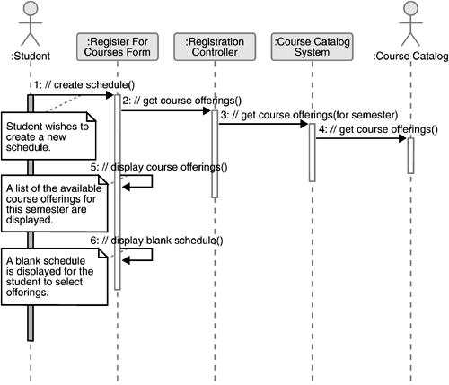 Simple use cases with limited sequencing, especially if implemented via a powerful programming language (such as Visual Basic or another fourth-generation language), typically do not require all these steps, especially step 4. Consolidate and Package Identified Classes The next step is to group the identified classes into appropriate subsystems. The architecture team will already have identified some of the subsystems (see the earlier section Architecture: Defining Subsystems, Key Components, and Their Interfaces). Some guidelines for packaging classes follow: -
Localize the impact of future changes by grouping classes that are likely to change together into the same subsystem . (See Figure 7.5.) For example, if you expect the interface for a certain actor to change radically , place all the classes implementing the interface for that actor in the same subsystem. Figure 7.5. Packaging Should Localize Impact of Change. You can localize the impact of change by placing all classes that are dependent on a certain database, or the interface for an actor, in the same subsystem. 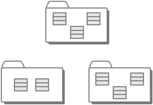 -
Enforce certain rules of visibility. For example, enforce rules that define boundaries between the multiple tiers in a client/server application. You do not want to package classes from different layers into the same subsystem. -
Consider packaging classes according to how you will configure the future application/product. This means that you can assemble various configurations of the final application by choosing to include or exclude various subsystems. For more considerations regarding how to package classes, see Guidelines: Design Package in the RUP product. Ensure Architectural Coverage One important objective in building the executable architecture is to ensure that it includes use cases touching on all major areas of the system. This ensures that a seemingly straightforward area of the system does not hide unexpected problems, an issue of particular importance when building unprecedented systems. Once you have consolidated the packaging and detailed the use-case realizations, you need to confirm that all areas of your system are covered. If, toward the end of Elaboration you discover "untouched" areas of the system, you should identify additional scenarios to implement in order to ensure architectural coverage (see Figure 7.6). This is part of your risk mitigation strategy to minimize unexpected issues later. A good coverage will also ensure that your estimates are valid. Figure 7.6. Architectural Coverage. Use case E may not be considered architecturally significant, but it is added to the list of use cases to design, implement, and test to ensure that you have architectural coverage for otherwise untouched parts of the architecture. 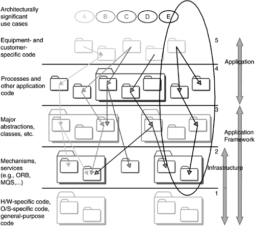 Architectural coverage is typically more a concern for larger projects than for smaller projects and can often be disregarded by small projects. Design the Database Many systems have a database, and you need to understand how persistent data is to be stored and retrieved. You can find comprehensive guidance within the Rational Unified Process in the area of database design (see the Database Design activity and the Data Model guidelines in the RUP product). You can also find useful information in Ambler 2000. Outline Concurrency, Processes, Threads, and Physical Distribution Next, you need to describe the run-time architecture in terms of concurrency, processes, threads, interprocess communication, and so on. For distributed systems, you need to describe the distribution by outlining the physical nodes. This description includes defining the network configuration and allocating processes to nodes. We discuss this issue in more detail in Chapter 16. Identify Architectural Mechanisms Architectural mechanisms represent common concrete solutions to frequently encountered problems (see Figure 7.7). They are architectural patterns, providing standard solutions to problems such as garbage collection, persistent storage, list management, "shopping cart" implementation, or communication with external systems through a certain protocol. Figure 7.7. Architectural Mechanisms. Architectural mechanisms provide solutions to common problems. You may have one or several mechanisms for persistency, communication, parsing, and authentication; each one may be used many times in the system. 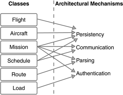 By designing, implementing, testing, and documenting architectural mechanisms, you can solve the most common and difficult problems once, and then all team members can take advantage of these ready-made solutions whenever they need them. This approach allows developers to be more productive, and it greatly speeds up the work in the Construction phase, when typically more people join the project. We also discuss architectural mechanisms in Chapter 16. Implement Critical Scenarios Each design class provides a specification for code. In most cases, implementing the class is done iteratively as the class is designed. You design a little, implement what you design, detect deficiencies, and then improve the design. As you implement components, you need to unit-test the component to ensure that it performs according to specifications and that you have not introduced memory leaks or performance bottlenecks (see the section Developer Testing, in Chapter 17, for more details). When both designing and implementing a class, you need to consider how to test the system. You might also need to design and implement test classes representing test drivers and interfaces to automated test tools. Integrate Components When doing iterative development, it becomes increasingly complex to plan builds and integration testing. In parallel with identifying analysis classes, you need to determine in what order you will integrate what components , and as you do class design, you need to verify that you design and implement the functionality necessary to integrate and compile your evolving system for testing. Integration is a continuous activity. If your iterations are four weeks long, for example, you should typically produce a build daily or at least twice weekly. As the size of your system and your team grow, you may have to increase the interval between builds (as well as the iteration length). Note that the level of support you have for configuration management, including automated build management, highly impacts your ability to plan and frequently create builds. Test Critical Scenarios Testing is an extremely important aspect of Elaboration. The best way to verify that you have mitigated risk is to test the executable architecture. Among other things, you want to verify that -
Critical scenarios have been properly implemented and offer the expected functionality. -
The architecture provides sufficient performance. Typically there are a couple of scenarios critical to performance, and these need to be performance-tested. For an Online Transaction System, you might need to verify that the use case Check Out performs sufficiently. If it does not, then you may have to rework the architecture. -
The architecture can support necessary load . Usually, there is a small set of scenarios that are critical to load, and these need to be load-tested. For an Online Transaction System, you might need to verify that the use cases Browse Catalog, Put Item in Cart, and Check Out can carry a load of 1,000 simultaneous users. If it can't, then you might have to revisit various architectural decisions. -
Interfaces with external systems work as expected . Does the API work as expected? What about performance and synchronization issues? -
Any other requirements in the supplementary specification (nonfunctional requirements) that are not captured above are tested. Failover, reconfiguration, and recovery scenarios might fit into this category. The supplementary specification is an important source of requirements that need to be tested from an architectural viewpoint and might require you to construct special scenarios for effective testing. Some of this testing can be automated with test tools, allowing you to see whether you lack the proper test tools or lack competency with the tools you have. In this way, the iterative approach forces you to "test" your test capabilities early on so that you can fix any issues before it is too late. For more information on testing, see Chapter 18. What Is Left to Do? The list of activities we've just covered is quite comprehensive, so what is left to do? Well, keep in mind that although you have completed many types of project activities, you have only designed, implemented, and tested 10 to 20 percent of the system. You partially implemented only 20 to 30 percent of the use cases, and then implemented only one or two Happy Day scenarios for each of those use cases. You may also have implemented some architecturally significant alternative flows of events, among others, to test your exception mechanisms. But overall, the majority of the coding effort for the project will deal with alternative or unexpected user interaction and exception handling. So, in Elaboration, you did a little of everything, but you still have roughly 80 percent of code left to do in the following lifecycle phases of Construction and Transition. On the positive side, however, the code you did implement and test represents the most difficult parts of the system, and it allows you to mitigate the vast majority of risks in your project. For each of our three example projects, you do the following: -
Project Ganymede, a small green-field project:  The team evolves the functional prototype built in Inception into a more complete executable architecture, allowing them to showcase some of the key functionality (when in the hands of developers, only certain very well-defined scenarios are supported) and, more important, confirm that the architecture supports the necessary performance, scalability, dependability , and so on. The architecture was tested and used as a baseline for further work. The team evolves the functional prototype built in Inception into a more complete executable architecture, allowing them to showcase some of the key functionality (when in the hands of developers, only certain very well-defined scenarios are supported) and, more important, confirm that the architecture supports the necessary performance, scalability, dependability , and so on. The architecture was tested and used as a baseline for further work. -
Project Mars, a large green-field project:  The team evolved the conceptual prototype built in Inception into a more complete executable architecture, allowing them to showcase some of the key functionality (when in the hands of developers, only certain very well-defined scenarios are supported) and, more important, to confirm that the architecture supports the necessary performance, scalability, dependability, and so on. Since performance and scalability were a big issue, a fair amount of time was spent on doing performance- and load-testing of the architecture. This exposed a number of issues with the architecture. A lot of rework was done, which saved a great deal of time down the road. The revised architecture was used as a baseline for further work. The architect walked through the architecture with the entire team to ensure that everybody understood the architecture. The team evolved the conceptual prototype built in Inception into a more complete executable architecture, allowing them to showcase some of the key functionality (when in the hands of developers, only certain very well-defined scenarios are supported) and, more important, to confirm that the architecture supports the necessary performance, scalability, dependability, and so on. Since performance and scalability were a big issue, a fair amount of time was spent on doing performance- and load-testing of the architecture. This exposed a number of issues with the architecture. A lot of rework was done, which saved a great deal of time down the road. The revised architecture was used as a baseline for further work. The architect walked through the architecture with the entire team to ensure that everybody understood the architecture. -
Project Jupiter, a second generation of a large project:  The team could rapidly go through Elaboration because they did not face major technical risks. Technical risks were mitigated by implementing and trying out some of the new technology. Partial implementations of a few key use cases were done to verify that the new functionality would not regress the architecture. The team could rapidly go through Elaboration because they did not face major technical risks. Technical risks were mitigated by implementing and trying out some of the new technology. Partial implementations of a few key use cases were done to verify that the new functionality would not regress the architecture. |


