Setting Up the TL Pipeline Matrices
This section discusses the details of building the three transformation matrices—world, view, and projection—that must be specified for the T&L pipeline.
The World Matrix
Recall that the world matrix transforms coordinates from model space (in which vertices are defined relative to the model's local origin) to world space (in which vertices are defined relative to an origin that is common to every object in the scene). If the term world matrix seems ambiguous to you, think of this matrix as a "local-to-world matrix." Because you'll probably render several objects in a scene, each with its own local coordinate space, you'll change the world matrix several times in the process of rendering a single frame. (The relationship between the world coordinate system and the model's local coordinate system was shown in Figure 5-3.)
You create the world matrix as you do all transformations: using a combination of transformation matrices to produce a final matrix that performs all the transformations each separate matrix produces. In the code below, I show how to create an example world matrix and then modify it with additional matrices to translate a model into world space. The code then rotates the model to place it in its final orientation.
If a model is at the world origin and its local coordinate axes are oriented the same as world space, the world matrix is just the identity matrix. Usually the world matrix is a combination of a translation into world space and potentially one or more rotations to turn the model to its proper position.
The variables for defining the matrix are shown below. The D3DMATRIX type used for the matrices is declared in Direct3D as a two-dimensional array containing a 4 × 4 matrix.
HRESULT hr; D3DMATRIX matWorld, // World matrix being constructed matTemp, // Temporary matrix for rotations matRot; // Final rotation matrix (applied to // matWorld) // Using the left-to-right order of matrix concatenation, // apply the translation to the object's world position // before applying the rotations. D3DUtil_SetTranslateMatrix(matWorld, m_vPos); D3DUtil_SetIdentityMatrix(matRot); // // Now apply the orientation variables to the // world matrix. // if(m_fPitch || m_fYaw || m_fRoll) { // Produce and combine the rotation matrices. D3DUtil_SetRotateXMatrix(matTemp, m_fPitch); // Pitch D3DMath_MatrixMultiply(matRot,matRot,matTemp); D3DUtil_SetRotateYMatrix(matTemp, m_fYaw); // Yaw D3DMath_MatrixMultiply(matRot,matRot,matTemp); D3DUtil_SetRotateZMatrix(matTemp, m_fRoll); // Roll D3DMath_MatrixMultiply(matRot,matRot,matTemp); // Apply the rotation matrices to complete the // world matrix. D3DMath_MatrixMultiply(matWorld, matRot, matWorld); } hr = lpDev->SetTransform(D3DTRANSFORMSTATE_WORLD, &matWorld); |
This code block calls the D3DUtil_SetTranslateMatrix routine, passing in the viewpoint. The routine then calls the D3DUtil_SetIdentityMatrix routine to initialize the matrix with the identity matrix. This identity matrix is organized as an all-zero matrix with 1s along the diagonal, as shown here:

The identity matrix represents a "no-op" transformation; that is, a point transformed through an identity matrix has the same coordinates coming out as going in.
inline VOID D3DUtil_SetIdentityMatrix( D3DMATRIX& m ) { m._12 = m._13 = m._14 = m._21 = m._23 = m._24 = 0.0f; m._31 = m._32 = m._34 = m._41 = m._42 = m._43 = 0.0f; m._11 = m._22 = m._33 = m._44 = 1.0f; } |
You should also use routines to enable your program to perform rotations, translations, and scaling in the x, y, and z axes. A translation transformation translates the point (x, y, z) to a new point (x', y', z') using the following formula:

D3DUtil_SetTranslateMatrix, which takes the amount to translate along the x, y, and z axes (tx, ty, tz), and creates a translation matrix, is defined as follows:
inline VOID D3DUtil_SetTranslateMatrix( D3DMATRIX& m, FLOAT tx, FLOAT ty, FLOAT tz ) { D3DUtil_SetIdentityMatrix( m ); m._41 = tx; m._42 = ty; m._43 = tz; } inline VOID D3DUtil_SetTranslateMatrix( D3DMATRIX& m, D3DVECTOR& v ) { D3DUtil_SetTranslateMatrix( m, v.x, v.y, v.z ); } |
Once the translation matrix is filled, you could multiply it with the current world matrix to translate it. The following call does this for you:
D3DMath_MatrixMultiply (WorldMatrix, TranslateMatrix, WorldMatrix); |
The D3DMath_MatrixMultiply routine multiplies two matrices together and places the result into a third matrix. This call will multiply the world matrix by the translation matrix to move the point along all three axes the distance specified in the x, y, and z directions and place the result back into the world matrix. When you're working with matrices, you need to remember that matrix concatenation/multiplication isn't commutative. Because of this, you need to make sure your parameters are in the right order when calling D3DMath_MatrixMultiply and when building up matrices from transformations in general.
The D3DMath_MatrixMultiply routine is defined as follows:
VOID D3DMath_MatrixMultiply( D3DMATRIX& q, D3DMATRIX& a, D3DMATRIX& b ) { FLOAT* pA = (FLOAT*)&a; FLOAT* pB = (FLOAT*)&b; FLOAT pM[16]; ZeroMemory( pM, sizeof(D3DMATRIX) ); for( WORD i=0; i<4; i++ ) for( WORD j=0; j<4; j++ ) for( WORD k=0; k<4; k++ ) pM[4*i+j] += pA[4*i+k] * pB[4*k+j]; memcpy( &q, pM, sizeof(D3DMATRIX) ); } |
One additional useful helper function for multiplying a vertex by a matrix, D3DMath_VertexMatrixMultiply, follows.
//-------------------------------------------------------------------- // Name: D3DMath_VertexMatrixMultiply // Desc: Multiplies a vertex by a matrix //-------------------------------------------------------------------- HRESULT D3DMath_VertexMatrixMultiply( D3DVERTEX& vDest, D3DVERTEX& vSrc, D3DMATRIX& mat) { HRESULT hr; D3DVECTOR* pSrcVec = (D3DVECTOR*)&vSrc.x; D3DVECTOR* pDestVec = (D3DVECTOR*)&vDest.x; if( SUCCEEDED( hr = D3DMath_VectorMatrixMultiply( *pDestVec, *pSrcVec, mat ) ) ) { pSrcVec = (D3DVECTOR*)&vSrc.nx; pDestVec = (D3DVECTOR*)&vDest.nx; hr = D3DMath_VectorMatrixMultiply( *pDestVec, *pSrcVec, mat ); } return hr; } |
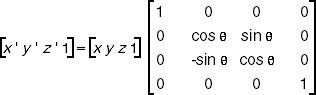
Once you've set up the matrix to translate the desired distances, you need to add the rotations you want. In the code for this book, we just need to rotate about the y-axis to orient ourselves properly to our 3D world if we're just walking straight or driving on a flat surface. If you need to orient your objects differently (which often happens if the 3D tool you use to create 3D objects uses a different orientation than the ones used here), you rotate about the x and z axes. Because you'll want to handle all three axes sooner or later, I show the matrices and list the routines for performing rotations about the x, y, and z axes.
The matrix to perform a rotation about the x-axis, where θ equals the amount you want to rotate about this axis, follows:
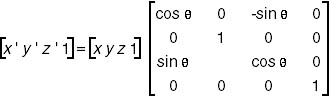
The matrix to perform a rotation about the y-axis, where θ equals the amount you want to rotate about this axis, looks like this:
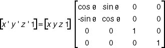
To perform a rotation about the z-axis, where θ equals the amount you want to rotate about this axis, use this matrix:
Once you've defined the world transformation matrix, you need to call the IDirect3DDevice7::SetTransform method to set it, specifying the D3DTRANSFORMSTATE_WORLD flag in the first parameter.
This method uses the D3DTRANSFORMSTATETYPE enumerated type to describe the transformation state for the D3DOP_STATETRANSFORM opcode in the D3DOPCODE enumerated type, which is organized as follows:
typedef enum _D3DTRANSFORMSTATETYPE { D3DTRANSFORMSTATE_WORLD = 1, D3DTRANSFORMSTATE_VIEW = 2, D3DTRANSFORMSTATE_PROJECTION = 3, D3DTRANSFORMSTATE_FORCE_DWORD = 0x7fffffff, } D3DTRANSFORMSTATETYPE; |
These members are defined as follows:
- D3DTRANSFORMSTATE_WORLD, D3DTRANSFORMSTATE_VIEW, and D3DTRANSFORMSTATE_PROJECTION Used to define the matrices for world, view, and projection transformations. The default value for each member is NULL, indicating the identity matrices.
- D3DTRANSFORMSTATE_FORCE_DWORD Used to force this enumerated type to 32 bits.
The View Matrix
The view transformation transforms the vertices from world space into camera space. The camera, which represents the viewer, is positioned at the origin looking in the positive z direction (because of the left-handed coordinate system Direct3D uses) in camera space. The view matrix is used to translate and rotate the objects in the 3D world around the camera's position and orientation. (Again, the camera's position is the origin.)
You can create a view matrix in a number of ways. The approach I often use is to directly create the composite (a single matrix derived from multiple transformation matrices) view matrix. By taking the camera's world space position and a position in the scene to look at, you can have vectors computed to define the orientation of the camera space coordinate axes. The camera's position is subtracted from the position of the viewer, and the resulting vector is used as the camera's direction vector (n). The cross product of this vector and the y-axis of the world space is computed and normalized to produce a "right" vector (u).
The cross product of the vectors (u and n) is then computed to obtain an up vector (v). The three vectors—up, right, and view—define the orientation of the coordinate axes for the camera space in terms of the world space. You compute the x, y, and z translation factors by taking the negative of the dot product between the camera position and the u, v, and n vectors.
You then place these values into the following matrix, where c is the camera's world space position, to generate the view matrix. This matrix translates and rotates the vertices from world space to camera space:

Although the above computation might seem complicated, the code to perform these tasks is fairly straightforward. Best of all, you can reuse the code for all your applications.
This math is all done for you by the following function from the Direct3D Framework:
HRESULT D3DUtil_SetViewMatrix( D3DMATRIX& mat, D3DVECTOR& vFrom, D3DVECTOR& vAt, D3DVECTOR& vUp ); |
The Projection Matrix
The final matrix you need to create is the projection matrix, which is used to control how the viewer sees the contents of the 3D world. The projection matrix works like a lens on a camera. To produce this matrix, you usually create a scale and perspective projection.
The code below sets up a projection matrix, taking the front and back clipping planes and the field of view in radians. The IDirect3DDevice7::SetTransform method is then called to set the projection transformation, just as for the world and view transformations, except this time D3DTRANSFORMSTATE_PROJECTION is specified in the first parameter.
Here are the calls and the routine to set up the matrix and use this method:
D3DUtil_SetProjectionMatrix( matProj, 1.57f, 1.0f, 1.0f, 100.0f ); m_pd3dDevice->SetTransform( D3DTRANSFORMSTATE_PROJECTION, &matProj ); |
EAN: 2147483647
Pages: 131