SSIS Review
Many of you have practical, learn-on-the-go experience using SSIS, and are looking to this book to take your knowledge to the next level and to fill in any knowledge gaps. Others of you have a good book knowledge of SSIS and want to extend your skills. And there may be those of you (like us) who like to dive right in, skip the intro books, and go right for the expert material.
To set the stage and provide a common starting point, we will walk you through a package creation that involves many of the SSIS key concepts. It’s impossible to wrap all the SSIS functionality into this one example, but you will get a good review of the basic features. If you feel you already know how to use the basic SSIS features comfortably, feel free to skip this section. The ensuing discussions, however, assume that you know some of these basic concepts and will not walk you through these steps again. You should be familiar with some basics such as how to create a solution. This example assumes some SSIS background, so if you need a more fundamental review, see one of the starter SSIS books available such as Professional SQL Server 2005 Integration Services (Wiley Publishing, 2006).
In this package creation walk-through, you will start by developing a simple package Data Flow that pulls a limited range of data (by using package variables) from a source and adds some data transformation steps. Since SSIS includes more than just processing data, you will then be working with the control flow and creating complementary tasks and containers with Precedence Constraints to control what happens in what order in this example. The final step is executing the package.
To begin, first start by opening the Business Intelligence Development Studio (BIDS) tool and creating a new SSIS project called ExpertSSIS. Then, rename the default package that is created (Package.dtsx) to Chapter1.dtsx. Confirm that you’d like to rename the package object as well.
Creating a Connection Manager
After creating the package, you can create the first connection manager. Right-click in the Connection Manager pane at the bottom of the package editor and select New OLE DB Connection. On the Configure OLE DB Connection Manager screen, if you do not have an AdventureWorks connection in the Data Connections list, click New. Type localhost for the Server Name property, and select AdventureWorks from the Database drop-down box. Click OK to save the connection, and click OK again when you have the localhost.AdventureWorks connection selected. Right-click the newly created localhost.AdventureWorks connection manager and rename it to AdventureWorks.
Using the Control Flow
The Control Flow tab is where you perform the package’s workflow. For example, you may decide to receive a file through FTP, transform the data within the file, and then archive the file. In that example, you would have three tasks:
-
An FTP Task
-
A Data Flow Task
-
A File System Task
If you need help with the configuration of these tasks, consult one of the starter books such as the Professional SQL Server 2005 Integration Services book. Configuration of these tasks is not addressed in this book. Instead, we will concentrate on how to build solutions using the tasks.
In the Control Flow tab of the example package, drag over a single Data Flow Task onto the design pane. This Data Flow Task will perform the transformation of data. Rename the task Create Product File by right-clicking the task and choosing Rename.
Select Variables from the SSIS menu, which opens the Variables window. Create three variables in the window:
-
RowCount as an int32 data type
-
StartDate as a datetime data type
-
EndDate as a datetime data type
Create the default value of the StartDate to some date in 2001, and set the default value of the EndDate variable to some date in 2007.
Working in the Data Flow
When you double-click on the Data Flow Task, you are taken to the Data Flow tab. The Data Flow Task streams data from nearly any structured, semi-structured, or non-structured source to nearly any destination. In this case, you will pull data from a SQL Server source, transform the data by using a number of transformation components, and then write the result to a text file. Figure 1-4 shows the Data Flow tab in a package without the components defined yet. Notice that the toolbox contains adapters and transformations that you will be using throughout this book.
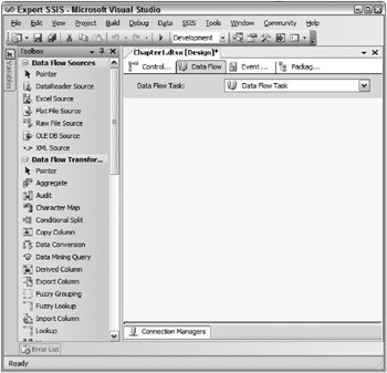
Figure 1-4: The Data Flow Task
Drag over an OLE DB Source from the toolbox. Name the source Products. Double-click the source to configure it, as shown in Figure 1-5. Ensure that you’re pointing to the AdventureWorks connection manager and then change the Data access mode entry to SQL command. Enter the following command in the SQL command text window:
SELECT * FROM Production.Product WHERE SellStartDate > ? and SellStartDate < ?
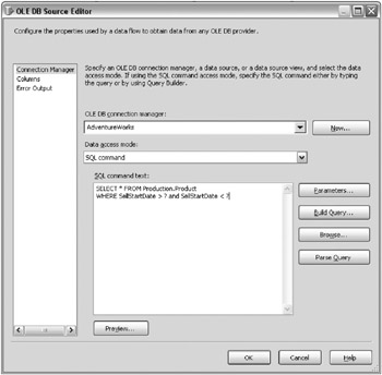
Figure 1-5: Configuring the source
The query returns all the products that are within a certain date range. The question marks represent parameter values that will be passed in through a variable. Click the Parameters button to map the question marks to the variables you’ve already created. Each question mark parameter you see in the Set Query Parameters window is ordinal (see Figure 1-6). So, the first question mark is represented by Parameter0, the second by Parameter1, and so on. Map Paramater0 to User::StartDate and Parameter1 to User::EndDate. Click OK to go back to the Data Flow tab.
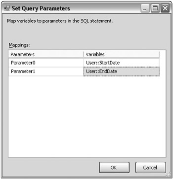
Figure 1-6: Set Query Parameters window
Next, drag a Lookup transform onto the design pane. Connect the Product source to the Lookup transform by dragging the green arrow from the source to the transform. Name the Lookup transform Find Model Name.
Open (by double-clicking) the Lookup transform to configure it. Point the transform to the AdventureWorks connection manager and to the [Production].[ProductModel] table by using the appropriate drop-down list boxes as shown in Figure 1-7. In the Lookup configuration dialog box, select the Columns tab and you’ll see that there are more arrows connecting the input to the lookup columns than you actually need. Right-click each arrow and click Delete until the only one remaining is the arrow that connects ProductModelID on each side, as shown in Figure 1-7. Click Name from the Available Lookup Columns table and then type the Output Alias of ModelName.
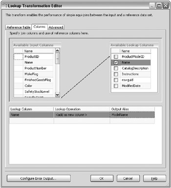
Figure 1-7: Deleting arrows
Finally, click the Configure Error Output button. Change the Error column from Fail Component to Ignore Failure. Click OK twice to exit the transform configuration.
As a review of the Lookup Transformation Editor, the first tab tells the component where to find the reference (lookup) data. The second tab tells the component which fields it should try to match in the source and reference data sets-the lookup column is the value you want to retrieve. Finally, the error output configuration tells the Lookup what to do with the row in the case of failure.
What this transform does for you now that it is completely configured is try to find the name of the model based on where the ProductModelID on the source matches the reference table. If it can’t find a match, an error occurs. However, you have configured the transform to ignore the error, and so the ModelName column will now contain a NULL value if the match is not found. You could have also told the transform to redirect rows where it can’t find a match to another output, which would be the red arrow coming out of the transform. At that point, you could have written those rows to a queue, or performed some additional cleanup.
| Important | In some destination table loading (and definitely in data warehouse dimension table loading), if you can’t find a matching record in the Lookup, then an “unknown value” needs to be inserted (a NULL value in many cases is not acceptable). A more elegant way to do this is through ignoring errors and using a derived column transform to replace NULLs with a default value. |
Drag a Derived Column transform onto the data flow and connect the output of the Lookup transform to the Derived Column. Name the Derived Column transform Assign Default Values and Price. In this scenario, you want to give a special customer discount on products that your company makes (the MakeFlag column lets you know if you made the product). There are two ways to perform this conditional assignment:
-
Use a Conditional Split transformation and then a Derived Column transformation
-
Use the Derived Column transformation and utilize the SSIS expression language to perform conditional coding
Open the Derived Column Transformation Editor (shown in Figure 1-8) in the data flow to configure the transform. For the first derived column name, you will want to replace the NULL values in ModelName with the word Unknown. You will want this to replace the existing column of ModelName by selecting Replace 'ModelName' from the Derived Column drop-down box. To solve a business requirement of not having NULLs in your warehouse, you can use the conditional operator of a question mark as shown here for the Expression column:
ISNULL([ModelName]) == TRUE ? "Unknown" : [ModelName]
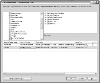
Figure 1-8: Derived Column Transformation Editor
Another entry in the Derived Column Transformation Editor will satisfy requirements for the discounted product price for products that you make. Again, you will want to change the Derived Column drop-down box to Replace 'ListPrice'. This time, the conditional logic will be slightly different. You’re going to give a 10 percent discount on any product that you make, so you’ll read the MakeFlag column. If it’s set to true, then you’ll discount. Otherwise, you’ll use the existing price in the column. The code will look like this:
[MakeFlag] == TRUE ? [ListPrice] * 0.9 : [ListPrice]
In both of these columns, the == TRUE snippet of code is optional, but is useful for full self-documentation of code. If you were to have the statement ISNULL([ModelName]), it would essentially mean the same thing as this code. Also note that the columns and variables in the expression language are all case-sensitive.
Your final screen should look like Figure 1-8. Click OK to exit the editor.
Lastly, you want to audit how many rows you are about to write to the flat file. To do this, you can drag the Row Count transform onto the design pane. Connect the transform downstream of the Derived Column transform. Rename the Row Count transform to Count Inserts and double-click it to configure the transform.
Set the VariableName property in the Component Properties tab to RowCount. The variable name is case-sensitive. Because the last row is written through the transform, it is counted and logged to the variable for future use. A typical use for this transform is to count the number of rows transformed and write the result into an audit table.
With the data now transformed, you’re ready to write the data to the extract file for use by another party (such as a business partner or another department). Drag over a Flat File Destination and rename it to Partner Extract. Double-click the destination to configure it. When the destination opens, click New to create a new connection manager. When the Flat File Format dialog box opens, select Delimited and click OK.
You’re now taken to the Flat File Connection Manager Editor (shown in Figure 1-9). Name the connection manager Partner Extract and type C:\ExpertSSIS\partnerextract.txt for the file name (the directory, of course, must already be created). Select the Column names in the first data row check box.
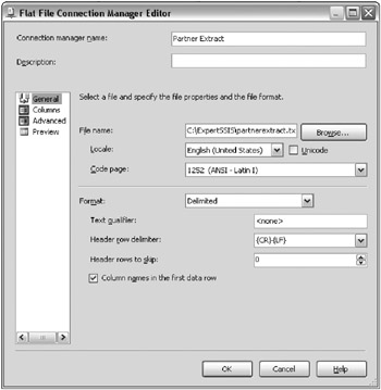
Figure 1-9: Flat File Connection Manager Editor
Next, go to the Columns page. In this page, make the column delimiter a vertical bar (|) by changing the Column delimiter drop-down box as shown in Figure 1-10.
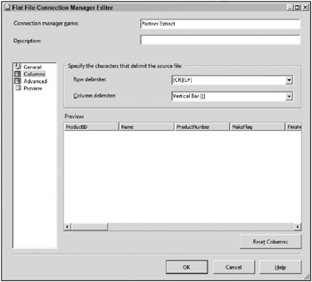
Figure 1-10: Changing the Column delimiter
Click OK to exit the editor and return to the Flat File Destination Editor. Click the Mappings page to confirm the data mappings and then click OK. Each time the data flow is run, the extract file is overwritten.
Precedence Constraints
Precedence constraints are the conductor for your workflow. They dictate which tasks will execute and in what order. Precedence constraints appear as lines in the control flow that connect one or more tasks together. The green arrow represents On Success and means that the second (or downstream) task will only execute if the first (or upstream) task or set of tasks executes successfully. The blue arrow represents On Completion and means that regardless of whether the upstream task completes successfully or fails, the downstream task will execute. This is useful for a clean-up task, for example. The red arrow represents On Failure and means that the downstream task will execute only if the upstream task fails.
You can also place expressions on the precedence constraint. With this functionality, you can put code on the constraint that states that the expressions must be true, and optionally the constraint must be true as well. These are useful if you want to add conditions into your control flow.
Returning to the example application, go to the Control Flow tab and drag over a Script Task onto the design pane. Rename the task to Stub Code and drag the green arrow out of the Data Flow Task onto the Script Task. Drag over one more Script Task and call it Stub Code 2. Drag the green arrow out of both of the other tasks onto Stub Code 2. These tasks will act only as placeholders for future code. The control flow should now look like Figure 1-11. Currently, Stub Code 2 will execute only after the first two tasks successfully execute.
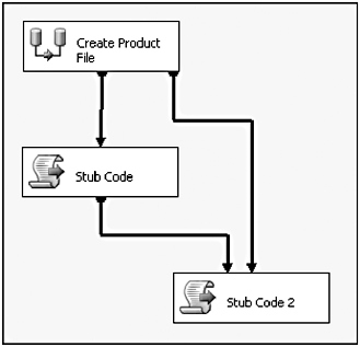
Figure 1-11: Current control flow
Double-click the precedence constraint between the Data Flow Task (named Create Product File) and the Stub Code Script Task. Change the Evaluation operation option to Expression and Constraint. The value should remain Success and the Expression should read @intCount > 400, as shown in Figure 1-12. Click the Test button to make sure you have valid syntax. As in the rest of SSIS, variable names are always case-sensitive. This configuration means that the Stub Code Task will execute if and only if both the Data Flow Task succeeds and it transforms more than 400 records (read from the Row Count transform in the data flow).
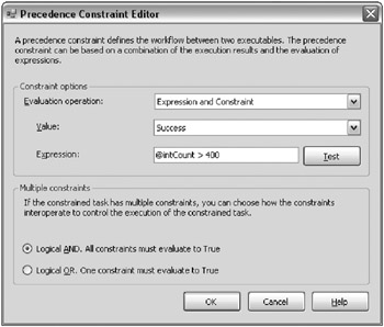
Figure 1-12: Success value and expression
In this configuration, if there are less than 400 rows transformed, Stub Code 2 will never execute, even though there’s an On Success precedence constraint between the Data Flow Task and the task. This is because you have a Logical And condition on the Stub Task 2 when multiple constraints are connected into it. This means that both the Data Flow Task and the Stub Code Task must successfully execute before the Stub Code 2 Task executes. You may also want the Stub Code 2 Task to execute when either task successfully completes. To do this, you can double-click either of the precedence constraints that connect to Stub Code 2 and change the Multiple constraints option to Logical OR.
Package Execution
Notice that after you change the constraint type, the solid green line turns into a dotted green line as shown in Figure 1-13. At this point, you’re ready to execute the package by right-clicking the package in the Solution Explorer and clicking Execute Package. If you transformed less the 400 records, the package will look like Figure 1-13, where the Data Flow and Stub Code 2 executes.
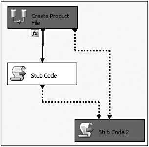
Figure 1-13: Solid line changing to dotted line
One way you can see how many rows transformed is to go to the Data Flow tab before stopping the package. You’ll see how many rows transformed through the pipeline (shown in Figure 1-14). You can stop the package by clicking the Stop button (the square blue button on the BIDS toolbar) or by clicking Stop Debugging from the Debug menu. If you have any problems executing the package, you can go to the Progress tab to see the error. After you stop the package, the Progress tab turns into the Execution Results tab, which shows the results of the last package execution.
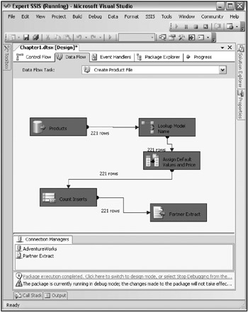
Figure 1-14: Viewing how many rows transformed through the pipeline
When you execute a package from the BIDS environment where you can see the results visually, you’re executing the package in debug mode. You can also execute the package without debugging by selecting Start Without Debugging from the Debug menu. This performs slightly faster than executing a package from within debug mode, but it’s much harder to troubleshoot an issue.
Executing a package outside of debug mode opens a command prompt, as shown in Figure 1-15, and runs the dtexec.exe utility. You can tell the package successfully executed by the DTSER_SUCCESS code at the end of the execution. You can also see how fast each task and container executed after each item completes in the command window, or how fast the entire package executed, which is shown at the bottom of the command line execution output (in the command window).
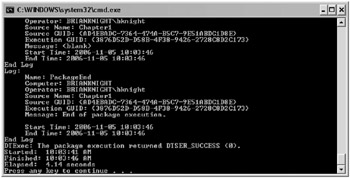
Figure 1-15: Execution of the dtexec.exe utility
Containers
With the package now complete, you could make it more advanced and cleaner by wrapping certain functionalities in containers. Containers help you group tasks logically together but also have other functionalities. There are three types of containers that you’ll typically need to be concerned with:
-
Sequence
-
ForLoop
-
ForEach Loop
There is actually a fourth type of container called TaskHost, which wraps every task behind the scenes.
The Sequence container group simply groups tasks visually inside a collapsible box, as shown in Figure 1-16. In this figure, Prepare OS and Set Variables will execute sequentially before allowing the Create Product File Task to execute. Sequence containers help you to clean up and abstract the details of your control flow, since you can minimize a container if you don’t care about the complexity of what’s happening inside the container. Events bubble up to the container, so if a failure occurs in a task, it will fail the parent container by default.
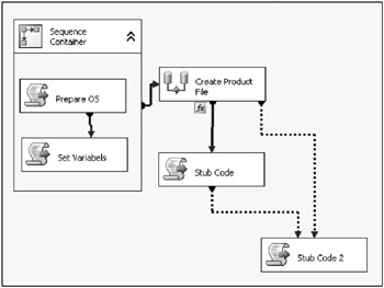
Figure 1-16: Sequence container grouping tasks together into a box
Sequence containers aren’t just for looks though. You can also isolate transactions to a container so that if a problem occurs in a data task, you can roll back any other data action that had occurred in the container if it’s participating in the container transaction. You can also log or create event handlers on anything in the container.
ForLoop containers enable you to do a Do...While loop inside the control flow. Any task inside the ForLoop container will loop continuously until the while condition is no longer met. This comes in handy if you want to continuously loop until a variable is set to TRUE.
One of the most important types of container is the ForEach Loop container. With this container, you specify a collection of items to enumerate through, and then any items inside the container will loop until SSIS enumerates to the end of the collection. Out of the box, you can enumerate through a collection of files in a directory, records in a table, or a list of items that you type. There are other types of enumerators that you can specify, and you can even write your own enumerator.
It’s also important to note that after you place a set of tasks inside a container, they can only relate through precedence constraints to other tasks in the container. An individual task inside the container can never relate directly to anything else outside the container. The last thing to point out about containers is that you can embed containers inside containers.
Review Conclusion
Even though this walk-through only highlights the data flow and control flow, you still can see that SSIS is a broad-featured tool capable of a lot of diverse applications.
In the end, it’s all about the data-ensuring that the information is handled in the right way to meet your needs. This does not minimize the supporting requirements such as transactions handling, deployment, and execution monitoring, because these are important pieces to building a stable SSIS environment. When you take the primary data processing tasks and add in administration, error handling, scalability, testing, and deployment, the result is like juggling spinning plates. It’s no wonder why ETL consumes up to 70 percent of an enterprise data warehouse development effort.
You may know this already: If you can reduce the amount of time it takes to build an ETL solution (including the supporting architecture), then your projects are in a better position for success. This is the value proposition of SSIS-a tool that can integrate all the needed features for a complete ETL system in an architecture that is supportable and extendable. With the right tool and right architecture, more time can be spent on testing the data and presenting the data to the users.
EAN: 2147483647
Pages: 111