Advanced Drawing
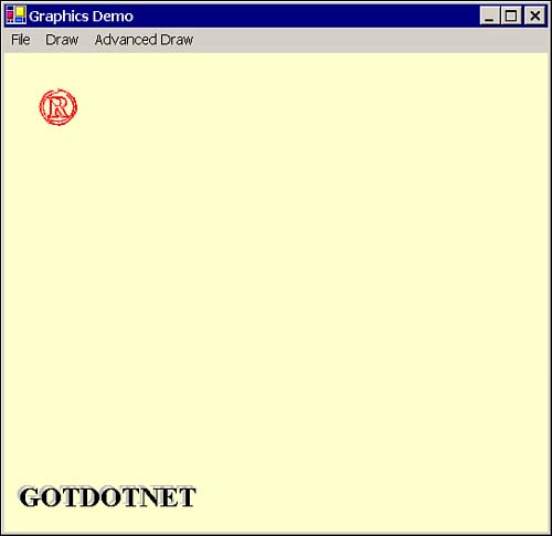
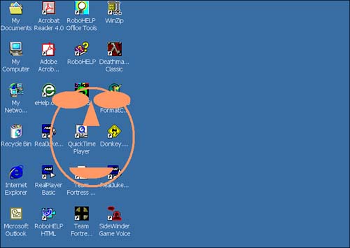
Advanced Drawing Truly advanced graphics applications are an art form. Video games like Half Life that render moving, jumping, and running images in a 3D world are excellent examples of the result of graphics programming in the hands of talented craftsmen. Whether Visual Basic .NET will be used to write multiplayer Internet games remains to be seen. At TechEd the game Donkey.Net demonstrated that advanced 3D imagery could be created in VB. (Donkey.Net> used the Revolution3D graphics engine implemented in VB6, but the game is actually implemented in VB .NET.) At the time of this writing you could still download Donkey.Net from the Microsoft Web site. This section will not teach you how to create visually complex results as demonstrated by games like Quake or Half Life, but you will learn more about GDI+ features in the System.Drawing.Drawing2D namespace that are available to help you get started. You will probably find some of these capabilities helpful in business programming, too. Drawing CurvesThe Graphics object defines a method for drawing curves based on multiple points. The DrawBezier and DrawBeziers methods take four points and an array of Points, respectively, including a starting and ending point and points in between that define the shape of the curve. The Bzier drawing capabilities allow you to draw elaborate curves as long as you can define the points that describe the curve. Note Bzier curves, or splines, were invented by Pierre Bzier for applications in the automotive industry. Bzier splines are curves based on four points and have found widespread use in CAD systems and defining the outline of fonts. For our purposes, Bzier curves are curves defined by points. Drawing Complex Curves, or Bzier CurvesInstead of contriving random curves to demonstrate the curve drawing capabilities of the Graphics class, the example in this section copies points described by a GraphicsPath and uses those points to render the image using DrawBeziers. Listing 17.6 demonstrates code that draws the curve shown in Figure 17.3. An overview follows the listing. (The GraphicsPath is covered in the next section.) Figure 17.3. A Bzier curve drawn from a GraphicsPath initialized with Chr(174). Listing 17.6 A complex array of points used to draw a moderately complex Bzier curve based on the symbol1: Private Overloads Function GetAdjustedCount(_ 2: ByVal Size As Integer) As Integer 3: 4: While ((Size - 4) Mod 3 <> 0) 5: Size -= 1 6: End While 7: 8: Return Size 9: End Function 10: 11: Private Overloads Function GetAdjustedCount(_ 12: ByVal Source() As PointF) As Integer 13: Return GetAdjustedCount(Source.GetUpperBound(0)) 14: End Function 15: 16: Private Sub CopyPoints(ByVal Source() As PointF, _ 17: ByRef Target() As PointF) 18: 19: ReDim Target(GetAdjustedCount(Source) - 1) 20: Array.Copy(Source, Target, Target.Length) 21: End Sub 22: 23: Private Function GetPath2() As Drawing2D.GraphicsPath 24: GetPath2 = New Drawing2D.GraphicsPath() 25: GetPath2.AddString(Chr(174), FontFamily.GenericSerif, _ 26: FontStyle.Bold, 100, New PointF(50, 50), _ 27: StringFormat.GenericDefault) 28: End Function 29: 30: Private Sub DrawBezier(ByVal G As Graphics) 31: Dim Points() As PointF 32: CopyPoints(GetPath2.PathPoints, Points) 33: G.DrawBeziers(Pens.Red, Points) 34: End Sub DrawBeziers draws multiple curves. If you call Graphics.DrawBezier (singular), you will need to pass four points. If you call Graphics.DrawBeziers (plural), you will need to pass four points plus an additional number of points evenly divisible by 3 or you will get a System.ArgumentException error. Note Depending on your keyboard's character set, you can get different results. If the code seems to work correctly but you get a blank screen, replace the Chr(174) with some alternate random numbers . The first overloaded GetAdjustedCount method in Listing 17.6 drops a few points to make the equation (points 4) Mod 3 = True. The second overloaded GetAdjustedCount method takes an array of points and passes the size of the array to the original method on lines 1 to 9. (Having two GetAdjustedCount methods simply makes it more convenient to ask for the correct count in the main method, DrawBezier in lines 30 to 34.) Tip If you do need a temporary variable that is the same type as a function's return type, you can use the function name instead of introducing a new temporary variable (see the function GetPath2 from Listing 17.6). CopyPoints copies the Source points into the Target points; Target points are passed ByRef because CopyPoints modifies the array on line 19. If we changed only the elements of the array, Target, we could pass the array ByVal. GetPath2 creates a GraphicsPath object and initializes it with the ASCII character 174. (We will discuss GraphicsPath in the next section.) Finally, my DrawBezier method creates an array of points, copies the points from the GraphicsPath.PathPoints, and uses the adjusted points to draw the curve in Figure 17.3. GraphicsPath ClassThe graphics engine maintains graphics as coordinates of geometric shapes in world-space. The GraphicsPath class is responsible for maintaining the coordinates describing the figures described by the GraphicsPath. Paths are used to draw outlines, fill shapes, and create clipping regions . A path can contain any number of figures, referred to as subpaths. New figures are started when you create a GraphicsPath, call CloseFigure or Graphics.FillPath, or you explicitly call StartFigure. As demonstrated in the preceding section, strings can be used to initialize graphics paths (see line 25 of Listing 17.6). Additionally, Bzier curves, simple curves, polygons, rectangles, ellipses, lines, and pies can be added to a GraphicsPath. When you've created a GraphicsPath object, you can get the points that describe the path or you can perform other operations on the image. PathPointsThe PathPoints property is a read-only property that returns an array of PointF structures. Line 32 of Listing 17.6 uses the points returned from GraphicsPath.PathPoints to draw the Bzier curve shown in Figure 17.3. PointCountThe PointCount property is a read-only property that indicates the number of points in the GraphicsPath. You can also get the number of points from the Array.GetUpperBound method from the array PathPoints. ReverseGraphicsPath.Reverse reverses the order of the points in the PathPoints array. Using reversed PathPoints to draw a Bzier curve does not result in a mirror image; rather, the points are drawn in reverse order. Listing 17.7 is excerpted from a C# example in the MSDN help files. The example reverses the path points for a line, ellipse, and arc and displays all of the path points in initial order and again after they have been reversed . Listing 17.7 Reversing the order of PathPoints1: Private Sub Reverse(ByVal G As Graphics) 2: Dim Path As New Drawing2D.GraphicsPath() 3: Path.AddLine(New Point(0, 0), New Point(100, 100)) 4: Path.AddEllipse(100, 100, 200, 250) 5: Path.AddArc(300, 250, 100, 100, 0, 90) 6: 7: DrawPoints(G, Path.PathPoints, 20) 8: Path.Reverse() 9: DrawPoints(G, Path.PathPoints, 150) 10: End Sub 11: 12: Private Sub DrawPoints(ByVal G As Graphics, _ 13: ByVal Points() As PointF, ByVal Offset As Integer) 14: 15: Dim Y As Integer = 20 16: Dim I As Integer 17: Dim AFont As New Font("Arial", 8) 18: 19: For I = 0 To Points.Length - 1 20: G.DrawString(Points(I).X.ToString & _ 21: ", " & Points(I).Y.ToString, AFont, _ 22: Brushes.Black, Offset, Y) 23: Y += 20 24: Next 25: End Sub Note The sample code was ported from a C# example in the help files. The code was translated line for line, demonstrating the very close match in capability between C# and Visual Basic .NET. Choosing Visual Basic over C#, or vice versa, is referred to as a lifestyle choice. The implication is that there are no practical technical reasons for choosing C# over VB .NET; program in the language you like. The listing adds a line, ellipse, and arc to the graphics path on lines 2 through 5. Lines 7, 8, and 9 draw the point values, reverse the order of the points, and draw the point values in their new order. Call Graphics.DrawBezier to see that the same image results before and after the point order is changed. TransformThe GraphicsPath.Transform method applies a matrix transform to the GraphicsPath and can be used to rotate, translate, skew, or scale a GraphicsPath. To transform a GraphicsPath, create an instance of a Matrix object (found in the System.Drawing.Drawing2D namespace), invoke one of the transformation methods on the Matrix, and then call GraphicsPath.Transform(Matrix). Creating a MatrixThe Matrix class has a default constructor that allows you to create an instance of the matrix without any parameters, or, you can constrain the matrix to a specific region by passing a rectangle and an array of points. The following code demonstrates default construction of a Matrix. Dim MyMatrix As New Matrix With the Matrix object, we can invoke methods to describe the impact the matrix will have on the GraphicsPath when the matrix is passed to the Transform method. ScalingUsing the object from the preceding section, MyMatrix.Scale(2, 2) scales the matrix object by the X,Y vectors where X = 2 and Y = 2. Modifying DrawBezier from Listing 17.6 to incorporate the scale transform yields the code shown in Listing 17.8. Listing 17.8 An excerpt from Listing 17.6 in which we modified DrawBezier to scale the Bzier by the vector 2, 21: Private Sub DrawBezier(ByVal G As Graphics) 2: 3: Dim Points() As PointF 4: Dim Path As Drawing2D.GraphicsPath = GetPath2() 5: Dim AMatrix As New Drawing2D.Matrix() 6: 7: AMatrix.Scale(2, 2) 8: Path.Transform(AMatrix) 9: CopyPoints(Path.PathPoints, Points) 10: G.DrawBeziers(Pens.Red, Points) 11: 12: End Sub The only modification from Listing 17.6, lines 30 through 34, is the introduction of a temporary Path to store the GraphicsPath object, allowing us to invoke the Transform method, the instantiation of the new matrix. Lines 7 and 8 scale the matrix and apply the matrix transform to the GraphicsPath object Path. The end result of this subtle change is that the registered trademark symbol () will be displayed roughly twice as large as the original shown in Figure 17.3. TranslatingMatrix.Translate( X , Y ) applies the translation vector defined by X and Y to a GraphicsPath. The net result is that the world-space position of the graphics is moved. (Replace Scale on line 7 of Listing 17.8 with Translate to demonstrate the difference between scaling and translating.) InvertingThe Matrix.Invert method will invert a Matrix transform if the matrix is invertible. You can call Matrix.IsInvertible to determine whether a particular matrix instance is invertible. Inserting AMatrix.Invert() between lines 7 and 8 of Listing 17.8 will invert the doubling in size of the matrix and halve the matrix instead, resulting in an image that is smaller than the original. RotatingRotating a matrix results in a clockwise rotation around the origin. For example, AMatrix.Rotate(10) will rotate the GraphicsPath object 10 degrees in a clockwise position around the origin. To visualize the result, draw an imaginary line from 0, 0 (the upper-left corner) of the control that will display the image. Then, draw a vector 10 degrees down from the first line and move the center of the image to a point along the new vector a radial distance equal to the distance from the origin to the image's current location. The effect is an orbital path around the origin. WarpThe GraphicsPath.Warp method applies a warp transform described by a parallelogram and a rectangle. Warp causes the effect that results from leaving vinyl LPs in the sun too long. (You remember LPs, don't you? They're the Long Playing records that predate audio cassettes and CDs.) Listing 17.9 draws a GraphicsPath object with a warped appearance. Listing 17.9 Applying a warp transform to a GraphicsPath1: Private Sub DrawBezier(ByVal G As Graphics) 2: 3: Dim Points() As PointF 4: Dim Path As Drawing2D.GraphicsPath = GetPath2() 5: Dim AMatrix As New Drawing2D.Matrix() 6: 7: Dim ARectangle = New RectangleF(0, 0, 100, 200) 8: Dim AParallelogram() As PointF = {New PointF(200, 200), _ 9: New PointF(400, 250), New PointF(220, 400)} 10: 11: Path.Warp(AParallelogram, ARectangle, AMatrix, _ 12: Drawing2D.WarpMode.Perspective, 0.5) 13: 14: CopyPoints(Path.PathPoints, Points) 15: 16: G.DrawBeziers(Pens.Red, Points) 17: 18: End Sub DrawBezier in the example is again taken from the original in Listing 17.6. In the preceding example, a parallelogram defined by the three points on lines 8 and 9 and the rectangle on line 7 are used to define the warp. (If you omit the fourth point of the parallelogram, it is implied by the first three points.) The parallelogram, rectangle, and matrix are all passed to the GraphicsPath.Warp method resulting in a warped or stretched effect. WidenThe GraphicsPath.Widen method takes a Pen or a Pen and a Matrix and adds an additional outline to the GraphicsPath. Region ClassThe Region class is a more powerful version of its cousin the Rectangle. Regions are composed of the interior part of a graphic described by paths and rectangles. Like GraphicsPath, regions are defined in world-space coordinates, making them scalable. Regions, not rectangles, are used to define the drawing area of a window and are used to perform hit-testing . By assigning a Region object to the Region property, you can define shaped forms that are described by GraphicsPath objects. (The ShapedForm.sln from Chapter 15 demonstrates using a Region to create a custom shaped form, and the next section explores the topic of shaped forms in further detail.) Shaped FormsJohn Percival demonstrates how to use the API to create shaped forms in an article "Creating Odd Shaped Forms" published on www.vbworld.com by creating a form in the shape of a smiley face. To Mr. Percival's credit, the project imports a dozen or so API methods and completes the task in an additional 50 to 100 lines of code, an example of mental gymnastics. What a good object-oriented framework does for us is introduce new things and make old things easier. By incorporating spurious API features into a coherent framework, capabilities are organized by utility and consequently easier to use. Listing 17.10 demonstrates code that creates a smiley face form (see Figure 17.4). The form is similar to the example in the vbworld.com example by John Percival. In the VB6 example, when the API functions are included, the code is all about drawing the shapes and defining the regions that describe the form. For this reason the code in the VB6 example (not provided, but available online at www.vbworld.com) is similar to the VB .NET example in Listing 17.10. The biggest difference is in the tenor of the code. Figure 17.4. A smiley face form uses clipping regions to define the boundaries of the form. Listing 17.10 A form based on simple line, curve, and polygon regions1: Public Class Form1 2: Inherits System.Windows.Forms.Form 3: 4: [Windows Form Designer generated code] 5: 6: Private Sub AddOutline(ByVal Face As Region) 7: 8: Dim OutlinePath As New Drawing2D.GraphicsPath() 9: OutlinePath.AddEllipse(5, 90, 195, 230) 10: Dim Outline As New Region(OutlinePath) 11: 12: Dim InlinePath As New Drawing2D.GraphicsPath() 13: InlinePath.AddEllipse(10, 95, 185, 220) 14: Dim Inline As New Region(InlinePath) 15: 16: Dim Ring As New Region() 17: Outline.Xor(Inline) 18: Face.Intersect(Outline) 19: 20: End Sub 21: 22: Private Sub AddEyes(ByVal Face As Region) 23: 24: Dim LeftEyePath As New Drawing2D.GraphicsPath() 25: LeftEyePath.AddEllipse(10, 100, 85, 40) 26: 27: Dim RightEyePath As New Drawing2D.GraphicsPath() 28: RightEyePath.AddEllipse(105, 100, 85, 40) 29: 30: Dim LeftEye As New Region(LeftEyePath) 31: Dim RightEye As New Region(RightEyePath) 32: Face.Union(LeftEye) 33: Face.Union(RightEye) 34: 35: End Sub 36: 37: Private Sub AddNose(ByVal Face As Region) 38: Dim Nose(2) As PointF 39: Nose(0).X = 100 40: Nose(0).Y = 120 41: Nose(1).X = 80 42: Nose(1).Y = 180 43: Nose(2).X = 120 44: Nose(2).Y = 180 45: 46: Dim NoseRegionPath As New Drawing2D.GraphicsPath() 47: NoseRegionPath.AddPolygon(Nose) 48: Dim NoseRegion As New Region(NoseRegionPath) 49: Face.Union(NoseRegion) 50: 51: End Sub 52: 53: Private Sub AddLips(ByVal Face As Region) 54: 55: Dim TopLipPath As New Drawing2D.GraphicsPath() 56: TopLipPath.AddArc(50, 250, 100, 50, 0, 180) 57: Dim TopLip As New Region(TopLipPath) 58: Face.Union(TopLip) 59: 60: End Sub 61: 62: Private Sub DrawFace() 63: Dim Face As New Region() 64: AddOutline(Face) 65: AddEyes(Face) 66: AddNose(Face) 67: AddLips(Face) 68: Region = Face 69: End Sub 70: 71: Private Sub Form1_Load(ByVal sender As System.Object, _ 72: ByVal e As System.EventArgs) Handles MyBase.Load 73: BackColor = Color.Salmon 74: DrawFace() 75: End Sub 76: 77: Private Sub MenuItem1_Click(ByVal sender As System.Object, _ 78: ByVal e As System.EventArgs) Handles MenuItem1.Click 79: Application.Exit() 80: End Sub 81: 82: End Class Note No special technique was used to contrive the regions. Percival's code was used as a starting point reference for the general appearance, and trial and error was used to create the image shown in Figure 17.4. For advanced images, a more advanced approach needs to be devised. When the main form loads, the BackColor is set to Color.Salmon and DrawFace is called. The application does more than draw the face; the form actually is the face. Thus if you click on a visible part of the face (see Figure 17.4), you are interacting with the form; otherwise , you are interacting with whatever appears behind the form. The DrawFace method adds an outline region, eyes, nose, and lips to a Region object, using variations of unions and intersections. The basic process is to create a GraphicsPath, add some points to the path, and construct a Region, adding the GraphicsPath object to the Region. For example, AddNose on lines 37 to 51 creates a GraphicsPath object and adds a polygon describing the nose and adds the polygon to the nose region. The NoseRegion is then added to the Region for the entire Face with a Union operation, Face.Union(NoseRegion). To demonstrate that the face is now the form, a ContextMenu is associated with the form's ContextMenu property. If you right-click over a filled-in area of the smiley face, the context menu is displayed. Click anywhere else and you are clicking on something unrelated to the form. Icon ClassThe Icon class is in the System.Drawing namespace. Icon makes it easier to load an icon from an external file, a stream, or use an existing icon as a template. Dim AnIcon As New Icon("my.ico") will create an instance of a new icon and load it from a file named my.ico in the current directory. Icon has properties that are self-explanatory: Width, Height, Size, and Handle. Additional useful methods include Save, which allows you to save the icon to a Stream, and ToBitmap, which converts the icon to a Bitmap object. Imaging NamespaceThe System.Drawing.Imaging namespace contains classes for managing pixel-based pages, such as JPEG and BMP files that might not be suitable for representation using vector-based graphics. The System.Drawing namespace contains classes for managing primitives, like lines, curves, and figures, as we have seen. The System.Drawing.Imaging namespace contains classes for managing images that cannot be represented using vector-based primitives, such as photographs. Listing 17.11 demonstrates how various bitmapped images can be loaded and displayed using the System.Drawing.Imaging.Bitmap class. The images demonstrated include ICO, WMF, JPG, BMP, GIF, and EMF files. Listing 17.11 Bitmapped images supported by classes in the System.Drawing.Imaging namespace1: Imports System.Drawing.Drawing2D 2: Imports System.Drawing.Imaging 3: 4: Public Class Form1 5: Inherits System.Windows.Forms.Form 6: 7: [Windows Form Designer generated code] 8: 9: Private AnImage As Bitmap 10: 11: Private Sub Form1_Paint(ByVal sender As Object, _ 12: ByVal e As System.Windows.Forms.PaintEventArgs) _ 13: Handles MyBase.Paint 14: 15: If (AnImage Is Nothing) Then Exit Sub 16: e.Graphics.DrawImage(AnImage, 10, 10) 17: 18: End Sub 19: 20: 21: Private Sub Form1_Load(ByVal sender As System.Object, _ 22: ByVal e As System.EventArgs) Handles MyBase.Load 23: 24: ComboBox1.Text = vbNullString 25: Dim Files As New IO.DirectoryInfo("..\ Images\ ") 26: Dim FileInfos() As IO.FileInfo = Files.GetFiles("*.*") 27: 28: Dim Info As IO.FileInfo 29: 30: For Each Info In FileInfos 31: ComboBox1.Items.Add(Info.FullName) 32: Next 33: End Sub 34: 35: Private Sub ComboBox1_SelectedIndexChanged(_ 36: ByVal sender As System.Object, _ 37: ByVal e As System.EventArgs) _ 38: Handles ComboBox1.SelectedIndexChanged 39: 40: Try 41: AnImage = New Bitmap(ComboBox1.Text) 42: Invalidate() 43: Catch Except As System.Exception 44: MsgBox(Except.Message) 45: End Try 46: End Sub 47: 48: Private Sub Button1_Click(ByVal sender As System.Object, _ 49: ByVal e As System.EventArgs) Handles Button1.Click 50: 51: If (AnImage Is Nothing) Then Exit Sub 52: AnImage.RotateFlip(RotateFlipType.Rotate90FlipX) 53: Invalidate() 54: End Sub 55: End Class The example is straightforward. The Load event loads all of the files in the Images subdirectory into the combo box using System.IO capabilities (lines 21 to 33). Each time the user selects an image file from the combo box, the image is updated, the form is invalidated, and the new image is painted on the form. The sample images demonstrate that the Bitmap class is capable of working with a wide variety of images; notice that there is no special code for managing any particular kind of compressed image. Further, VB .NET provides support for managing custom images via the Encoder and Decoder classes. You can use the Encoder and Decoder objects to extend GDI+ to support custom image formats. |

| | |
| Team-Fly |
| Top |