5.6 Designing VPNs
|
|
5.6 Designing VPNs
5.6.1 Design models
There are two basic design models for building IVPNs: the overlay model and the peer model. These design approaches are differentiated by how tightly coupled the VPN and service provider infrastructure are, which directly influences the level of service and management that can be offered to the user by the service provider.
Overlay model
The overlay model comprises an end-to-end VPN, which normally originates and terminates inside intranet sites and is created by CPE equipment (such as two firewalls). From the provider's perspective the VPN is client initiated, or voluntary. The service provider's backbone is effectively transparent to the VPN, and the VPN routing infrastructure is independent of the provider's routing infrastructure. The advantages of this approach are that the network operates as a single virtual network and has a single management domain. Routing policy can be enforced globally, and Layer 3 troubleshooting can be done without involving the service provider. From the service provider's perspective the VPN is simply IP traffic that it does not need to manage proactively.
The disadvantages of this approach are that all remote sites must be fully meshed to achieve any-to-any connectivity. If two sites are not directly connected, then packets must traverse the provider's backbone twice (i.e., from the source site over the backbone to some intermediate site and then back over the backbone to the target site). This increases latency, degrades efficiency, and may incur additional cost. Since the service provider must provision each virtual connection, a full-mesh topology may simply not scale for many large organizations. Another problem with this approach is that the provider has little visibility of the VPN and may not be able to offer value-added service or the level of QoS granularity required by users.
Peer model
In a peer model the VPN and the service provider network are tightly coupled. The provider's backbone infrastructure peers with the VPN network and routing is well integrated. The service provider has more work to do, proportional to the number of sites. This model enables optimal site-to-site routing to be achieved, because the provider's routing equipment has full visibility over the VPN forwarding requirements. Based on this additional information the provider network could allocate resources much more intelligently than with an overlay model. QoS can be allocated with much better granularity, since the provider network clearly understands what resources each VPN tunnel requires.
The disadvantage of the peer model is that administrative control of the network is fragmented. Layer 3 troubleshooting can be much more complicated, since both the user and provider staff need to cooperate. Since routing information is integrated, misconfigurations on CPE equipment can adversely affect backbone devices and vice versa. Illegal or private addressing schemes inside the subscriber networks must be handled consistently (possibly requiring support for overlapping IP address ranges in different VPNs). Security is also somewhat compromised, since internal addresses and routing topology information are exposed to the ISP (in the overlay model this would all be hidden).
5.6.2 Routing
Tunneling can disguise the operating characteristics of an end-to-end path, masking its true performance and possibly misleading dynamic routing protocols into making poor (and possibly unexpected) forwarding decisions. For example, distance-vector routing protocols (such as RIP) generally select paths based on hop count alone and may prefer a tunnel interface to a real interface (resulting in not-needed traffic being forwarded down the tunnel). A tunnel could traverse a number of different physical links of varying speeds, and a faster path could be available through a non-VPN interface. When configuring tunneling, take note of the media and available bandwidth of the links the tunnel traverses, as well as the metrics used by each routing protocol. Take particular care to avoid inadvertently configuring recursive routing loops (where the best path to the tunnel destination is via the tunnel interface). If a router detects a recursive routing loop, it should ideally shut down the tunnel interface for a predefined hold-down period and issue appropriate alerts or warnings to the network administrator. An indication that a loop has been detected might be that the tunnel interface is up, but the line protocol is down.
Routing loops can be avoided by using different routing protocols for VPN and normal IP network traffic (not always possible), or by setting a high metric for the tunnel interface (so that non-VPN traffic does not get routed incorrectly). You could also keep the IP address ranges for the VPN and non-VPN networks distinct (i.e., use a major address for the tunnel network that differs from the IP network). This will also assist debugging.
5.6.3 Interaction with firewalls
There are commercial firewall products that also originate and terminate VPNs. While this simplifies the configuration and deployment issues, it is unlikely in the short term that such devices will offer sufficient throughput to handle large central site applications without hardware assist. In many cases it is likely that a specialized VPN device will be used together with a packet filtering firewall or stateful firewall, possibly from different vendors. This presents us with several design, management, routing, and security issues, as illustrated in Figure 5.24. Some of these issues can be described as follows:
-
VPN fronting the firewall—In Figure 5.24(a), VPN connections will be unencrypted before presenting to the firewall. This compromises end-to-end VPN security (the VPN may also be terminated at a point considered insecure by the intended recipient). There is also no way to tell which traffic was originally encrypted or if it has been tampered with. The VPN device also requires protection from direct attacks via access lists or policy settings. However, the firewall does not need to be capable of passing IPSec traffic (e.g., proxy firewalls may not), and standard firewall policy can be applied to all VPN traffic.
-
VPN behind the firewall—If the VPN device is placed behind the firewall (Figure 5.24[b]), then the firewall cannot access the content and cannot verify whether viruses or illegal activities are being tunneled within the VPN connection. In effect, you need to punch a hole through the firewall to allow VPN traffic through. However, this lends the internal network vulnerable to a possible denial-of-service attack. The firewall needs to be capable of passing IPSec traffic unmodified; conversely, the VPN box has to pass unencrypted (non-VPN) traffic with sufficient throughput. Some VPN boxes do not support filters or access lists. On the plus side this means that the VPN device is also protected by the firewall, and the firewall is not burdened by processing VPN traffic.
-
VPN parallel with the firewall—This generally works well for all incoming VPN and non-VPN traffic since each device handles only what is relevant (Figure 5.24[c]). However, the problem lies with routing outbound traffic. Clients typically have only one default gateway set, and this may result in VPN traffic being forwarded to a router or firewall rather than the VPN device, leaving the network unencrypted. If the destination addresses are known in advance (say with a stable site-to-site VPN, or known client VPNs), then it should be possible to configure the router to reflect such traffic back toward the local VPN device using access control lists or policy settings. Again, the VPN device requires protection from direct attacks via access lists or policy settings. Traffic leakage should also be avoided with the VPN box set to drop all non-VPN traffic.
-
VPN on a stick behind the firewall—This is generally applicable only to trusted environments, since again a hole must be punched through the firewall to allow VPN traffic in (Figure 5.24[d]). The VPN device is placed in line with the firewall and clients so that encrypted and unencrypted VPN traffic traverses the same physical network. This solution does not scale well, and there may be routing issues with default gateway—directed traffic.
-
VPN on a stick fronting the firewall—This is only really applicable where the firewall cannot cope with unfiltered traffic, as well as for small networks (Figure 5.24[e]). Again, the VPN device requires protection from direct attacks via access lists or policy settings.
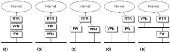
Figure 5.24: Alternative locations for VPN termination in cooperation with a firewall and router.
In practice the VPN system is often placed behind the firewall, as illustrated in Figure 5.25. This offers most of the benefits with minimal complexity. Policy or filtering on both the firewall and router need to accept authorized tunnels to pass through.
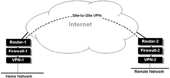
Figure 5.25: VPN termination between two trusted sites. The firewall and router must be configured to accept any VPN tunneling or key-management protocols.
5.6.4 Performance
Tunneling is CPU intensive, and encryption is even more so. Expect significant degradation in throughput over normal IP packet forwarding if tunneling is enabled with encryption. Software-based encryption schemes are suitable only for small numbers of site-to-site tunnels. If you intend to terminate large numbers of encrypted tunnels (e.g., thousands or tens of thousands at a central site), you really need to select specialized hardware that can perform encryption with hardware assist. It is also highly desirable to select products that offer some form of clustering or HA capability to promote scalability.
Fragmentation
Any protocol that adds overhead is more likely to introduce IP fragmentation issues, since large IP packets may exceed their MTU. Fragmentation is generally to be avoided, since it degrades VPN performance (more packets must be processed, and fragments must be buffered and reassembled in order to perform tasks such as authentication). If the application servers are within your domain, you may be able to reduce their MTU to allow for additional VPN headers.
Another issue with IP fragmentation is the DF (Don't Fragment) bit. Note that IPSec always copies the DF bit setting from the inner to the outer IP header in tunnel mode. This may be overridden, since it may cause problems for some TCP stacks and firewalls (changing this setting should be avoided if at all possible as it may result in suboptimal fragmentation).
5.6.5 Scalability and management
One of the clear indications at present is that new solutions providing real VPN scalability are going to be required. The next-generation IP VPN will require the ability to provision thousands of sites per VPN and thousands of VPNs. This requires simplified management to allow VPN membership and large-scale deployment. Users are demanding any-to-any connectivity for extended intranets and extranets, which requires VPNs to encompass multiple businesses. Support for sophisticated IP intranet applications, such as dynamic bandwidth allocation, application-specific transport characteristics (e.g., voice), and new services and service classes are required. Multicast technologies for multimedia applications and multiple service classes to support mission-critical and time-sensitive traffic such as video and voice will be key to growth.
Meeting these requirements requires a new paradigm for building these highly scalable and capable IP VPNs. This service differs from previous models, because the network is directly aware of the VPNs. As stated earlier, today's VPNs are generally transparent to the network infrastructure, limiting scalability and flexibility.
MPLS-based VPN backbones
MultiProtocol Label Switching (MPLS) is viewed by many as the most appropriate delivery mechanism for providing scalable VPNs over backbone networks (by backbone we mean core-wide area networks, not local backbones). MPLS in essence provides switched and virtual circuit capabilities, called Label-Switched Paths (LSPs) over an IP core. MPLS enables individual or groups of VPNs with similar routing and QoS requirements to be mapped onto LSPs. Clearly, many VPN applications are end to end, and MPLS is not an end-to-end technology since its resource demands are significant. This will require MPLS LSPs to be mapped onto LAN-based VPNs at the edge.
|
|