4.1 Multicast application and routing concepts
|
|
4.1 Multicast application and routing concepts
Before launching into detail about various protocols of importance in multicasting, we need to review some of the key application and technology issues.
4.1.1 Multicast groups
A fundamental part of multicast support is the concept of a multicast group. A multicast group is a logical association of senders and receivers, usually related by application. Groups are usually formed dynamically; receivers request to join or leave a group at will, although statically configured membership is also possible. If there is only one sender, the group is called a point-to-multipoint group. If there are multiple senders, the group is called a multipoint-to-multipoint group. In the IP world a multicast group is associated with a specific class D IPv4 address—for example, 224.0.0.5 is the multicast group used by OSPF routers on which to send hello messages on multiaccess networks. Some of the more important (for this chapter) well-known addresses designated by IANA include the following:
-
224.0.0.1—all systems on the subnet
-
224.0.0.2—all routers on the subnet
-
224.0.0.4—all DVMRP routers
-
224.0.0.5—all OSPF routers
-
224.0.0.6—all OSPF designated routers
-
224.0.0.9—RIP2 routers
-
224.0.0.10—IGRP routers
-
224.0.0.11—mobile agents
-
224.0.0.13—all PIM routers
-
224.0.0.15—all CBT routers
-
224.0.0.18—VRRP
-
224.0.0.22—IGMP
Transient addresses, which may be assigned and reclaimed dynamically, include the following:
-
224.0.1.0 to 238.255.255.255—global scope
-
239.0.0.0 to 239.255.255.255—limited scope
-
239.255.0.0/16—site local scope
-
239.192.0.0/16—organization local scope
For up-to-date assignments, see [2].
4.1.2 Mapping multicasts onto MAC addresses
We learned in Chapter 2 that IPv4 multicasts use the class D address format (with 1110 as the high-order bits and the remaining 28 bits made available for the group address). Reference [3] discusses how IP multicast addresses get mapped onto MAC addresses prior to forwarding on the wire. To recap:
-
For Ethernet and FDDI the mapping is straightforward for IPv4; the lower 23 bits of the IP address map onto the lower 23 bits of the MAC address, and the multicast bit is set. For example, 224.0.0.5 translates to 0x01005e000005. With IPv6 a 128-bit multicast address comprises an 8-bit prefix of all ones, a 4-bit flags field, a 4-bit scope field, and a 112-bit identifier. The flags field indicates whether this address is permanently assigned or not. The scope field indicates the application of the address (from a single subnet to global).
-
For Token Ring an IP multicast address maps onto a single Token Ring functional address or the all, ones broadcast address. For example, 224.0.0.0 maps to c0-00-00-04-00-c0-00-00-04-00-00 (using the noncanonical format) or ff-ff-ff-ff-ff-ff. This is typically configurable on the interface.
4.1.3 Multicast application models
It is important to understand from the outset that multicasting is inappropriate for most traditional applications. The types of application best suited for multicast distribution are generally characterized by a high degree of asymmetry, the need to send the same information to many receivers simultaneously, and typically (though not always) some real-time constraint. Applications in this class include live market data feeds, videoconferencing, audioconferencing, push applications, streaming media, interactive whiteboards, database replication, corporate communications, data warehousing, distributed computation, real-time workgroups, and interactive distance learning. This does not preclude other specialized application types from the benefits of multicasting—for example, applications that synchronize information among multiple nodes or attempt to discover services are likely to benefit from multicasting (in fact the latest generation of routing protocols such as OSPF have made good use of multicasting for some time). For applications suitable for multicasting there are essentially two data distribution models of interest, as follows:
-
One-to-many—With this model the application transmits the same information to many receivers simultaneously, so the data flow is one way—for example, applications that transmit real-time stock quotes or news updates.
-
Many-to-many—With this model the application shares information between a number of machines simultaneously, so the data flow is bidirectional. Since every receiver is potentially a transmitter, this form of application is in one-to-many mode when sending and many-to-one mode when receiving.
To date, most networked applications have relied almost exclusively on unicast or broadcast delivery mechanisms, with multicasting limited to specialized applications such as routing or control protocols. For certain types of user applications (e.g., market data feeds, multiuser videoconferences, and interactive distance learning) this is a particularly inefficient way to distribute information. These applications have a significant feature in common: large amounts of identical data being sent to many receivers simultaneously. Unicast and broadcast models can be described as follows:
-
Reliable unicast model—With a unicast approach this requires discrete sessions to be established from the source to each recipient, and the source must send identical information down each connection. As the number of recipients increases, this approach begins to impose enormous overheads on both the sender and the network, and it cannot scale. The unicast model is reliable because the application makes use of the error detection and correction facilities of reliable transport protocols such as TCP.
-
Unreliable broadcast model—The broadcast flooding approach is easier to implement; however, with a broadcast distribution strategy traffic is almost impossible to contain on flat networks. Special relay support is relied on to move traffic across routers. The broadcast model is unreliable because the application makes use of the best-effort facilities of datagram-based transport protocols such as UDP. Broadcasts affect all nodes on a multiaccess network, whether they are interested in the packet or otherwise; it is notable that broadcasts have been outlawed in IPv6.
Both unicast and broadcast mechanisms place increasing load on device CPUs and the network as the number of group members increases. Unicast distribution also requires the server to maintain session states for each individual receiver. Neither of these approaches can scale. In contrast, multicasts are handled differently by the receiver's NIC; a receiving station can be a member of one or more multicast groups, and the NIC can discard any frames not destined for those groups (typically using a high-speed hash function) without interrupting the CPU. Another advantage from the network designer's perspective is that multicasts can be filtered if required, since they can be differentiated from background broadcast traffic. This might be appropriate for additional traffic management purposes or for security (security policies could be applied on devices such as firewalls).
4.1.4 Multicast application design guidelines
Reference [4] describes the host requirements for supporting IP multicast and the default behavioral characteristics of multicast applications, as follows:
-
An application must explicitly join a multicast group to receive datagrams destined for that group but need not be a member of a multicast group to send datagrams to it.
-
When an application joins a group, it joins on only one local interface.
-
When an application sends to a multicast address, outgoing datagrams are sent from only one local interface and have a default TTL of 1.
-
All datagrams sent are also, by default, received on the same interface (i.e., datagrams are effectively looped back).
Reference [4] recommends a number of API functions for configuring multicast support. These include the ability to join or leave a multicast group, set the Time to Live (TTL), define local interfaces for multicast transmission or reception, and disable loopback of outgoing multicast datagrams. All of the APIs discussed in the following section support these functions as a minimum.
IP multicast APIs
Most of the major TCP/IP host implementations now offer multicast support, either integrated directly into the OS or via system patches. These implementations also typically support IGMP [4]. The three best-known APIs for UNIX, Windows, and Apple MAC operating systems are as follows (as one would expect, these APIs offer broadly the same functionality).
-
Berkeley Sockets Multicast API—The Berkeley Sockets Multicast API is an extension to the Berkeley Socket API for UNIX platforms. While it is the de facto API for IP protocols, Berkeley Sockets is not limited to the IP family. Note that on UNIX systems you must have the relevant kernel patches installed.
-
WinSock API—Windows Sockets version 2 (from Microsoft) is designed for 32-bit Windows platforms and is not restricted to IP WinSock 2 is a subset of Berkeley Sockets (some functions such as ioctls are not supported) but adds Windows-specific functions (such as overlapping IO). WinSock 2 supports the Berkeley Sockets—compatible TCP/IP functions and also defines a set of protocol-independent multipoint APIs that can support IP multicast.
-
Open Transport API—The Open Transport (OT) API is defined by Apple Computer, Inc. as its standard interface for creating network applications on Macintosh computers. OT is a superset of the XTI standard networking API defined by the X/Open UNIX vendor consortium (XTI is itself a superset of TLI, another de facto network API). As with Berkeley Sockets and WinSock, OT is protocol independent but also includes some protocol-specific APIs for support of IP multicast.
To meet the requirements set out in [4], basic support for multicasting involves the addition of five new socket options. The Berkeley Socket Multicast API specifies two sets of functions with the prefix IP_ or IPV6_ for IPv4 and IPv6, respectively, as follows:
-
ADD_MEMBERSHIP—To join a multicast group
-
DROP_MEMBERSHIP—To leave a multicast group
-
MULTICAST_IF—To specify the default interface for outgoing multicasts
-
MULTICAST_TTL (MULTICAST_HOPS in IPv6)—To specify the scope of outgoing multicasts
-
MULTICAST_LOOP—To enable or disable loopback for outgoing multicasts
For further information on these APIs, the interested reader should refer to references [4–11].
Enabling legacy unicast applications for IP multicast
Converting an existing application to use a multicast distribution model can be relatively straightforward. The key issue is whether the application relies on a connection-oriented transport protocol (e.g., TCP) or a datagram-based transport protocol (e.g., UDP). These protocols can be described as follows:
-
Unicast datagram-based applications—Datagram-based applications are easier to adapt, since they already assume a message-oriented, unreliable Transport Layer and most likely already have reliability functions built into the application itself. Typically this simply requires remapping a small number of unicast API calls to equivalent multicast-specific API functions. Multicast sources are further required to send traffic to an IP class D destination address and to adjust the IP Time to Live (TTL) according to the desired scope (i.e., according to the number of hops anticipated in the transmission path). They may also be required to disable loopback. In order to receive data from a multicast address the application must bind to a specific port number and join the multicast group.
-
Unicast connection-oriented applications—Enabling applications that currently use connection-oriented protocols for multicast support is likely to be difficult, requiring significant redesign. These applications inherently rely on protocols such as TCP to provide reliable, acknowledged data delivery, and IP multicast is inherently unreliable (being based on UDP). Although some commercial products are shipping, standard protocols for reliable multicast are still an area of active research. Reliable IP multicast is discussed in section 4.9.
Design and implementation issues
While multicast applications can be very efficient in bandwidth utilization, they can get out of hand without some constraint in their implementation and delivery mechanisms. In particular, developers of multicast applications should aim for the following goals:
-
Constrain the scope of multicast packets—Set the IP datagram TTL value judiciously to ensure that multicast are dropped quickly once they exceed the anticipated radius of the application (generally the TTL equals the number of router hops). Of course, on Internet applications this may not be so easy, and different multicast groups may have different radii at different times, but setting the TTL to 255 is never a good choice. If possible, attempt to dynamically discover the maximum radius of the network as part of the application; if not possible, then make sure this can be tuned through the application to suit different conditions. Multicast routers may implement configurable thresholds beyond which they can drop datagrams before the maximum IP TTL value (255) is reached. Ultimately, these applications will probably use administrative scoping with special multicast addresses rather than a simple TTL.
-
Constrain and optimize bandwidth use—As part of the application development process you should characterize how much bandwidth your application requires, under a variety of conditions, and establish how its use of resources scales. If possible dynamically discover what bandwidth is available between senders and receivers and have receivers specify what service characteristic they can support.
-
Select address and port numbers carefully—As with any traffic flow over a network, it is important to be able to differentiate that flow, for traffic engineering purposes and security, or to identify the application or group of users in question (from the receiver's standpoint). With multicast application a session can be identified (denoted by a session identifier) using a combination of destination multicast address, source unicast address, transmit and receive port numbers, and protocol. Session identifiers are an important consideration in the design and execution of a multicast application, especially on a public network such as the Internet or MBone. Depending upon the level of granularity applied, multiple application flows could potentially use the same session identifiers and effectively collide. Application developers should take particular care in the choice of multicast address and port number. In some cases the only solution will be to schedule application use, to avoid application collisions.
-
Scheduling application use—If you are running several multicast applications, then (if possible) schedule major events (such as a conference or video broadcasts) so that they do not contend for bandwidth. If using the same address and port ranges, this is clearly even more important to avoid service problems.
In a small number of cases, the assignment of one or more permanent IP multicast addresses is warranted for multicast service. For example, standardized (well-known) applications and content providers with constant media streams may justify permanent multicast addresses. Permanent address and port number allocation falls under the control of the IANA [2]. In most cases addresses must be allocated from the available pool of free addresses, and on a large public internetwork there is no foolproof way for an application to select unique addressing parameters, since, by their very nature, multicast service and membership are dynamic. Strategies such as listening on an address for traffic or querying IGMP devices for membership information are, therefore, likely to fail. What is required is a coordinated approach based on a single or shared directory. Note that the MBone makes use of an application called Session Directory (SD), described in section 4.7.2, which resolves the problems of application conflicts.
4.1.5 Deployment issues on local and wide area networks
Local area deployment issues
On a multiaccess LAN, multicasting is relatively easy to implement, since IEEE 802 and other LAN protocols already provide for multicasting at the MAC layer. However, one of the main problems with real network topologies is multicast leakage—specifically, how to stop multicasts from flooding the wire once the multicast frame gets beyond a Layer 3 device. For example, many LANs employ multiport repeaters or multiport switches to collapse parts of the local area backbone for device concentration. If multicast routers are interconnected via such devices, then these concentrators will, by default, inject multicasts into all interfaces (other than the receive interface), whether there are group members attached or otherwise (see Figure 4.1). In this figure, Switch-1 receives incoming multicast packets, which it forwards (as expected) to all interfaces other than the receiving interface. Unfortunately, in this case only two users are interested in receiving these multicasts (situated on Net-1 and Net-3). The server farm and the bridged LAN (Net-4) are also affected unnecessarily. This problem exists regardless of whether or not VLANs are deployed [3]).
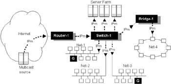
Figure 4.1: Multicast leaking in a flattened LAN environment.
Without careful monitoring you might inadvertently be flooding multicasts and wasting valuable bandwidth on parts of the network that should never see this traffic. There are several ways to resolve such problems, including the following:
-
Design around the problem—If possible, use private LAN links to interconnect the multicast-enabled interfaces on multicast routers (routers are generally configured on a per-interface basis for multicast support).
-
Use filtering on intelligent Layer 2 switches—Dumb multiport repeaters will retransmit multicast traffic to all interfaces, and there is very little you can do about it without replacing the device. Buffered Layer 2 switches can usually be configured to block specific multicasts on a per interface basis. While this could become a serious maintenance problem, it will alleviate the problem to some extent. Of course, regardless of whether group members join or leave a group, an interface enabled for multicasting may still be forwarding unwanted multicasts if other active group members exist elsewhere on the switched LAN.
-
Deploy multicast-aware switches—Perhaps the most appropriate approach is to use switches that are multicast aware, though this is likely to prove more expensive and require some strategic redesign. In this case there are several options, as follows:
-
GMRP—Use of the relatively recent IEEE 802.1 protocol called the GARP Multicast Registration Protocol (GMRP). This approach requires the host and switch to be GMRP aware and requires a change in the frame MTU size to accommodate additional data.
-
IGMP snooping—Internet Group Membership Protocol (described in section 4.2) can be deployed to operate promiscuously on Layer 2 switches (usually implemented in hardware). The switch can, therefore, examine all packets for join or leave events and reprogram interfaces accordingly.
-
Proprietary protocols—Such as the Cisco Group Membership Protocol (CGMP). In contrast to GMRP, CGMP offers a transparent approach to solving the problem through dynamic changes on the switches in response to join or leave events.
-
It is fair to say that network designers often overlook the deployment of IP multicast applications when the initial design is proposed, which in many cases is understandable. Furthermore, if you have flattened your original network with switches in key areas to take advantage of performance benefits, then this can lead to some nasty surprises when IP multicasting is subsequently enabled. Unfortunately, shared hubs and switches that don't constrain multicast flooding will need to be replaced.
Wide area deployment issues
On wide area networks, and especially on NonBroadcast MultiAccess (NBMA) networks, multicasting can be much more difficult to implement, because the wide area is often characterized by point-to-point links and circuits, as illustrated in Figure 4.2. A new approach to information distribution is required, and this has led to a new generation of multicast protocols specifically geared toward efficient information delivery across wide area internetworks. As we can see in Figure 4.2, the network comprises a number of point-to-point links and a wide area mesh network between routers. Each router attaches one or more LANs. There are several problems to resolve to provide efficient multicast delivery. How does the server know which LANs are used to attach group (G) members? How do group members register for service? What topology should be used to avoid replication? These are just some of the problems that multicast routing protocols have to resolve.
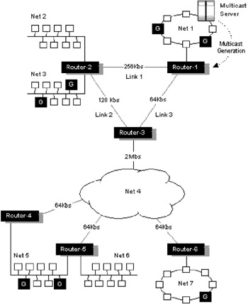
Figure 4.2: Example internetwork topology required to support multicasting.
For maximum efficiency we ideally want to send a multicast packet exactly once on each link. The topology formed is a shortest path tree, with the sender at its source. We refer to this as a multicast tree, illustrated in Figure 4.3. As indicated earlier, for a network supporting different multicast groups there are likely to be many logical Spanning Tree distribution topologies at any particular time. In Figure 4.3, note that several networks have been pruned from the tree, since they do not currently have group members. Note also that Net 5 has two possible router interfaces and so R4 has been pruned back automatically, with R5 elected as the designated forwarder (avoiding packet replication on Net 5).
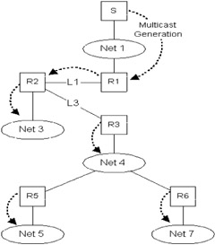
Figure 4.3: Multicast Spanning Tree, rooted at S, for the example network shown in Figure 4.2.
Given that these topologies can vary over time as group membership shifts, one can imagine that there are some interesting problems to resolve. Several of these problems are summarized as follows, and this chapter attempts to resolve these and other related questions via a number of protocols and algorithms.
-
How does a receiver learn which multicast groups are available?
-
How does a receiver register an interest in a group?
-
How does a sender discover the set of receivers in a group?
-
How does a sender ensure efficient and reliable delivery to all members of the group?
-
How does an individual recipient notify the source about problems with delivery?
-
How do senders deal with differing network delivery characteristics?
-
How does our multicast network scale?
With IP multicasting it is important to recognize that the sender and receiver are decoupled, treated as two separate entities within a multicast group, for a reason. The sender need not know the physical location or address of a receiver; it uses the multicast address as a Rendezvous Point (RP) so that the two parties can communicate. Receivers must join the RP-rooted tree, and senders must register their existence with the RP. In this way the sender is insulated from the recipients, relying upon the network to take care of multicast distribution. Note that the term rendezvous point used in this context is purely an abstraction; some routing protocols implement a physical entity (typically software running on a router) called the rendezvous point to act as an intermediary between senders and recipients.
4.1.6 Common multicast techniques
Multicasting in a wide area network introduces some particular complexities. There are potentially a large number of receivers and many sources. Sources and receivers may join or leave groups even while multicast distribution is in progress. This requires that the multicast trees must be dynamically updated to reflect current status. In multiaccess LANs (such as Ethernet or FDDI) another problem is introduced. If we have multiple access points to these LANs, say via multiple routers (as illustrated in the case of Network-5 in Figure 4.2), then we could end up forwarding duplicate multicasts to each LAN. We need to exploit the broadcast nature of such networks and ensure that only one multicast is forwarded.
If a multicast is to be forwarded to receivers over multiple router hops, then we could simply flood all multicasts throughout the network to ensure that all receivers get the data. For a single application with a well-distributed set of receivers this would work, but for a network supporting several multicast applications and a diverse population of receivers this cannot scale and is potentially highly inefficient (many segments will be receiving unwanted multicasts, which simply wastes bandwidth). Flooding runs the risk of excessive packet replication. We could avoid this by maintaining state information at each router indicating which multicasts have already been forwarded, but this is not very attractive. A better mechanism is, therefore, required for receivers to inform individual routers as to which multicasts they are interested in receiving and how to avoid duplicates.
Reverse Path Forwarding (RPF)
One simple technique for flooding multicasts intelligently is referred to as reverse path forwarding (sometimes called reverse path multicasting). With this technique a router will forward a packet from a source, S, to all its interfaces, if, and only if, the packet arrives on an interface that corresponds to the router's shortest path tree to S. An interface that passes this check is called the RPF interface. An RPF lookup for a source returns the RPF interface and the next-hop information. Packets that are received on interfaces that are not in the Spanning Tree for a particular multicast tree are simply discarded.
Reverse path forwarding allows a data stream to reach all LANs but does not prevent duplicates from occurring entirely, since we use no intelligence on the downstream flooding mechanism. We can extend the technique further by making use of the unicast routing table to control which interfaces to downstream routers are used to flood. If the downstream router, R, is not included in the shortest path tree, then it should not receive multicasts from S. This introduces another potential problem, where multiple equal-cost paths are introduced, but this can be resolved using tie breakers and heuristics, as described later in this chapter. Reverse path forwarding, and its extensions, requires each router to know its shortest path to every source and the shortest path from each neighbor to every source. This information can be recovered from the unicast routing table maintained by IGPs such as RIP, OSPF, and BGP.
Pruning and grafting
Reverse path forwarding ensures that all LANs receive multicasts, but clearly some LANs may not require them. A router attached to a LAN that does not want to receive a particular multicast group can send a prune message to its parent up the shortest path distribution tree, in order to prevent further packets from being transmitted. For example, in Figure 4.3, if group members on Network 7 decide to leave the group or are switched off, then Router-6 can send a prune request up to Router-3. Router-3 will no longer forward multicasts over Network 4 to Router-6 (it must still forward multicasts to Router-5 of course). Prune messages can be associated with a multicast group or with a particular multicast group and a multicast source (in the case where there are multiple senders you could, therefore, decide which sender to register with). In the simple case a router only needs to maintain prune indications on an output interface basis for a whole group. In the latter case a router needs to maintain information on each interface indicating both the group and sender address associations.
The mechanism for adding new branches to the multicast tree is called grafting. If a router receives requests for multicasts (from devices attached to an interface not in the current tree), it can request addition to a multicast tree by sending a graft request to its parent. In our example network (Figure 4.3), if a host on Network 6 decides to rejoin the multicast group, then Router-6 must send a graft request up to Router-3. Note that only one Round-Trip Time (RTT) from the new receiver to the nearest active branch of the tree is required for the new receiver to start receiving traffic.
Expanding ring search
Expanding ring search is a clever technique used to discover resources dynamically. It is used to discover the nearest available resources (e.g., IGMP hosts use this technique to discover the nearest multicast server). The technique exploits the Time to Live (TTL) field of IP, exploiting the following information:
-
A multicast datagram with a TTL of zero is restricted to a host (i.e., it is internal and should not be transmitted).
-
A multicast datagram with a TTL of one is restricted to a subnet (i.e., a router should not forward it).
-
A multicast datagram with a TTL greater than one is typically forwarded by routers over several hops, decremented by one at each hop, and eventually discarded when the TTL reaches zero.
By starting with a TTL of one, and then incrementing the TTL by one at each pass, a sender can perform an expanding ring search for a resource until the nearest listening resource responds. On receiving a response the sender locates the closest resource (in hops). For example, a host can use this technique to locate the nearest available server, printer, or gateway.
4.1.7 Multicast routing protocols
It is important to understand that multicast routing is quite different from unicast routing; the differences are subtle but fundamental. Whereas unicast routing is concerned primarily with the destination of a packet, multicast routing is largely concerned with its source. In a sense multicast routing is backward oriented. IP multicast traffic for a particular source-destination group pair (s, g) is transmitted from the source to multiple receivers via a Spanning Tree, which connects all the hosts in that particular group. This implies that in a large internetwork there could be many overlaid Spanning Trees, one for each group, with each topology dependent upon the location and distribution of multicast sources and recipients. Some protocols also support the concept of shared trees (*, g), where several multicast groups share a common tree. Another subtle difference is that multicast routing is generally much more dynamic compared with unicast routing. Multicast routes and multicast traffic flows depend upon the state of a multicast source and whether nodes wish to receive multicasts at any particular time. Multicast routes may, therefore, appear and disappear as part of normal operations.
There are currently a number of multicast routing protocols available for IP, and each uses different techniques to construct its multicast delivery trees. These protocols generally follow one of two basic approaches, depending on the anticipated distribution of multicast group members throughout the network. They can be described as followed:
-
Dense distribution model—This model assumes that the multicast group members are densely distributed throughout the network (i.e., many of the subnets contain at least one group member) and that bandwidth is plentiful. Dense-mode multicast routing protocols rely on a technique called flooding to propagate information to all other routers, leaving the responsibility of sensibly pruning back the various multicast trees in the hands of cooperating multicast routers. This operation is sometimes referred to as flood and prune. Dense-mode routing protocols include Distance-Vector Multicast Routing Protocol (DVMRP) and Protocol-Independent Multicast-Dense Mode (PIM-DM).
-
Sparse distribution model—This model assumes that the multicast group members are sparsely distributed throughout the network and bandwidth is possibly restricted (e.g., across many regions of the Internet or if users are connected via ISDN lines). Note that sparse-mode routing does not imply that the group has a few members, just that they are widely dispersed. In this case, flooding would unnecessarily waste network bandwidth and could cause serious performance problems. Hence, sparse-mode multicast routing protocols must rely on more efficient techniques to set up and maintain multicast trees, specifically the deployment of intermediate registration agents called Rendezvous Points (RPs) and the use of explicit joins to register interest in a group. The RP initially creates a shared tree (*, g) to enable all multicast groups to deliver traffic via the RP. Sparse-mode routing protocols include Multicast Open Shortest Path First (MOSPF), Core-Based Trees (CBT), and Protocol-Independent Multicast-Sparse Mode (PIM-SM).
Sparse-mode protocols have a number of significant advantages over dense-mode protocols. First, sparse mode offers better scalability, since only routers on the path between a source and a group member must maintain state information. By contrast, dense mode requires state information to be maintained in all routers in the network. Secondly, sparse-mode protocols are much more conservative in their use of network bandwidth, since receivers must explicitly join a group to initiate multicast traffic flow to their particular location. The disadvantages of sparse-mode protocols largely relate to the use of an RP. For example, the RP could prove a single point of failure, either through actual device failure or system overloading (although it is typically possible to deploy RPs in a load-sharing mode). The RP can also become a magnet for multicast traffic leading to nonoptimal paths. Protocols such as PIM—SM solve this problem by switching from a shared tree (*, g) to an optimal shortest path tree for the particular (s, g) multicast pair, once a specified traffic threshold is reached.
All of these multicast routing algorithms and protocols have evolved rapidly over the last few years, and currently there is no absolute winner. This chapter compares and discusses the pertinent features and deployment issues so that useful design choices can be made. We will also investigate strategies for interoperability and discuss some of the new protocols available to support real-time multicast applications.
|
|