| An nPar is a Node Partition, sometimes referred to as a Hard Partition. An nPar can be considered as a complete hardware and software solution that we would normally consider as an HP server . When we think about the basic hardware components in an HP server, we commonly think about the following: In exactly the same way as a traditional server, an nPar is made of the same basic components. A major difference between a Node Partition and a traditional server is that a traditional server is a self-contained physical entity with all major hardware components (CPU, memory, and IO interfaces) contained within a single cabinet/chassis. A node partition is a collection of components that may form a subset of the total number of components available in a single hardware chassis or cabinet. This subset of components is referred to as a node partition while the entire chassis/cabinet is referred to as a server complex . HP's implementation of Node Partitions relies on a hardware architecture that is based on two central hardware components known as: -
A cell board, which contains a CPU and RAM -
An IO cardcage, which contains PCI interface cards A cell board plus an IO cardcage form most of the basic components of how we define an nPar. Figure 2-1. Basic nPar configuration. 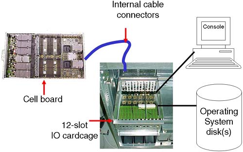
Some partitionable servers have internal storage devices, i.e., disks, tape, CD/DVD. A Superdome complex has no internal storage devices. In order for the complex to function even as a single server, it is necessary to configure at least one node partition . Without a Complex Profile, the complex has no concept of which components should be working together . The list of current Node Partitionable servers (see http://www.hp.com ”Servers for more details) is extensive and will continue to grow. While the details of configuring each individual server may be slightly different, the concepts are the same. It is inconceivable to cover every configuration permutation for every server in this chapter. In order to communicate the ideas and theory behind configuring nPars, I use a PA-RISC Superdome (SD32000) complex during the examples in this chapter. An important concept with Node Partitionable servers is to understand the relationship between the major underlying hardware components, i.e., which cells are connected to which IO cardcages. For some people, this can seem like overcomplicating the issue of configuring nPars. Without this basic understanding, we may produce a less-than - optimal partition configuration. An important concept to remember when configuring nPars (in a similar way when we configure any other server) is that we are aiming to provide a configuration that achieves two primary goals : | Basic Goals of a Partition Configuration High Performance High Availability |
Without an understanding of how the major hardware components interrelate, as well as any Single Points of Failure in a server complex, our configuration decisions may compromise these two primary goals. The primary components of a server complex are the cell board and the IO cardcage . These are the hardware components we need to consider first. 2.1.1 A cell board A cell board (normally referred to as simply a cell ) is a hardware component that houses up to four CPU modules. (Integrity servers support dual-core processors. Even though these dual-core processors double the effective number of processors in the complex, there are physically four CPU slots per cell. In each CPU slot a single, dual- core processors can be installed.) It also houses a maximum of 32 DIMM slots (on some Superdome solutions, this equates to 32GB of RAM per cell). Depending on the server we have, determines how many cell boards we have. The cell boards are large and heavy and should be handled only by an HP qualified Customer Engineer. The cells slot into the front of the main cabinet and connect to the main system backplane . A cell board can optionally be connected (via the backplane ) to an IO cardcage (sometimes referred to as an IO chassis ). On a Superdome server, this is a 12-slot PCI cardcage; in other words, the IO chassis can accommodate up to 12 PCI cards. On other servers, this is usually an 8-slot PCI cardcage . If a cell is connected to an IO cardcage, there is a one-to-one relationship between that cell board and the associated IO cardcage . The cell cannot be connected to another IO cardcage at the same time, and similarly the IO cardcage cannot be connected or shared with another cell. | The fact that the connection between a cell and an IO cardcage is OPTIONAL is a VERY important concept. The fact that a cell can be connected to a maximum of one IO cardcage is also VERY important. |
Some customers I have worked with have stipulated minimal CPU/RAM requirements and extensive IO capabilities. If you need more than 12 PCI slots (on a Superdome), you need to configure an nPar with at least two cells , each cell connected to its own IO cardcage; in other words, you cannot daisy-chain multiple IO cardcages off one cell board. This may have an impact on our overall partition configuration. The interface between cell components is managed by an ASIC (Application Specific Integrated Circuit) housed within the cell and is called the Cell Controller chip (see Figure 2-2). Communication to the IO subsystem is made from the Cell Controller, through the system backplane to an IO cardcage via thick blue cables knows as RIO/REO/Grande cables to an ASIC on the IO cardcage known as the System Bus Adapter (SBA). You can see these blue cables in Figure 2-4 and Figure 2-5. Performing a close physical inspection of a server complex is not recommended because it involves removing blanking plates, side panels, and other hardware components. Even performing a physical inspection will not reveal which cells are connected to which IO cardcages. We need to utilize administrative commands from the Guardian Service Processor (GSP) to establish how the complex has been cabled; we discuss this in more detail later. Figure 2-2. A Superdome cell board. 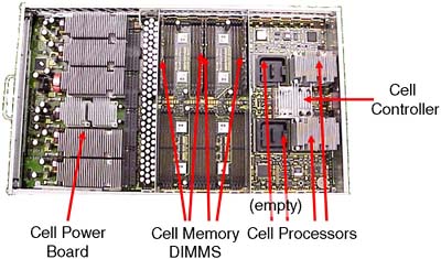
Figure 2-4. Superdome backplane. 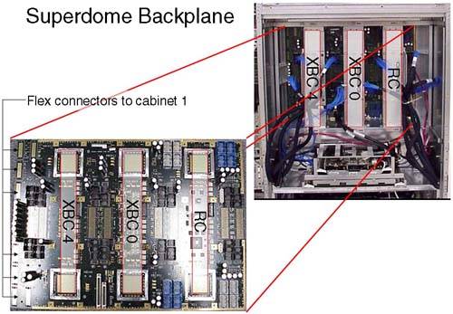
Figure 2-5. A Superdome complex. 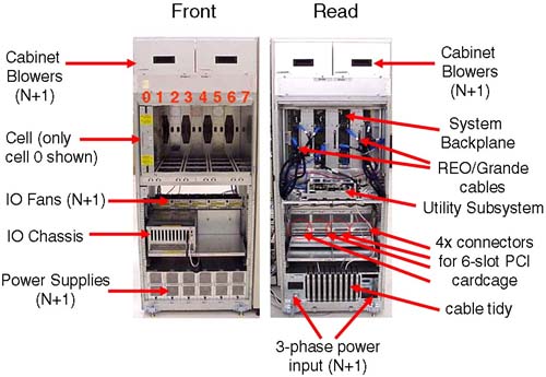
As mentioned previously, a cell board has an optional connection to an IO cardcage . This means that, if we have massive processing requirements but few IO requirements, we could configure an 8-cell partition with only one cell connected to an IO cardcage. This flexibility gives us the ability to produce a Complex Profile that meets the processing and IO requirements of all our customers utilizing the complex. Within a complex, there are a finite number of resources. Knowing what hardware components you have is crucial. Not only knowing what you have but how it is connected together is an important part of the configuration process (particularly in a Superdome). With a partitioned server, we have important choices to make regarding the configuration of nPars. Remember, we are ultimately trying to achieve two basic goals with our configuration; those two goals are High Availability and High Performance . Later, we discuss criteria to consider when constructing a partition configuration. 2.1.2 The IO cardcage The IO cardcage is an important component in a node partition configuration. Without an IO cardcage, the partition would have no IO capability and would not be able to function. It is through the IO cardcage that we gain access to our server console as well as access to all our IO devices. We must have at least one IO cardcage per node partition. At least one IO cardcage must contain a special IO card called the Core IO Card. We discuss the Core IO Card in more detail later. If an IO cardcage is connected to a cell board and the cell is powered on, we can use the PCI cards within that cardcage. If the cell is powered off, we cannot access any of the PCI cards in the IO cardcage. This further emphasizes the symbiotic relationship between the cell board and the IO cardcage. Depending on the particular machine in question, we can house two or four IO cardcages within the main cabinet of the system complex. In a single cabinet Superdome, we can accommodate four 12-slot PCI cardcages, two in the front and two in the back. If we look carefully at the IO backplane (from our Superdome example) to which the IO cardcages connect (Figure 2-3), there is the possibility to accommodate eight 6-slot PCI IO cardcages in a single cabinet. As yet, HP does not sell a 6-slot PCI IO cardcage for Superdome. Figure 2-3. Default Cell ”IO cardcage connections. 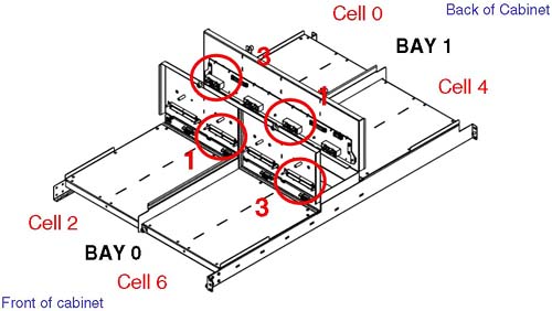
We can fit two 12-slot IO cardcages in the front of the cabinet; this is known as IO Bay 0 . We can fit a further two 12-slot IO cardcages in the rear of the cabinet; this is known as IO Bay 1 . You may have noticed in Figure 2-3 that there appear to be four connectors per IO bay (numbered from the left, 0, 1, 2 and 3); connectors number 0 and 2 are not used. Believe it or not, it is extremely important that we know which cells are connected to which IO cardcages . Taking a simple example where we wanted to configure a 2-cell partition with both cells connected to an IO cardcage , our choice of cells is important from a High Availability and a High Performance perspective. From a High Availability perspective, we would want to choose cells that were connected to one IO cardcage in IO Bay 0 and one in IO Bay 1 . The reason for this is that both IO Bays have their own IO Backplane (known as a HMIOB = Halfdome Master IO Backplane). By default, certain cells are connected to certain IO cardcages . As we can see from Figure 2-3, by default cell 0 is connected to an IO cardcage located in the rear left of the main cabinet (looking from the front of the cabinet), while cell 6 is connected to the IO cardcage front right of the cabinet. It may be that your system complex has been cabled differently from this default. There is no way of knowing which cell is connected to which IO cardcage simply by a physical inspection of the complex. This is where we need to log in to the GSP and start to use some GSP commands to analyze how the complex has been configured, from a hardware perspective. There is a numbering convention for cells, IO bays, and IO cardcages. When we start to analyze the partition configuration, we see this numbering convention come into use. This numbering convention, known as a Slot- ID , is used to identify components in the complex: components such as individual PCI cards. Table 2-1 shows a simple example: Table 2-1. Slot-ID Numbering Convention | Slot- ID = 0-1-3-1 | | 0 = Cabinet | 1 = IO Bay (rear) | 3 = IO connector (on right hand side) | 1 = Physical slot in the 12-slot PCI cardcage |
We get to the cabinet numbering in a moment. The Slot- ID allows us to identify individual PCI cards (this is very important when we perform OLA/R on individual PCI cards in Chapter 4 Advanced Peripherals Configuration). It should be noted that the cabling and cell “IO cardcage connections shown in Figure 2-3 is simply the default cabling. Should a customer specification require a different configuration, the complex would be re-cabled accordingly . Re-cabling a Superdome complex is not a trivial task and requires significant downtime of the entire complex. This should be carefully considered before asking HP to re-cable such a machine. 2.1.3 The Core IO card The only card in the IO cardcage that is unique and has a predetermined position is known as the Core IO card. This card provides console access to the partition via a USB interface from the PCI slot and the PACI (Partition Console Interface) firmware on the Core IO card itself. The only slot in a 12-slot PCI cardcage that can accommodate a Core IO card is slot 0. The PACI firmware gives access to console functionality for a partition. There is no physically separate, independent console for a partition. The Guardian Service Processor (GSP) is a centralized location for the communication to-and-from the various PACI interfaces configured within a complex. A partition must consist of at least one IO cardcage with a Core IO card in slot 0. When a Core IO card is present in an IO cardcage, the associated cell is said to be core cell capable. Core IO cards also have an external serial interface that equates to /dev/tty0p0 . This device file normally equates to the same device as /dev/console . In node partitions, /dev/console is now a virtual device with /dev/tty0p0 being the first real terminal on the first mux card. Some Core IO cards also have an external 10/100 Base-T LAN interface. This device equates to lan0 , if it exists and is nothing to do with the GSP LAN connections. Because the Core IO card can be located only in slot 0, it is a good idea to configure a partition with two IO cardcages with a Core IO card in each cardcage. While only one Core IO card can be active at any one time, having an additional Core IO card improves the overall availability of the partition. 2.1.4 System backplane If we were to take a complex configured using the default wiring we saw in Figure 2-3 and a requirement to create a 2-cell partition, it would make sense to choose cells 0 and 2, 0 and 6, 4 and 2, or 4 and 6, because all of these configurations offer us a partition with two IO cardcages, one in each IO Bay. It is not a requirement of a partition to have two IO cardcages but it does make sense from a High Availability perspective; in other words, you could configure your disk drives to be connected to interface cards in each IO cardcage. To further refine our search for suitable cell configurations, we need to discuss another piece of the hardware architecture of Node Partitionable complexes ”the system backplane and how cells communicate between each other. The XBC interface is known as the CrossBar interface and is made up of two ASIC (Application Specific Integrated Circuit) chips. The XBC interface is a high-throughput, non-blocking interface used to allow cells to communicate with each other (via the Cell Controller chip). A cell can potentially communicate with any other cell in the complex ( assuming they exist in the same nPar). For performance reasons, it is best to keep inter-cell communication as local as possible, i.e., on the same XBC interface. If this cannot be achieved, it is best to keep inter-cell communication in the same cabinet. Only when we have to, do we cross the flex-cable connectors to communicate with cells in the next cabinet. [The Routing Chips ( RC ) are currently not used. They may come into use at some time in the future.] An XBC interface connects four cells together with minimal latency; XBC0 connects cells 0, 1, 2, and 3 together, and XBC4 connects cells 4, 5, 6, and 7 together. This grouping of cells on an XBC is known as an XBC quad . If we are configuring small (2-cell) partitions, it is best to use even or odd numbered cells (this is a function of the way the XBC interface operates). The memory latencies involved when communicating between XBC interfaces is approximately 10-20 percent, with an additional 10-20 percent increase in latency when we consider communication between XBCs in different cabinets . We return to these factors when we consider which cells to choose when building a partition. We have only one system backplane in a complex. (In a dual-cabinet solution, we have two separate physical backplane boards cabled together. Even though they are two physically separate entities, they operate as one functional unit.) In some documentation, you will see XBC4 referred to a HBPB0 (Halfdome BackPlane Board 0), XBC0 as HBPB 1, and the RC interface referred to as HBPB2. Some people assume that these are independent " backplanes ." This is a false assumption. All of the XBC and RC interfaces operate within the context of a single physical system backplane. If a single component on the system backplane fails, the entire complex fails . As such the system backplane is seen as one of only three Single Points Of Failure in a complex. 2.1.5 How cells and IO cardcages fit into a complex We have mentioned the basic building blocks of an nPar: Before going any further, we look at how these components relate to each other in our Superdome example. It is sometimes a good idea to draw a schematic diagram of the major components in your complex. Later we establish which cells are connected to which IO cardcages. At that time, we could update our diagram, which could subsequently be used as part of our Disaster Recovery Planning: This is a single cabinet Superdome, i.e., a 16-way or 32-way configuration. A dual-cabinet Superdome is available where two single cabinets are located side by side and then cabled together. To some people, the dual-cabinet configuration looks like two single cabinets set next to each other. In fact, a considerable amount of configuration wiring goes into making a dual-cabinet complex, including wiring the two backplanes together to allow any cell to communicate with any other cell. You can see in Figure 2-5 that we have a single-cabinet solution. I have included the numbering of the cell boards, i.e., from left to right from 0 through to 7. In a dual-cabinet solution, the cell boards in cabinet 1 would be numbered 8 “15. A single cabinet can accommodate up to eight cells but only four IO cardcages . If we were to take a single-cabinet solution, we would be able to create four partitions as we only have 4 IO cardcages. This limitation in the number of IO cardcages frequently means that a complex will include an IO expansion cabinet . An IO expansion cabinet can accommodate an additional four IO cardcages . Each cabinet in a complex is given a unique number, even the IO expansion cabinets . Figure 2-6 shows the cabinet numbering in a dual-cabinet solution with IO expansion cabinet(s). Figure 2-6. Cabinet numbering in Superdome. 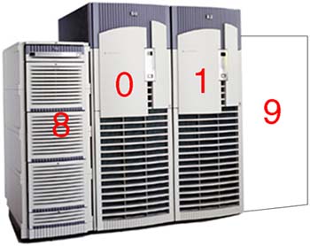
The IO expansion cabinets (numbered 8 and 9) do not have to be sited on either side of cabinets 0 and 1; they can be up to 14 feet away from the main cabinets. The reason the IO expansion cabinets are numbered from 8 is that Superdome has a built-in infrastructure that would allow for eight main cabinets (numbered 0 through to 7) containing cell- related hardware (CPU, RAM, and four 12-slot PCI cardcages) connected together using (probably) the Routing Chips that are currently left unused. Such a configuration has yet to be developed. 2.1.6 Considerations when creating a complex profile If we carefully plan our configuration, we can achieve both goals of High Availability and High Performance . Machines such as Superdome have been designed with both goals in mind. To achieve both goals may require that we make some compromises with other parts of our configuration. Understanding why these compromises are necessary is part of the configuration process. We have mentioned some High Availability and High Performance criteria when considering choice of cells and IO cardcages. We need to consider the amount of memory within a cell as well. By default, cell-based servers use interleaved memory between cells to maximize throughput; in other words, having two buses is better than one. [HP-UX 11i version 2 on the new Integrity Superdomes can configure Cell Local Memory (CLM), which is not interleaved with other cells in the partition. Future versions of HP-UX on PA-RISC and Itanium will allow the administrator to configure Cell Local Memory as and when appropriate.] To maximize the benefits of interleaving, it is best if we configure the same amount of memory in each cell and if the amount of memory is a power of 2 GBs. The way that memory chips are used by the operating system (i.e., the way a cache line is constructed ) also dictates the minimum amount of memory in each cell. The absolute minimum amount of memory is currently 2GB. This 2GB of memory is comprised of two DIMMs in the new Integrity servers (the two DIMMs are collectively known as an Echelon ) or four DIMMs in the original cell-based servers (the four DIMMs are collectively known as a Rank ). If we configure a cell with only a single Echelon/Rank and we lose that Echelon/Rank due to a hardware fault, our cell would fail to pass its Power-On Self Test (POST) and would not be able to participate in the booting of the affected partition. Consequently, it is strongly advised that we configure at least two Echelons/Ranks per cell. The same High Availability criteria can be assigned to the configuration of CPUs, i.e., configure at least two CPUs per cell and the same number of CPUs per cell. These and other High Availability and High Performance criteria can be summarized as follows : -
Configure your largest partitions first. -
Minimize XBC traffic by configuring large partitions in separate cabinets. -
Configure the same number of CPUs per cell. -
Configure the same amount of memory per cell. -
Configure a power of 2 GB of memory to aid memory interleaving. -
Configure the number of cells per partition as a power of 2. An odd number of cells will mean that a portion of memory is interleaved over a subset of cells. -
Choose cells connected to the same XBC. -
Configure at least two CPUs per cell. -
Configure at least two Echelons/Rank of memory per cell. -
Use two IO cardcages per partition. -
Install a Core IO card in each IO cardcage. -
Use even and then odd numbered cells. -
A maximum of 64 processors per partitions, e.g., 32 dual-core processors = 64 processors in total. If we marry this information back to our discussion on the default wiring of cells to IO cardcages, we start to appreciate why the default wiring has been set up in the way it has. We also start to realize the necessity of understanding how the complex has been configured in order to meet both goals of High Availability and High Performance. In the simple 2-cell example that we discussed earlier, it now becomes apparent that the optimum choice of cells would either be 0 and 2 or 4 and 6: -
Both cells are located on the same XBC minimizing latency across separate XBC interfaces. -
Both cells are already wired to a separate IO cardcages on separate IO backplanes. -
Inter-cell communication is optimized between even or odd cells. As you can imagine, the combination of cell choices for a large configuration are quite mind-blowing. In fact with a dual-cabinet configuration where we have 16 cells, the number of combinations is 2 16 = 65536. Certain combinations are not going to work well, and in fact HP has gone so far as to publish a guide whereby certain combinations of cells are the only combinations that are supported. Remember, the idea here is to produce a configuration that offers both High Availability and High Performance. The guide to choosing cells for a particular configuration is affectionately known as the nifty-54 diagram (out of the 65536 possible combinations, only 54 combinations are supported). For smaller partitionable servers, there is a scaled-down version of the nifty-54 diagram (shown in Figure 2-7) appropriate to the number of cells in the complex. Figure 2-7. Supported cell configurations (the nifty-54 diagram). 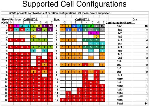
Let's apply the nifty-54 diagram to a fictitious configuration, which looks like the following (assuming that we have a 16-cell configuration): If we apply the rules we have learned and use the nifty-54 diagram , we should start with our largest partition first. -
One 6 cell partition We look down the left column of the nifty-54 diagram until we find a partition size of six cells (approximately halfway down the diagram). We then choose the cell numbers that contain the same numbers /colors. In this case, we would choose cells 0-4, 5, and 7 from either cabinet 0 or 1. Obviously, we can't keep all cells on the same XBC (the XBC can only accommodate four cells). Assuming that we have the same number/amount of CPU/RAM in each cell, we have met the High Performance criteria. In respect of High Availability, this partition is configured with two IO cardcages; by default cells 0 and 2 are connected to an IO cardcage and each IO cardcage is in a different IO bay and, hence, connected to independent IO backplanes. Partition 0: Cells from Cabinet 0 = 0, 1, 2, 3, 5, and 7. -
Two 3 cell partitions We would go through the same steps as before. This time, I would be using cells in cabinet 1 because all other cell permutations are currently being used by partition 0. The lines used in the nifty-54 diagram are in the top third of the diagram. Partition 1 : Cells from Cabinet 1 = 0, 1, and 2. Partition 2 : Cells from Cabinet 1 = 4, 5, and 6. Another thing to notice about this configuration is that both partitions are connected to two IO cardcages (cells 0 and 2 as well as cells 4 and 6) by default. This is the clever part of the nifty-54 diagram. -
One 2-cell partition Another clever aspect of the nifty-54 diagram comes to the fore at this point. We could use cells 3 and 7 from cabinet 1, but they are on a different XBC, which is not good for performance. The ideal here is cells 4 and 6 from cabinet 0; they are on the same XBC and are each by default connected to an IO cardcage. The nifty-54 diagram was devised in such a way to maximize High Performance while maintaining High-Availability in as many configurations as is possible. Partition 3 : Cells from Cabinet 0 = 4 and 6. Cells 3 and 7 in cabinet 1 are left unused. If partition 1 or partition 2 needs to be expanded in the future, we can use cell 3 for partition 1 and cell 7 for partition 2 because these cells are located on the same XBC as the original cells and, hence, maintain our High Performance design criteria. This is a good configuration. I am sure some of you have noticed that I have conveniently used all of my IO cardcages. If I wanted to utilize the two remaining cells (cells 3 and 7) in cabinet 1 as separate 1-cell partitions, I would need to add an IO Expansion cabinet to my configuration. In fact if we think about it, with a dual-cabinet configuration we can configure a maximum of eight partitions without resorting to adding an IO Expansion cabinet to our configuration (we only have eight IO cardcages within cabinets 0 and 1). If we wanted to configure eight partitions in such a configuration, we would have to abandon our High Availability criteria of using two IO cardcages per partition. This is a cost and configuration choice we all need to make. NOTE : An important part of the configuration process is to first sit down with your application suppliers, user groups, and any other customers requiring computing resources from the complex. You need to establish what their computing requirements are before constructing a complex profile. Only when we know the requirements of our customers can we size each partition. At this point, I am sure that you want to get logged into your server and start having a look around. Before you do, you need to have a few words regarding the Utility Subsystem. Referring back to Figure 2-5, a blanking plate normally hides the cells and system backplane/utility subsystem . In normal day-to-day operations, there is no reason to remove the blanking plate. Even if you were to remove it, there is no way to determine which cells are connected to which IO cardcages. It is through the Utility Subsystem that we can connect to the complex and start to analyze how it has been configured. 2.1.7 The Utility Subsystem The administrative interface (the console) to a partitionable server is via a component of the Utility Subsystem known as the Guardian Service Processor (GSP). As a CSA, you have probably used a GSP before because they are used as a hardware interface on other HP servers. The GSP on a partitionable server operates in a similar way to the GSP on other HP servers with some slight differences that we see in a few minutes. There is only one GSP in a server complex, although you may think you can find two of them in a dual-cabinet configuration. In fact, the GSP for a dual-cabinet configuration always resides in cabinet 0. The board you find in cabinet 1 is one of the two components that comprise the GSP. The GSP is made up two components piggy - backed on top of each other: a Single Board Computer (SBC) and a Single Board Computer Hub (SBCH). The SBC has a PC-based processor (an AMD K6-III usually) as well as a FLASH card, which can be used to store the Complex Profile. There is an SBCH in each cabinet in the complex because it holds an amount (6 or 12MB) of NVRAM, USB hub functionality, as well as two Ethernet and two serial port interfaces. The USB connections allow it to communicate with other SBCH boards in other cabinets. Even though there is only one GSP in a complex, it is not considered a Single Point Of Failure, as we will see later. The whole assembly can be seen in Figure 2-8. Figure 2-8. Guardian Service Processor in a Superdome. 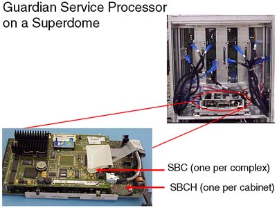
From this picture, we cannot see the two serial or two LAN connections onto the GSP. The physical connections are housed on a separate part of the Utility Subsystem. This additional board is known as the Halfdome Utility Communications (or Connector) Board (HUCB). It is difficult to see an HUCB even if you take off the blanking panel in the back of the cabinet. The GSP locates into the rear of the cabinet on a horizontal plane and plugs into two receptacles on the HUCB. The HUCB sits at 90 ° to the GSP. You can just about see the HUCB in Figure 2-9. Figure 2-9. The HUCB. 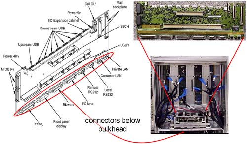
Because the HUCB is the interface board for the entire Utility Subsystem, if it fails, the entire complex fails . The HUCB is the second Single Point Of Failure in a Superdome Complex. The last component in the Utility Subsystem is known as the Unified (or United, or Universal) Glob of Utilities for Yosemite, or the UGUY (pronounced oo-guy ). As the name alludes, the UGUY performs various functions including: -
System clock circuitry . -
The cabinet power monitors , including temperature monitoring, door open monitoring, cabinet LED and switch, main power switch, main and IO cooling fans. -
Cabinet Level Utilities, including access to all backplane interfaces, distribute cabinet number and backplane locations to all cabinets, interface to GSP firmware and diagnostic testing, drive all backplane and IO LEDs. If we have a dual-cabinet configuration, we have two physical UGUY boards installed. The UGUY in cabinet 0 is the main UGUY with the UGUY in cabinet 1 being subordinate (only one UGUY can supply clock signals to the entire complex). The UGUY plugs into the HUCB in the same way as the GSP. You can see the UGUY situated below the GSP in Figure 2-10. Figure 2-10. Unified Glob of Utilities for Yosemite. 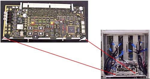
The UGUY in cabinet 0 is crucial to the operation of the complex. If this UGUY fails, the entire complex fails . The UGUY is the third and last Single Point Of Failure in a Superdome Complex. | The Three Single Points Of Failure in a Server Complex Are: The system backplane The HUCB board The UGUY board |
2.1.8 The GSP Now it's time to talk a little more about the GSP. This is our main interface to the server complex. The GSP supports four interfaces ”two serial connections and two 10/100 Base-T network connections. Initially, you may attach an HP terminal or a laptop PC in order to configure the GSP's network connections. We look at that later. Once connected, you will be presented with a login prompt. There are two users preconfigured for the GSP: One is an administrator-level user, and the other is an operator-level user. The administrator-level user has no restrictions, has a username of Admin, and a password the same as the username. Be careful, because the username and password are case-sensitive.
GSP login: Admin GSP password: (c)Copyright 2000 Hewlett-Packard Co., All Rights Reserved. Welcome to Superdome's Guardian Service Processor GSP MAIN MENU: Utility Subsystem FW Revision Level: 7.24 CO: Consoles VFP: Virtual Front Panel CM: Command Menu CL: Console Logs SL: Show chassis Logs HE: Help X: Exit Connection GSP>
Before we get into investigating the configuration of our complex, we discuss briefly the configuration of the GSP. The two 10/100 Base-T network connections have default IP addresses: The Private LAN is intended to be used by support personnel for diagnostic troubleshooting. In fact, an additional piece of hardware that you need to purchase with a Superdome server is a machine known as the Support Management Station (SMS). Originally, this would have been a small HP-UX server such as an rp2400. With the introduction of Integrity Superdomes, the SMS is now a Win2K-based server such as an HP Proliant PC. The SMS device can support up to 16 complexes. It is used exclusively by HP support staff to check and if necessary to download new firmware to a complex (remember, a Superdome complex has no internal IO devices). I know of a number of customers who use their (HP-UX based) SMS as a Software Distributor depot-server as well as a place to store HP-UX crashdumps in order to allow HP Support staff to analyze them without logging into an actual partition. The SMS does not need to be up and running to operate the complex but will have to be powered on and operational should HP Support staff require access for diagnostic troubleshooting purposes. Figure 2-11. Connections to the GSP. 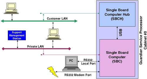
The Customer LAN is intended to be used by internal staff to connect to the GSP. Although the Private LAN and the Customer LAN may appear to have at some level different basic functionality, they offer the same level of functionality and are simply 10/100 Base-T network interfaces. The idea behind a Private LAN is to avoid having HP Support staff access a customer's corporate network. You do not need to connect or configure the Private LAN, although it is suggested that you have some form of network access from the GSP to the SMS station for diagnostic/troubleshooting purposes. The Local serial port is a 9-pin RS232 port designed to connect to any serial device with a null modem cable. The Remote serial port is a 9-pin RS232 port designed for modem access. Both RS232 ports default to 9600 baud, 8-bit, no parity, and HP- TERM compatibility. These defaults can be changed through the GSP, as we see later. The default IP addresses and the default username/password combinations should be changed as soon as possible . Should you forget or accidentally delete all administrator-level users from the GSP, you can reset the GSP to the factory default settings. To initiate such a reset, you can press the button marked on the GSP " Set GSP parameters to factory defaults " (see Figure 2-12). Figure 2-12. GSP switches 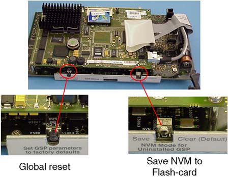
The switch marked " NVM Mode for Uninstalled GSP " allows you to write your Complex profile to the Flash-card. This can be useful if you are moving the Flash-card to another complex or you need to send the complex profile to HP for diagnostic troubleshooting. By default, the Complex Profile is held in NVRAM on the GSP and read from cell boards when necessary; in other words, the switch is set to the " Clear " position by default. 2.1.8.1 THE COMPLEX PROFILE AND THE GSP When installed, the GSP holds in NVRAM the current Complex Profile. Any changes we make to the Complex Profile, e.g., using Partition Manager commands, are sent to the GSP. The GSP will immediately send out the new Complex Profile to all cells. Every cell in the complex holds a copy of the entire Complex Profile even though only part of it will pertain to that cell. The Complex profile is made up of three parts: -
The Stable Complex Configuration Data (SCCD) contains information that pertains to the entire complex such as the name of the complex (set by the administrator), product name, model number, serial number, and so on. The SCCD also contains the cell assignment array, detailing which cells belong to which partitions. -
Dynamic Complex Configuration Data (DCCD) is maintained by the operating system. There is no way currently for any of the system boot interfaces to modify this data, so it is transparent to the user. -
Partition Configuration Data (PCD) contains partition specific information such as partition name, number, usage flags for cells, boot paths, core cell choices, and so on. Changes can be made to the Complex Profile from any partition, although only one change to the SCCD can be pending. Whenever a change affects a particular cell, that cell (and the partition it affects) will need to be rebooted in such a way as to make the new SCCD the current SCCD. Other cells that are not affected do not need to be rebooted in this way. This limitation means that adding and removing cells to a partition requires a reboot of at least that partition (assuming that no other cells currently active in another partition are involved). This special reboot is known as a reboot-for-reconfig and requires the use of a new option to the shutdown/reboot command (option “R ). Because the Complex Profile is held on every cell board, the GSP is not considered to be a Single Point Of Failure. If the GSP is removed, the complex and cells will function as normal, using the Complex Profile they have in NVRAM on the cell board. When the GSP is reinserted, it will contact all cells in order to reread the Complex Profile. The Complex Profile is surrounded by timestamp information just to ensure that the GSP obtains the correct copy (a cell board could be malfunctioning and provide invalid Complex Profile data). A drawback of not having the GSP inserted at all times is that the GSP also captures Chassis/hardware/console logs, displays complex status, and allows administrators to interface with the system console for each partition. Without the GSP inserted and working, no changes to the Complex Profile are allowed. It is suggested that the GSP is left inserted and operating at all times. There are a number of screens and commands that we should look at on the GSP. Right now, I want to get logged into the GSP and investigate how this complex has been configured. 2.1.8.2 INVESTIGATING THE CURRENT COMPLEX PROFILE Once logged into the GSP, we will perform our initial investigations from the " Command Menu ":
GSP login: Admin GSP password: (c)Copyright 2000 Hewlett-Packard Co., All Rights Reserved. Welcome to Superdome's Guardian Service Processor GSP MAIN MENU: Utility Subsystem FW Revision Level: 7.24 CO: Consoles VFP: Virtual Front Panel CM: Command Menu CL: Console Logs SL: Show chassis Logs HE: Help X: Exit Connection GSP> GSP> cm Enter HE to get a list of available commands GSP:CM>
There are quite a few commands available at the GSP Command Menu. I will use the commands that allow us to build up a picture of how this complex has been configured. By default, HP works with technical individuals in a customer organization to establish the Complex Profile that will be in place before the Superdome is shipped to the customer. While performing the following commands, it might be an idea to draw a diagram of your complex so that you can visualize how the complex has been configured. You can use this diagram as part of your Disaster Recovery Planning documentation. We can get an immediate insight as to which cells are assigned to which partitions by using the CP command:
GSP:CM> cp -------------------------------------------------------------------------------- Cabinet 0 1 2 3 4 5 6 7 --------+--------+--------+--------+--------+--------+--------+--------+-------- Slot 0123456701234567012345670123456701234567012345670123456701234567 --------+--------+--------+--------+--------+--------+--------+--------+-------- Part 0 X............................................................... Part 1 ....X........................................................... Part 2 ..X............................................................. Part 3 ......X......................................................... GSP:CM>
This tells me that I currently have four partitions configured: -
Partition 0 is made up of one cell, cell 0. -
Partition 1 is made up of one cell, cell 4. -
Partition 2 is made up of one cell, cell 2. -
Partition 3 is made up of one cell, cell 6. -
This display does not show me partition names . -
This display does not show me how many cells are currently installed in the complex. -
This display does not show me the IO cardcages to which these cells are connected. -
This display highlights the future possibility of cabinets 0 through to 7 holding cell boards. To investigate the IO cabling of the cell boards, I can use the IO command:
GSP:CM> io ------------------------------------------------------------------------------- Cabinet 0 1 2 3 4 5 6 7 --------+--------+-------+--------+--------+--------+--------+--------+-------- Slot 0123456701234567012345670123456701234567012345670123456701234567 --------+--------+-------+--------+--------+--------+--------+--------+-------- Cell X.X.X.X......................................................... IO Cab 0.0.0.0......................................................... IO Bay 1.1.0.0......................................................... IO Chas 3.1.1.3......................................................... GSP:CM>
Now I can get some idea of which cells are connected to which IO cardcages. All cells are connected to IO cardcages situated in cabinet 0: -
Cell 0 is connected to IO cardcage in Bay 1 (=rear), IO interface 3 (right side). -
Cell 2 is connected to IO cardcage in Bay 1 (=rear), IO interface 1 (left side). -
Cell 4 is connected to IO cardcage in Bay 0 (=front), IO interface 1 (left side). -
Cell 6 is connected to IO cardcage in Bay 0 (=front), IO interface 3 (right side). -
This cabling configuration is less than optimal. Can you think why? We discuss this later. We still don't know how many cells are physically installed and how much RAM and how many CPUs they possess. We need to use the PS command to do this. The PS (Power Show) command can show us the power status of individual components in the complex. Also, this will show us the hardware make-up of that component. If we perform a PS on a cell board, it will show us the status and hardware make-up of that cell board:
GSP:CM> ps This command displays detailed power and hardware configuration status. The following GSP bus devices were found: +----+-----+-----------+----------------+-----------------------------------+ Core IOs IO Bay IO Bay IO Bay IO Bay UGUY Cells 0 1 2 3 Cab. IO Chas.IO Chas.IO Chas.IO Chas. # GSP CLU PM 0 1 2 3 4 5 6 7 0 1 2 3 0 1 2 3 0 1 2 3 0 1 2 3 +----+-----+-----+-----+----------------+--------+--------+--------+--------+ 0 * * * * * * * * * * * You may display detailed power and hardware status for the following items: B - Cabinet (UGUY) C - Cell G - GSP I - Core IO Select Device:
In fact, immediately we can see which cells and IO cardcages have been discovered by the GSP (the asterisk [*] indicates that the device is installed and powered on). We now perform a PS on cells 0, 2, 4, and 6.
GSP:CM> ps This command displays detailed power and hardware configuration status. The following GSP bus devices were found: +----+-----+-----------+----------------+-----------------------------------+ Core IOs IO Bay IO Bay IO Bay IO Bay UGUY Cells 0 1 2 3 Cab. IO Chas.IO Chas.IO Chas.IO Chas. # GSP CLU PM 0 1 2 3 4 5 6 7 0 1 2 3 0 1 2 3 0 1 2 3 0 1 2 3 +----+-----+-----+-----+----------------+--------+--------+--------+--------+ 0 * * * * * * * * * * * You may display detailed power and hardware status for the following items: B - Cabinet (UGUY) C - Cell G - GSP I - Core IO Select Device: c Enter cabinet number: Enter slot number: HW status for Cell 0 in cabinet 0: NO FAILURE DETECTED Power status: on, no fault Boot is not blocked; PDH memory is shared Cell Attention LED is off RIO cable status: connected RIO cable connection physical location: cabinet 0, IO bay 1, IO chassis 3 Core cell is cabinet 0, cell 0 PDH status LEDs: ***_ CPUs 0 1 2 3 Populated * * * * Over temperature DIMMs populated: +----- A -----+ +----- B -----+ +----- C -----+ +----- D -----+ 0 1 2 3 4 5 6 7 0 1 2 3 4 5 6 7 0 1 2 3 4 5 6 7 0 1 2 3 4 5 6 7 * * * * * * * * PDC firmware rev 35.4 PDH controller firmware rev 7.8, time stamp: WED MAY 01 17:19:28 2002 GSP:CM>
Every time I run the PS command, it drops me back to the CM prompt. In the above output, I have highlighted/underscored the information of particular interest. First, I can see that the RIO cable (the blue cable connecting a cell to an IO cardcage) is connected and then I can see which IO cardcage it is connected to (confirming the output from the IO command). Then I see that this cell is Core Cell capable; in other words, its IO cardcage has a Core IO card inserted in slot 0) for partition 0 (this also helps to confirm the output from the CP command). Next I can see that this cell has all four CPUs inserted (see the Populate line). Last, I can see that I have two Echelons/Ranks of memory chips in this cell. A Rank consists of four DIMMs, e.g., 0A + 0B + 0C + 0D. Part of the High Availability design of cell-based servers is the way a cache line is stored in memory. Traditionally, a cache line will be stored in RAM on a single DIMM. If we receive a double-bit error within a cache line, HP-UX cannot continue to function and calls a halt to operations; it signals a category 1 trap; an HPMC (High Priority Machine Check). An HPMC will cause the system to crash immediately and produce a crashdump . In an attempt to help alleviate this problem, the storage of a cache line on a cell-based server is split linearly over all DIMMs in the Rank/Echelon . This means that when an HPMC is detected, HP engineers can determine which Rank/Echelon produced the HPMC. This means the HP engineer will need to change all the DIMMs that constitute that Rank/Echelon . On an original cell-based server, there are four DIMMs in a Rank (on a new Integrity server there are two DIMMs per Echelon ); therefore, I can deduce that this complex is an original Superdome and each Rank is made of 512MB DIMMs. This means that a Rank = 4 x 512MB = 2GB. This cell has two Ranks 0A+0B+0C+0D and 1A+1B+1C+1D. The total memory compliment for this cell = 2 Ranks = 4GB. I can continue to use the PS command on all remaining cells to build a picture of how this complex has been configured/cabled:
GSP:CM> ps This command displays detailed power and hardware configuration status. The following GSP bus devices were found: +----+-----+-----------+----------------+-----------------------------------+ Core IOs IO Bay IO Bay IO Bay IO Bay UGUY Cells 0 1 2 3 Cab. IO Chas.IO Chas.IO Chas.IO Chas. # GSP CLU PM 0 1 2 3 4 5 6 7 0 1 2 3 0 1 2 3 0 1 2 3 0 1 2 3 +----+-----+-----+-----+----------------+--------+--------+--------+--------+ 0 * * * * * * * * * * * You may display detailed power and hardware status for the following items: B - Cabinet (UGUY) C - Cell G - GSP I - Core IO Select Device: c Enter cabinet number: Enter slot number: 2 HW status for Cell 2 in cabinet 0: NO FAILURE DETECTED Power status: on, no fault Boot is not blocked; PDH memory is shared Cell Attention LED is off RIO cable status: connected RIO cable connection physical location: cabinet 0, IO bay 1, IO chassis 1 Core cell is cabinet 0, cell 2 PDH status LEDs: ***_ CPUs 0 1 2 3 Populated * * * * Over temperature DIMMs populated: +----- A -----+ +----- B -----+ +----- C -----+ +----- D -----+ 0 1 2 3 4 5 6 7 0 1 2 3 4 5 6 7 0 1 2 3 4 5 6 7 0 1 2 3 4 5 6 7 * * * * * * * * PDC firmware rev 35.4 PDH controller firmware rev 7.8, time stamp: WED MAY 01 17:19:28 2002 GSP:CM> GSP:CM> ps This command displays detailed power and hardware configuration status. The following GSP bus devices were found: +----+-----+-----------+----------------+-----------------------------------+ Core IOs IO Bay IO Bay IO Bay IO Bay UGUY Cells 0 1 2 3 Cab. IO Chas.IO Chas.IO Chas.IO Chas. # GSP CLU PM 0 1 2 3 4 5 6 7 0 1 2 3 0 1 2 3 0 1 2 3 0 1 2 3 +----+-----+-----+-----+----------------+--------+--------+--------+--------+ 0 * * * * * * * * * * * You may display detailed power and hardware status for the following items: B - Cabinet (UGUY) C - Cell G - GSP I - Core IO Select Device: c Enter cabinet number: Enter slot number: 4 HW status for Cell 4 in cabinet 0: NO FAILURE DETECTED Power status: on, no fault Boot is not blocked; PDH memory is shared Cell Attention LED is off RIO cable status: connected RIO cable connection physical location: cabinet 0, IO bay 0, IO chassis 1 Core cell is cabinet 0, cell 4 PDH status LEDs: **** CPUs 0 1 2 3 Populated * * * * Over temperature DIMMs populated: +----- A -----+ +----- B -----+ +----- C -----+ +----- D -----+ 0 1 2 3 4 5 6 7 0 1 2 3 4 5 6 7 0 1 2 3 4 5 6 7 0 1 2 3 4 5 6 7 * * * * * * * * PDC firmware rev 35.4 PDH controller firmware rev 7.8, time stamp: WED MAY 01 17:19:28 2002 GSP:CM> GSP:CM> ps This command displays detailed power and hardware configuration status. The following GSP bus devices were found: +----+-----+-----------+----------------+-----------------------------------+ Core IOs IO Bay IO Bay IO Bay IO Bay UGUY Cells 0 1 2 3 Cab. IO Chas.IO Chas.IO Chas.IO Chas. # GSP CLU PM 0 1 2 3 4 5 6 7 0 1 2 3 0 1 2 3 0 1 2 3 0 1 2 3 +----+-----+-----+-----+----------------+--------+--------+--------+--------+ 0 * * * * * * * * * * * You may display detailed power and hardware status for the following items: B - Cabinet (UGUY) C - Cell G - GSP I - Core IO Select Device: c Enter cabinet number: Enter slot number: 6 HW status for Cell 6 in cabinet 0: NO FAILURE DETECTED Power status: on, no fault Boot is not blocked; PDH memory is shared Cell Attention LED is off RIO cable status: connected RIO cable connection physical location: cabinet 0, IO bay 0, IO chassis 3 Core cell is cabinet 0, cell 6 PDH status LEDs: ***_ CPUs 0 1 2 3 Populated * * * * Over temperature DIMMs populated: +----- A -----+ +----- B -----+ +----- C -----+ +----- D -----+ 0 1 2 3 4 5 6 7 0 1 2 3 4 5 6 7 0 1 2 3 4 5 6 7 0 1 2 3 4 5 6 7 * * * * * * * * PDC firmware rev 35.4 PDH controller firmware rev 7.8, time stamp: WED MAY 01 17:19:28 2002 GSP:CM>
We can also confirm the existence of PACI firmware in an IO cardcage by performing a PS on an IO cardcage.
GSP:CM> ps This command displays detailed power and hardware configuration status. The following GSP bus devices were found: +----+-----+-----------+----------------+-----------------------------------+ Core IOs IO Bay IO Bay IO Bay IO Bay UGUY Cells 0 1 2 3 Cab. IO Chas.IO Chas.IO Chas.IO Chas. # GSP CLU PM 0 1 2 3 4 5 6 7 0 1 2 3 0 1 2 3 0 1 2 3 0 1 2 3 +----+-----+-----+-----+----------------+--------+--------+--------+--------+ 0 * * * * * * * * * * * You may display detailed power and hardware status for the following items: B - Cabinet (UGUY) C - Cell G - GSP I - Core IO Select Device: i Enter cabinet number: Enter IO bay number: Enter IO chassis number: 3 HW status for Core IO in cabinet 0, IO bay 0, IO chassis 3: NO FAILURE DETECTED Power status: on, no fault Boot is complete I/O Chassis Attention LED is off No session connection Host-bound console flow control is Xon GSP-bound console flow control is Xoff Host-bound session flow control is Xon GSP-bound session flow control is Xon RIO cable status: connected to cabinet 0 cell 6, no communication errors PACI firmware rev 7.4, time stamp: MON MAR 26 22:44:24 2001 GSP:CM>
I can also obtain the Core IO (CIO) firmware revision (and all other firmware revisions) using the GSP SYSREV command.
GSP:CM> sysrev Utility Subsystem FW Revision Level: 7.24 Cabinet #0 -----------------------+-----------------+ PDC PDHC Cell (slot 0) 35.4 7.8 Cell (slot 1) Cell (slot 2) 35.4 7.8 Cell (slot 3) Cell (slot 4) 35.4 7.8 Cell (slot 5) Cell (slot 6) 35.4 7.8 Cell (slot 7) GSP 7.24 CLU 7.8 PM 7.16 CIO (bay 0, chassis 1) 7.4 CIO (bay 0, chassis 3) 7.4 CIO (bay 1, chassis 1) 7.4 CIO (bay 1, chassis 3) 7.4 GSP:CM>
As we can see from all the above output, all cells have been installed with four CPUs and 4GB of RAM. Each cell is connected to an IO chassis, which we can confirm makes that cell Core Cell capable . There are currently four partitions with one cell in each. At this point, we have a good picture of how the complex has been configured; we know how many cells are installed and how many CPUs and how much RAM is installed in each. We also know how many IO cardcages we have and consequently which cells are Core Cell capable . Finally, we know how many partitions have been created. For some customers, this has been an extremely important voyage of discovery . I have often worked with highly technical support staff in customer organizations that have had no idea who was responsible for putting together the initial complex profile. For these customers, sometimes they want to start all over again because the configuration in place does not meet their requirements. A change can be as easy as modifying one or two partitions or as difficult as scrapping the entire complex profile and creating a new complex profile from scratch. When we delete all existing partitions including partition 0, the process is known as Creating the Genesis Partition . We go through the process of creating the Genesis Partition a little later. Before then, we look at other aspects of the GSP. 2.1.9 Other complex related GSP tasks I won't go over every single GSP command. There is a help function (the HE command) on the GSP as well as the system documentation if you want to review every command. What we will do is look at some of the tasks you will probably want to undertake within the first few hours/days of investigating the Complex Profile. Immediately there is the issue of the default usernames and passwords configured on the GSP. I have read various Web sites that have published details that have basically said, " If you see an HP GSP login, the username/password is Admin/Admin. " This needs to be addressed immediately. There are three categories of user we can configure on the GSP shown in Table 2-2: Table 2-2. Categories of User on the GSP | Category | Description | | Administrator | Can perform all functions on the GSP. No command is restricted. Default user = Admin/Admin. | | Operator | Can perform all functions except change the basic GSP configuration via the SO and LC commands. Default user = Oper/Oper | | Single Partition User | Can perform the same functions as an Operator, but access to partitions is limited to the partition configured by the Administrator. |
Configuring users is performed by an Administrator and is configured via the GSP Command Menu's SO (Security Options) command. There are two main options within the SO command:
GSP:CM> so 1. GSP wide parameters 2. User parameters Which do you wish to modify? ([1]/2) 1 GSP wide parameters are: Login Timeout : 1 minutes. Number of Password Faults allowed : 3 Flow Control Timeout : 5 minutes. Current Login Timeout is: 1 minutes. Do you want to modify it? (Y/[N]) n Current Number of Password Faults allowed is: 3 Do you want to modify it? (Y/[N]) n Current Flow Control Timeout is: 5 minutes. Do you want to modify it? (Y/[N]) n GSP:CM>
As you can see, the first option is to configure global Security Options features. The second option is to add/modify/delete users.
GSP:CM> so 1. GSP wide parameters 2. User parameters Which do you wish to modify? ([1]/2) 2 Current users: LOGIN USER NAME ACCESS PART. STATUS 1 Admin Administrator Admin 2 Oper Operator Operator 3 stevero Steve Robinson Admin 4 melvyn Melvyn Burnard Admin 5 peterh peter harrison Admin 6 root root Admin 7 ooh ooh Admin 1 to 7 to edit, A to add, D to delete, Q to quit :
I could select 1, which would allow me to modify an existing user. In this example, I add a new user:
GSP:CM> so 1. GSP wide parameters 2. User parameters Which do you wish to modify? ([1]/2) 2 Current users: LOGIN USER NAME ACCESS PART. STATUS 1 Admin Administrator Admin 2 Oper Operator Operator 3 stevero Steve Robinson Admin 4 melvyn Melvyn Burnard Admin 5 peterh peter harrison Admin 6 root root Admin 7 ooh ooh Admin 1 to 7 to edit, A to add, D to delete, Q to quit : a Enter Login : tester Enter Name : Charles Keenan Enter Organization : HP Response Centre Valid Access Levels: Administrator, Operator, Single Partition User Enter Access Level (A/O/[S]) : A Valid Modes: Single Use, Multiple Use Enter Mode (S/[M]) : S Valid States: Disabled, Enabled Enter State (D/[E]) : E Enable Dialback ? (Y/[N]) N Enter Password : Re-Enter Password : New User parameters are: Login : tester Name : Charles Keenan Organization : HP Response Centre Access Level : Administrator Mode : Single Use State : Enabled Default Partition : Dialback : (disabled) Changes do not take affect until the command has finished. Save changes to user number 8? (Y/[N]) y Current users: LOGIN USER NAME ACCESS PART. STATUS 1 Admin Administrator Admin 2 Oper Operator Operator 3 stevero Steve Robinson Admin 4 melvyn Melvyn Burnard Admin 5 peterh peter harrison Admin 6 root root Admin 7 ooh ooh Admin 8 tester Charles Keenan Admin Single Use 1 to 8 to edit, A to add, D to delete, Q to quit : q GSP:CM>
This list provides a brief description of some of the features of a user account: -
Login : A unique username -
Name : A descriptive name for the user -
Organization : Further information to identify the user -
Valid Access Level : The type of user to configure -
Valid Mode : Whether more than one user can login using that username -
Valid States : Whether the account is enabled (login allowed) or disabled (login disallowed ) -
Enable Dialback : If it is envisaged, this username will be used by users access the Remote (modem) RS232 port then when logged in, the GSP will drop the line and dialback on the telephone number used to dial in. -
Password : A sensible password, please -
Re-enter password : Just to be sure I will now delete that user.
GSP:CM> so 1. GSP wide parameters 2. User parameters Which do you wish to modify? ([1]/2) 2 Current users: LOGIN USER NAME ACCESS PART. STATUS 1 Admin Administrator Admin 2 Oper Operator Operator 3 stevero Steve Robinson Admin 4 melvyn Melvyn Burnard Admin 5 peterh peter harrison Admin 6 root root Admin 7 ooh ooh Admin 8 tester Charles Keenan Admin 1 to 8 to edit, A to add, D to delete, Q to quit : d Delete which user? (1 to 8) : 8 Current User parameters are: Login : tester Name : Charles Keenan Organization : HP Response Centre Access Level : Administrator Mode : Single Use State : Enabled Default Partition : Dialback : (disabled) Delete user number 8? (Y/[N]) y Current users: LOGIN USER NAME ACCESS PART. STATUS 1 Admin Administrator Admin 2 Oper Operator Operator 3 stevero Steve Robinson Admin 4 melvyn Melvyn Burnard Admin 5 peterh peter harrison Admin 6 root root Admin 7 ooh ooh Admin 1 to 7 to edit, A to add, D to delete, Q to quit : q GSP:CM>
Please remember that an Administrator can delete every user configured on the GSP, even the preconfigured users Admin and Oper . You have been warned ! Another task you will probably want to undertake fairly quickly is to change the default LAN IP addresses. This is accomplished by the LC (Lan Config) command and can be viewed with the LS (Lan Show) command:
GSP:CM> ls Current configuration of GSP customer LAN interface MAC address : 00:10:83:fd:57:74 IP address : 15.145.32.229 0x0f9120e5 Name : uksdgsp Subnet mask : 255.255.248.0 0xfffff800 Gateway : 15.145.32.1 0x0f912001 Status : UP and RUNNING Current configuration of GSP private LAN interface MAC address : 00:a0:f0:00:c3:ec IP address : 192.168.2.10 0xc0a8020a Name : priv-00 Subnet mask : 255.255.255.0 0xffffff00 Gateway : 192.168.2.10 0xc0a8020a Status : UP and RUNNING GSP:CM> GSP:CM> lc This command modifies the LAN parameters. Current configuration of GSP customer LAN interface MAC address : 00:10:83:fd:57:74 IP address : 15.145.32.229 0x0f9120e5 Name : uksdgsp Subnet mask : 255.255.248.0 0xfffff800 Gateway : 15.145.32.1 0x0f912001 Status : UP and RUNNING Do you want to modify the configuration for the customer LAN? (Y/[N]) y Current IP Address is: 15.145.32.229 Do you want to modify it? (Y/[N]) n Current GSP Network Name is: uksdgsp Do you want to modify it? (Y/[N]) n Current Subnet Mask is: 255.255.248.0 Do you want to modify it? (Y/[N]) n Current Gateway is: 15.145.32.1 Do you want to modify it? (Y/[N]) (Default will be IP address.) n Current configuration of GSP private LAN interface MAC address : 00:a0:f0:00:c3:ec IP address : 192.168.2.10 0xc0a8020a Name : priv-00 Subnet mask : 255.255.255.0 0xffffff00 Gateway : 192.168.2.10 0xc0a8020a Status : UP and RUNNING Do you want to modify the configuration for the private LAN? (Y/[N]) y Current IP Address is: 192.168.2.10 Do you want to modify it? (Y/[N]) n Current GSP Network Name is: priv-00 Do you want to modify it? (Y/[N]) n Current Subnet Mask is: 255.255.255.0 Do you want to modify it? (Y/[N]) n Current Gateway is: 192.168.2.10 Do you want to modify it? (Y/[N]) (Default will be IP address.) n GSP:CM>
There are many other GSP commands, but we don't need to look at them at this moment. The next aspects of the GSP we need to concern ourselves with are the other screens we may want to utilize when configuring a complex. Essentially, I think we need a minimum of three screens and one optional screen active whenever we manage a complex: -
A Command Menu screen, for entering GSP commands. -
A Virtual Front Panels screen, to see the diagnostic state of cells in a partition while it is booting. -
A Console screen, giving us access to the system console for individual partitions. -
A Chassis/Console Log screen (optional), for viewing hardware logs if we think there may be a hardware problem (optional). I navigate to this screen from the Command Menu screen, if necessary. These screens are accessible from the main GSP prompt. Utilizing the LAN connection and some terminal emulation software means that we can have all three screens on the go while we configure/manage the complex. Screens such as the Command Menu screen are what I call passive screens; they just sit there until we do something, which we saw earlier. To return to the Main Menu in a GSP passive screen, we use the MA command. Screens such as the Virtual Front Panel ( VFP ) I refer to as active screens because the content is being updated constantly. This is not going to work very well, but here is a screenshot from my Virtual Front Panel screen:
GSP> vfp Partition VFPs available: # Name --- ---- 0) uksd1 1) uksd2 2) uksd3 3) uksd4 S) System (all chassis codes) Q) Quit GSP:VFP> s E indicates error since last boot # Partition state Activity - --------------- -------- 0 HPUX heartbeat: 1 HPUX heartbeat: * 2 HPUX heartbeat: * 3 HPUX heartbeat: GSP:VFP (^B to Quit) > ^b GSP MAIN MENU: CO: Consoles VFP: Virtual Front Panel CM: Command Menu CL: Console Logs SL: Show chassis Logs HE: Help X: Exit Connection GSP>
As you can see, I could have viewed the Virtual Front Panel for any of my partitions, but I chose to view a general VFP for the entire complex. Being an active screen, to return to the GSP prompt, we simply press ctrl-b . The idea behind the VFP is to provide a simple diagnostic interface to relay the state of cells and partitions. On traditional servers, there was either an LCD/LED display on front of the server or hex numbers displayed on the bottom of the system console. Because we don't have a single server of a single system console, the VFP replaces (and exceeds, it must be said) the old diagnostic HEX codes displayed by a traditional server. My VFP output above tells me that my four partitions have HP-UX up and running. The Console window allows us to view and gain access to the system console for a particular partition (or just a single partition for a Single Partition User). This may be necessary to interact with the HP-UX boot process or to gain access to the system console for other administrative tasks. Because we are not changing any part of the GSP configuration, an Operator user can access the console for any partition and interact with the HP-UX boot sequence, as if they were seated in front of the physical console for a traditional server. I mention this because some customers I have worked with have assumed that being only an Operator means that you don't get to interact with the HP-UX boot sequence. My response to this is simple. With a traditional server, you need to secure the boot sequence if you think that particular interface is insecure , i.e., single-user mode authentication. Node Partitions behave in exactly the same way and need the same level of consideration.
GSP> co Partitions available: # Name --- ---- 0) uksd1 1) uksd2 2) uksd3 3) uksd4 Q) Quit Please select partition number: 3 Connecting to Console: uksd4 (Use ^B to return to main menu.) [A few lines of context from the console log:] - - - - - - - - - - - - - - - - - - - - - - - - - - - - - - - .sw home opt stand usr root@uksd4 #exit logout root [higgsd@uksd4] exit logout uksd4 [HP Release B.11.11] (see /etc/issue) Console Login: - - - - - - - - - - - - - - - - - - - - - - - - - - - - - - - uksd4 [HP Release B.11.11] (see /etc/issue) Console Login:
The Console interface is considered an active screen. Consequently, to return to the GSP, we simply press ctlr-b as we did in the VFP screen. Remember that if you leave a Console session logged in, it will remain logged in; it behaves like a physical console on a traditional server. Think about setting a logout timer in your shell (the shell LOGOUT environment variable). I mentioned the Chassis Logs screen as being an optional screen when first setting up and managing a complex. Chassis Logs (viewed with the SL [Show Logs] command) are hardware diagnostic messages captured by the Utility Subsystem and stored on the GSP. Chassis Logs are time stamped. If you see recent Error Logs, it is worthwhile to contact your local HP Response Center and place a Hardware Call in order for an engineer to investigate the problem further. Unread Error Logs will cause the Fault LED on the Front and Rear of the cabinet to flash an orange color .
GSP> sl Chassis Logs available: (A)ctivity Log (E)rror Log (L)ive Chassis Logs (C)lear All Chassis Logs (Q)uit GSP:VW> e To Select Entry: (<CR> or <space>) View next or previous block (+) View next block (forwards in time) (-) View previous block (backwards in time) (D)ump entire log for capture and analysis (F)irst entry (L)ast entry (J)ump to entry number (V)iew Mode Select (H)elp to repeat this menu ^B to exit GSP:VWR (<CR>,<sp>,+,-,D,F,L,J,V,H,^B) > <cr> # Location Alert Keyword Timestamp 2511 PM 0 *2 0x5c20082363ff200f 0x000067091d141428 BLOWER_SPEED_CHG 2510 PM 0 *4 0x5c2008476100400f 0x000067091d141428 DOOR_OPENED 2509 PM 0 *2 0x5c20082363ff200f 0x000067091d141426 BLOWER_SPEED_CHG 2508 PM 0 *4 0x5c2008476100400f 0x000067091d141426 DOOR_OPENED 2507 PM 0 *2 0x5c20082363ff200f 0x000067091d141301 BLOWER_SPEED_CHG 2506 PM 0 *4 0x5c2008476100400f 0x000067091d141301 DOOR_OPENED 2505 PDC 0,2,0 *2 0x180084207100284c 0x0000000000000001 MEM_CMAP_MIN_ZI_DEFAUD 2505 PDC 0,2,0 *2 0x58008c0000002840 0x000067091d11172c 10/29/2003 17:23:44 2504 PDC 0,2,0 *2 0x180085207100284c 0x0000000000000001 MEM_CMAP_MIN_ZI_DEFAUD 2504 PDC 0,2,0 *2 0x58008d0000002840 0x000067091d10372f 10/29/2003 16:55:47 2503 PDC 0,2,0 *2 0x180086207100284c 0x0000000000000001 MEM_CMAP_MIN_ZI_DEFAUD 2503 PDC 0,2,0 *2 0x58008e0000002840 0x000067091d101a13 10/29/2003 16:26:19 2502 PDC 0,2,0 *2 0x180087207100284c 0x0000000000000001 MEM_CMAP_MIN_ZI_DEFAUD 2502 PDC 0,2,0 *2 0x58008f0000002840 0x000067091d0f0d09 10/29/2003 15:13:09 2501 PDC 0,2,0 *2 0x180081207100284c 0x0000000000000001 MEM_CMAP_MIN_ZI_DEFAUD 2501 PDC 0,2,0 *2 0x5800890000002840 0x000067091d0e0b34 10/29/2003 14:11:52 2500 HPUX 0,2,2 *3 0xf8e0a3301100effd 0x000000000000effd 2500 HPUX 0,2,2 *3 0x58e0ab000000eff0 0x000067091d0e0712 10/29/2003 14:07:18 2499 HPUX 0,2,2 *3 0xf8e0a2301100e000 0x000000000000e000 2499 HPUX 0,2,2 *3 0x58e0aa000000e000 0x000067091d0e0623 10/29/2003 14:06:35 2498 HPUX 0,2,2 *12 0xa0e0a1c01100b000 0x00000000000005e9 OS Panic 2498 HPUX 0,2,2 *12 0x58e0a9000000b000 0x000067091d0e061a 10/29/2003 14:06:26 GSP:VWR (<CR>,<sp>,+,-,D,F,L,J,V,H,^B) > ^b GSP MAIN MENU: CO: Consoles VFP: Virtual Front Panel CM: Command Menu CL: Console Logs SL: Show chassis Logs HE: Help X: Exit Connection GSP>
One final issue regarding the various screens accessible via the GSP is that if you and a colleague are interacting with the same screen, e.g., a PS command within a Command Menu screen, you will see what each other is doing. You can see who else is logged in to the GSP with the WHO command:
GSP:CM> who User Login Port Name IP Address Admin LAN 192.168. 2.101 Admin LAN 15.196. 6. 52 GSP:CM>
Another way of communicating with other GSP users is to broadcast a message to all users using the TE command. If I am logged in to an RS232 port, I can disable all LAN access using the DL command ( EL to re-enable LAN access) and the DI (Disconnect Remote of LAN console) command. If I want to disable access via the Remote (modem) port, I can use the DR command ( ER to enable Remote access). We will return to the GSP later when we create new partitions. Now, I want to return to the topic of the IO cardcage. In particular, I want to discuss how the slot numbering in the IO cardcage is translated into an HP-UX hardware path . This might not seem like an exciting topic to discuss, but it is absolutely crucial if we are going to understand HP-UX hardware paths and their relationship to Slot-IDs . When it comes time to install HP-UX, we need to know the HP-UX hardware path to our LAN cards if we are going to boot from an Ignite-UX server. The process of converting a Slot-ID to an HP-UX hardware path is not a straightforward as you would at first think. 2.1.10 IO Cardcage slot numbering The IO cardcage on a Superdome is a 12-slot PCI cardcage. Other cell-based servers have a 6-slot PCI cardcage. The cardcage hosts both dual-speed and quad speed PCI cards. A traditional Superdome complex has eight dual-speed slots (64-bit, 33 MHz) and four quad-speed slots (64-bit, 66MHz). The new Integrity servers use PCI-X interfaces. This means that on an Integrity Superdome, we have eight quad-speed cards (64-bit PCI-X, 66MHz) and four eight-speed slots (64-bit PCI-X, 133MHz). The new Integrity servers use a new chipset for the IO subsystem (the REO chip is now known as a Grande chip, and the IO interface chips are now known as Mercury chips instead of Elroys ). To make my diagrams easier to follow, I will refer to the original Superdome infrastructure where we have dual- and quad- speed slots as well as REO and Elroy chips. To translate Figures 2-13 and 2-14 to be appropriate for an Integrity server, you would replace Elroy with Mercury , 2x with 4x, and 4x with 8x . Otherwise , the ideas are the same. Figure 2-13. IO cardage connections. 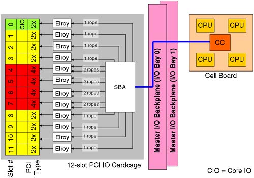
Figure 2-14. IO cardcage slot number to LBA addressing. 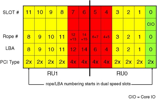
What is not evident is the effect a quad-speed card has on the HP-UX hardware path. This is where we introduce a little bit of HP-hardware-techno-speak; it's there to explain why the HP-UX hardware path looks a bit weird in comparison to the physical slot number in the IO cardcage. Let's look at a block diagram of what we are going to explain: A cell that is connected to an IO cardcage communicates with the IO cardcage via a link from the Cell Controller to a single System Bus Adapter (SBA) chip located on the power board of the IO cardcage and routed via the Master IO backplane. The SBA supports up to 16 ropes (a rope being an HP name for an interface to a PCI card). The circuitry that communicates with the actual PCI card is known as an Elroy chip ( newer Integrity servers use a Mercury chip to talk to a PCI-X interface). To communicate with a dual-speed interface, the Elroy uses a single rope . To communicate with a quad-speed interface, the Elroy requires two ropes . It is the rope number that is used as the Local Bus Address (LBA) in the HP-UX hardware path. At first this seems overly complicated, unnecessary, and rather confusing. We discuss it because we need to be able to locate a physical PCI card either via its Slot-ID or its HP-UX hardware path. We also need to be able to relate a Slot-ID to the appropriate HP-UX hardware path. It will become clear, honest! The LBA on an Integrity server are derived in the same way. One of the reasons behind the numbering is that an SBA is made up of two Rope Units (RU0 and RU1). In the future, there is the potential to supply a 6-slot PCI cardcage for Superdome (we saw that four connectors are already there on the Master IO Backplane). A 6-slot IO cardcage only needs one Rope Unit, and we always start the rope/LBA numbering in the dual-speed slots. The way I try to visualize Figure 2-14 is that they have taken two 6-slot PCI cardcages and connected them by sticking the quad speeds slots back to back . We can now discuss how this has an impact on the hardware addressing we see in our partitions. 2.1.10.1 HP-UX HARDWARE ADDRESSING ON A NODE PARTITION Some of you may be wondering why we are spending so much time on hardware addressing. Is this really a job for commands such as ioscan ? Yes, it is. However, once we have created a partition, we will need to boot the partition from install media to install the operating system. On a traditional server, we have a boot interface such as the Boot Console Handler ( BCH ), which is known as the Extensible Firmware Interface ( EFI ) on an Integrity server. At this interface, we have commands to search for potential boot devices. We can even search on the network for potential install servers:
Main Menu: Enter command or menu > sea lan install Searching for potential boot device(s) - on Path 0/0/0/0 This may take several minutes. To discontinue search, press any key (termination may not be immediate). Path# Device Path (dec) Device Path (mnem) Device Type ----- ----------------- ------------------ ----------- P0 0/0/0/0 lan.192.168.0.35 LAN Module Main Menu: Enter command or menu >
On a Node Partition, we do not have a logical device known as lan at the boot interface. That's because there are two many permutations of physical hardware paths that would all need to be translated to the logical lan device. Consequently, we have to know the specific hardware address for our LAN cards and supply that address to the BCH search command. This is why we are spending so long discussing hardware paths and how to work them out by analyzing the content of your PCI cardcage. Here's a quick list of how to work out a hardware path shown in Figure 2-15. Figure 2-15. Hardware path description. 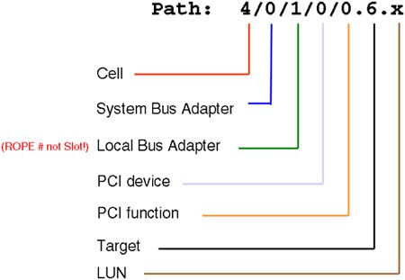
Here is a breakdown of the individual components of the Hardware Path: -
Cell : This is the physical cell number where the device is located or connected. -
SBA : For IO devices, e.g., interface cards, disks, and so on, the SBA is always 0, because a cell can only be physically connected to a single IO cardcage. If the device in question is a CPU, individual CPUs are numbered 10, 11, 12, and 13 on a traditional Superdome. On an Integrity Superdome, CPUs are numbered 120, 121, 122, and 123. -
LBA : This is the rope/LBA number we saw in Figure 2-14. -
PCI device : On a traditional Superdome, this number is always 0 (using Elroy chips). On an Integrity Superdome with PCI-X cards, this number is always 1 (using Mercury chips). It's a neat trick to establish which IO architecture we are using. -
PCI Function : On a single function card, this is always 0. On a card such as dual-port Fire Channel card, each port has its own PCI Function number, 0 and 1. -
Target : We are now into the device-specific part of the hardware path. This can be information such as SCSI target ID, Fibre Channel N-Port ID, and so on. -
LUN : This is more device-specific information such as the SCSI LUN number. A command that can help translate Slot-IDs into the corresponding HP-UX hardware paths is the rad -q command ( olrad -q on an Integrity server):
root@uksd4 # rad -q Driver(s) Slot Path Bus Speed Power Occupied Suspended Capable 0-0-3-0 6/0/0 0 33 On Yes No No 0-0-3-1 6/0/1/0 8 33 On Yes No Yes 0-0-3-2 6/0/2/0 16 33 On Yes No Yes 0-0-3-3 6/0/3/0 24 33 On Yes No Yes 0-0-3-4 6/0/4/0 32 33 On Yes No Yes 0-0-3-5 6/0/6/0 48 33 On Yes No Yes 0-0-3-6 6/0/14/0 112 66 On Yes No Yes 0-0-3-7 6/0/12/0 96 33 On No N/A N/A 0-0-3-8 6/0/11/0 88 33 On Yes No Yes 0-0-3-9 6/0/10/0 80 33 On Yes No Yes 0-0-3-10 6/0/9/0 72 33 On Yes No Yes 0-0-3-11 6/0/8/0 64 33 On Yes No Yes root@uksd4 #
Here we can see that cell 6 (the first component of the hardware path) is connected to IO cardcage in cabinet 0, IO Bay, IO connector 3 (0-0-3 in the Slot-ID). We can still use the ioscan command to find which types of cards are installed in these slots.
root@uksd4 # ioscan -fnkC processor Class I H/W Path Driver S/W State H/W Type Description =================================================================== processor 0 6/10 processor CLAIMED PROCESSOR Processor processor 1 6/11 processor CLAIMED PROCESSOR Processor processor 2 6/12 processor CLAIMED PROCESSOR Processor processor 3 6/13 processor CLAIMED PROCESSOR Processor root@uksd4 # root@uksd4 # ioscan -fnkH 6/0/8/0 Class I H/W Path Driver S/W State H/W Type Description ====================================================================== ext_bus 7 6/0/8/0/0 c720 CLAIMED INTERFACE SCSI C87x Ultra Wide Differential target 18 6/0/8/0/0.7 tgt CLAIMED DEVICE ctl 7 6/0/8/0/0.7.0 sctl CLAIMED DEVICE Initiator /dev/rscsi/c7t7d0 ext_bus 8 6/0/8/0/1 c720 CLAIMED INTERFACE SCSI C87x Ultra Wide Differential target 19 6/0/8/0/1.7 tgt CLAIMED DEVICE ctl 8 6/0/8/0/1.7.0 sctl CLAIMED DEVICE Initiator /dev/rscsi/c8t7d0 root@uksd4 #
In the examples above, we can confirm that there are four CPUs within cell 6. We can also say that in slot 11 (LBA=8) we have a dual-port Ultra-Wide SCSI card (PCI Function 0 and 1). We should perform some analysis of our configuration in order to establish the hardware paths of our LAN cards. Armed with this information, we can interact with the boot interface and perform a search on our LAN devices for potential install servers.
root@uksd4 # lanscan Hardware Station Crd Hdw Net-Interface NM MAC HP-DLPI DLPI Path Address In# State NamePPA ID Type Support Mjr# 6/0/0/1/0 0x001083FD9D57 0 UP lan0 snap0 1 ETHER Yes 119 6/0/2/0/0 0x00306E0C74FC 1 UP lan1 snap1 2 ETHER Yes 119 6/0/9/0/0 0x00306E0CA400 2 UP lan2 snap2 3 ETHER Yes 119 6/0/10/0/0 0x0060B0582B95 3 UP lan3 4 FDDI Yes 119 6/0/14/0/0 0x00306E0F09C8 4 UP lan4 snap4 5 ETHER Yes 119 root@uksd4 # root@uksd4 # ioscan -fnkC lan Class I H/W Path Driver S/W State H/W Type Description ==================================================================== lan 0 6/0/0/1/0 btlan CLAIMED INTERFACE HP PCI 10/100Base-TX Core /dev/diag/lan0 /dev/ether0 /dev/lan0 lan 1 6/0/2/0/0 btlan CLAIMED INTERFACE HP A5230A/B5509BA PCI 10  /100Base-TX Addon /dev/diag/lan1 /dev/ether1 /dev/lan1 lan 2 6/0/9/0/0 btlan CLAIMED INTERFACE HP A5230A/B5509BA PCI 10 /100Base-TX Addon /dev/diag/lan2 /dev/ether2 /dev/lan2 lan 3 6/0/10/0/0 fddi4 CLAIMED INTERFACE PCI FDDI Adapter HP A3739B /dev/lan3 lan 4 6/0/14/0/0 gelan CLAIMED INTERFACE HP A4929A PCI 1000Base-T Adapter root@uksd4 # /100Base-TX Addon /dev/diag/lan1 /dev/ether1 /dev/lan1 lan 2 6/0/9/0/0 btlan CLAIMED INTERFACE HP A5230A/B5509BA PCI 10 /100Base-TX Addon /dev/diag/lan2 /dev/ether2 /dev/lan2 lan 3 6/0/10/0/0 fddi4 CLAIMED INTERFACE PCI FDDI Adapter HP A3739B /dev/lan3 lan 4 6/0/14/0/0 gelan CLAIMED INTERFACE HP A4929A PCI 1000Base-T Adapter root@uksd4 #
Obviously, to use commands like ioscan and rad , we need to have HP-UX already installed! It should be noted that just about every complex would come with preconfigured partitions and an operating system preinstalled within those partitions. IMPORTANT Spend some time reviewing the relationship between a Slot-ID and an HP-UX hardware path; it's not immediately obvious but is necessary for tasks such as booting from a particular device, installing the operating system, and replacing components using OLA/R techniques. Review the output of commands such as ioscan, and rad “q. |
It should be noted that the new Integrity servers can display hardware paths using the Extensible Firmware Interface (EFI) numbering convention. See the ioscan “e command for more details. At this point, we are ready to move on and look at managing/creating partitions. I have made the decision to create a new complex profile from scratch; in other words, I am going to create the Genesis Partition. Before doing so, I must ensure that I understand the High Availability and High Performance design criteria for creating partitions. I may also want to document the current partition configuration as seen from the HP-UX perspective. With the parstatus command below, I can see a one-liner for each configured partition in the complex:
root@uksd4 # parstatus -P [Partition] Par # of # of I/O Num Status Cells Chassis Core cell Partition Name (first 30 chars) === ============ ===== ======== ========== =============================== 0 active 1 1 cab0,cell0 uksd1 1 active 1 1 cab0,cell4 uksd2 2 active 1 1 cab0,cell2 uksd3 3 active 1 1 cab0,cell6 uksd4 root@uksd4 #
I can gain useful, detailed information pertaining to each partition using the parstatus command but targeting a particular partition:
root@uksd4 # parstatus -Vp 0 [Partition] Partition Number : 0 Partition Name : uksd1 Status : active IP address : 0.0.0.0 Primary Boot Path : 0/0/1/0/0.0.0 Alternate Boot Path : 0/0/1/0/0.5.0 HA Alternate Boot Path : 0/0/1/0/0.6.0 PDC Revision : 35.4 IODCH Version : 5C70 CPU Speed : 552 MHz Core Cell : cab0,cell0 [Cell] CPU Memory Use OK/ (GB) Core On Hardware Actual Deconf/ OK/ Cell Next Par Location Usage Max Deconf Connected To Capable Boot Num ========= ============ ======= ========= =================== ======= ==== === cab0,cell0 active core 4/0/4 4.0/ 0.0 cab0,bay1,chassis3 yes yes 0 [Chassis] Core Connected Par Hardware Location Usage IO To Num =================== ============ ==== ========== === cab0,bay1,chassis3 active yes cab0,cell0 0 root@uksd4 #
I would normally list and store the detailed configuration for each partition before creating the Genesis Partition in case I wanted to reinstate the old configuration at some later data. Notice that this is the first time we have been able to establish the speed of the processors within a cell; the PS command does not show you this. Sometimes, there is a sticker/badge on the cell board itself, but this can't always be relied on (you may have had several upgrades since then). In order to create the Genesis Partition, I must shut down all active partitions in such a way that they will be halted and ready to accept a new complex profile. This is similar to the reboot-for-reconfig concept we mentioned earlier when we discussed making changes to the Complex Profile. The only difference here is that we are performing a halt-for-reconfig; in other words, each partition will be ready to accept a new Complex Profile but will not restart automatically. This requires two new options to the shutdown command: -
-R : Shuts down the system to a ready-to-reconfig state and reboots automatically. This option is available only on systems that support hardware partitions. -
-H : Shuts down the system to a ready-to-reconfig state and does not reboot. This option can be used only in combination with the -R option. This option is available only on systems that support hardware partitions. In essence, when we create the Genesis Partition, all cells need to be in an Inactive state; otherwise, the process will fail. I am now going to run the shutdown “RH now command on all partitions. |